2011 MERCEDES-BENZ CLS flat tire
[x] Cancel search: flat tirePage 202 of 308
cornering, hydroplaning, or peak traction
characteristics.
The traction grades, from highest to lowest,
are AA, A, B, and C. Those grades represent
the tire’s ability to stop on wet pavement as
measured under controlled conditions on
specified
government test surfaces of asphalt
and concrete. A tire marked C may have poor
traction performance. G
Warning!
If ice has formed on the road, tire traction will
be
substantially reduced. Under such weather
conditions, drive, steer and brake with
extreme caution.
The safe speed on a wet, snow covered or icy
road is always lower than on a dry road.
You should pay particular attention to the
condition of the road whenever the outside
temperature is close to the freezing point.
Mercedes-Benz recommends winter tires
(Y page 208) with a minimum tread depth of
approximately 1
/ 6 in (4 mm) on all four wheels
for the winter season to ensure normal
balanced handling characteristics. On
packed snow, they can reduce your stopping
distance compared to summer tires.
Stopping distance, however, is still
considerably greater than when the road is
not covered with snow or ice. Exercise
appropriate caution.
! Avoid spinning of a drive wheel. This may
cause serious damage to the drivetrain
which is not covered by the Mercedes-Benz
Limited Warranty.
Temperature G
Warning!
The temperature grade for this tire is
established for a tire that is properly inflated
and not overloaded. Excessive speed,
underinflation, or excessive loading, either
separately or in combination, can cause excessive heat build-up and possible tire
failure.
The temperature grades are A (the highest),
B,
and C, representing the tire’s resistance to
the generation of heat and its ability to
dissipate heat when tested under controlled
conditions on a specified indoor laboratory
test wheel. Sustained high temperature can
cause the material of the tire to degenerate
and reduce tire life, and excessive
temperature can lead to sudden tire failure.
The grade C corresponds to a level of
performance which all passenger car tires
must meet under the Federal Motor Vehicle
Safety Standard No. 109. Grades B and A
represent higher levels of performance on the
laboratory test wheel than the minimum
required by law. Rotating tires
G
Warning!
Rotate front and rear wheels only if the tires
are of the same dimension.
If your vehicle is equipped with mixed-size
tires
(different tire dimensions front vs. rear),
tire rotation is not possible. G
Warning!
Have the tightening torque checked after
changing a wheel. Wheels could become
loose if not tightened with a torque of
96 lb-ft (130 Nm).
Only
use genuine Mercedes-Benz wheel bolts
specified for your vehicle’s rims.
Tire rotation can be performed on vehicles
with tires of the same dimension all around.
If your vehicle is equipped with tires of the
same dimension all around, tires can be
rotated, observing a front-to-rear rotation
pattern that will maintain the intended
rotation (spinning) direction of the tire
(Y page 197).
In some cases, such as when your vehicle is
equipped with mixed-size tires (different tire 200
Tires and wheels
Operation
219_AKB; 4; 54, en-US
d2ureepe,
Version: 2.11.8.1 2009-05-11T16:21:02+02:00 - Seite 200
Page 203 of 308
dimension front vs. rear), tire rotation is not
possible.
If applicable to your vehicle’s tire
configuration, tires can be rotated according
to the tire manufacturer’s recommended
intervals in the tire manufacturer’s warranty
pamphlet located in your vehicle literature
portfolio. If none is available, tires should be
rotated every 3 000 to 6
000 miles (5 000 to
10 000 km), or sooner if necessary, according
to the degree of tire wear. The same rotation
(spinning) direction must be maintained.
Rotate tires before the characteristic tire
wear pattern becomes visible (shoulder wear
on front tires and tread center wear on rear
tires).
Thoroughly clean the mounting face of wheels
and brake disks, i.e. the inner side of the
wheels/tires, during each rotation. Check for
and ensure proper tire inflation pressure.
For information on wheel change, see “Flat
tire” ( Y page 271). Tire labeling
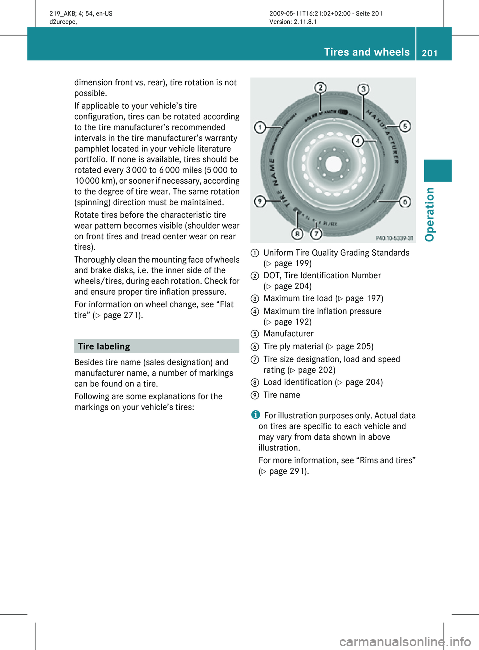
Besides tire name (sales designation) and
manufacturer name, a number of markings
can be found on a tire.
Following are some explanations for the
markings on your vehicle’s tires: :
Uniform Tire Quality Grading Standards
(Y page 199)
; DOT, Tire Identification Number
(Y page 204)
= Maximum tire load ( Y page 197)
? Maximum tire inflation pressure
(Y page 192)
A Manufacturer
B Tire ply material ( Y page 205)
C Tire size designation, load and speed
rating (Y page 202)
D Load identification ( Y page 204)
E Tire name
i For illustration purposes only. Actual data
on tires are specific to each vehicle and
may vary from data shown in above
illustration.
For more information, see “Rims and tires”
(Y page 291). Tires and wheels
201Operation
219_AKB; 4; 54, en-US
d2ureepe, Version: 2.11.8.1 2009-05-11T16:21:02+02:00 - Seite 201 Z
Page 208 of 308
radio, and heater, to the extent that these
items are available as factory-installed
equipment (whether installed or not).
Air pressure
The amount of air inside the tire pressing
outward on each square inch of the tire. Air
pressure is expressed in pounds per square
inch (psi), kilopascal (kPa), or bar.
Aspect ratio
Dimensional relationship between tire
section height and section width expressed
in percentage.
Bar
Metric unit for air pressure. There are
14.5038 pounds per square inch (psi) to
1
bar; there are 100 kilopascals (kPa) to 1 bar.
Bead The tire bead contains steel wires wrapped by
steel cords that hold the tire onto the rim.
Cold tire inflation pressure
Tire inflation pressure when your vehicle has
been sitting for at least 3 hours or driven no
more than 1 mile (1.6 km).
Curb weight
The weight of a motor vehicle with standard
equipment including the maximum capacity
of fuel, oil, and coolant, and, if so equipped,
air conditioning and additional optional
equipment, but without passengers and
cargo.
DOT (Department of Transportation)
A tire branding symbol which denotes the tire
meets requirements of the U.S. Department
of Transportation. GAWR (Gross Axle Weight Rating) The GAWR is the maximum permissible axle
weight.
The gross vehicle weight on each axle
must never exceed the GAWR for the front
and rear axle indicated on the certification
label located on the driver’s door B-pillar.
GVW (Gross Vehicle Weight) The GVW comprises the weight of the vehicle
including fuel, tools, spare wheel, installed
accessories, passengers and cargo and, if
applicable,
trailer tongue load. The GVW must
never exceed the GVWR indicated on the
certification label located on the driver’s door
B-pillar.
GVWR (Gross Vehicle Weight Rating) This is the maximum permissible vehicle
weight of the fully loaded vehicle (weight of
the
vehicle including all options, passengers,
fuel, and cargo and, if applicable, trailer
tongue load). It is indicated on the
certification label located on the driver’s door
B-pillar.
Kilopascal (kPa) Metric unit for air pressure. There are 6.9 kPa
to 1 psi; another metric unit for air pressure
is bar. There are 100 kilopascals (kPa) to
1 bar.
Load index
Numerical code associated with the
maximum load a tire can support.
Maximum load rating
The maximum load in kilograms and pounds
that can be carried by the tire.
Maximum loaded vehicle weight
The sum of curb weight, accessory weight,
total load limit, and production options
weight.206
Tires and wheels
Operation
219_AKB; 4; 54, en-US
d2ureepe,
Version: 2.11.8.1 2009-05-11T16:21:02+02:00 - Seite 206
Page 209 of 308
Maximum permissible tire inflation
pressure
This number is the greatest amount of air
pressure that should ever be put in the tire.
Normal occupant weight
The number of occupants the vehicle is
designed to seat, multiplied by 68 kilograms
(150 lb).
Occupant distribution
The distribution of occupants in a vehicle at
their designated seating positions.
Production options weight
The combined weight of those installed
regular production options weighing over
5 lbs (2.3 kilograms) in excess of those
standard items which they replace, not
previously considered in curb weight or
accessory weight, including heavy duty
brakes, ride levelers, roof rack, heavy duty
battery, and special trim.
PSI (Pounds per square inch)
A standard unit of measure for air pressure.
Recommended tire inflation pressure
The recommended tire inflation pressure for
normal
driving conditions is listed on the Tire
and Loading Information placard located on
the driver’s door B-pillar. It provides best
handling, tread life and riding comfort.
Supplemental information pertaining to
special driving situations can be found on the
tire inflation pressure label on the inside of
the fuel filler flap.
Rim A metal support for a tire or a tire and tube
assembly upon which the tire beads are
seated. Sidewall The portion of a tire between the tread and
the bead.
TIN (Tire Identification Number)
Unique identifier which facilitates efforts by
tire manufacturers to notify purchasers in
recall situations or other safety matters
concerning tires and gives purchasers the
means
to easily identify such tires. The TIN is
comprised of “Manufacturer’s identification
mark”, “Tire size”, “Tire type code” and “Date
of manufacture”.
Tire ply composition and material used This indicates the number of plies or the
number of layers of rubber-coated fabric in
the tire tread and sidewall. Tire
manufacturers also must indicate the ply
materials in the tire and sidewall, which
include steel, nylon, polyester, and others.
Tire speed rating
Part of tire designation (speed symbol);
indicates the speed range for which a tire is
approved.
Total load limit
Rated cargo and luggage load plus
68 kilograms (150 lb) times the vehicle’s
designated seating capacity.
Traction
The adhesive friction of a tire on a surface on
which
it moves. The amount of grip provided.
Tread The portion of a tire that comes into contact
with the road. Tires and wheels
207
Operation
219_AKB; 4; 54, en-US
d2ureepe, Version: 2.11.8.1 2009-05-11T16:21:02+02:00 - Seite 207 Z
Page 212 of 308
Driving instructions
Drive sensibly – save fuel
To save fuel you should:
R Keep tires at the recommended inflation
pressures.
R Remove unnecessary loads.
R Remove roof rack when not in use.
R Allow engine to warm up under low load
use.
R Avoid frequent acceleration and
deceleration.
R Have all maintenance work performed at
the intervals specified in the Maintenance
Booklet and as required by the
Maintenance system. Contact an
authorized Mercedes-Benz Center.
Fuel
consumption is also increased by driving
in cold weather, in stop-and-go traffic, on
short trips and in mountainous areas. Drinking and driving
G
Warning!
Drinking and driving and/or taking drugs and
driving are very dangerous combinations.
Even a small amount of alcohol or drugs can
affect your reflexes, perceptions and
judgment.
The possibility of a serious or even fatal
accident
are greatly increased when you drink
or take drugs and drive.
Do not drink or take drugs and drive or allow
anyone to drive who has been drinking or
taking drugs. Pedals
G
Warning!
Make sure absolutely no objects are
obstructing the pedals’ range of movement.
Keep the driver’s footwell clear of all obstacles. If there are any floormats or
carpets in the footwell, make sure that the
pedals still have sufficient clearance.
During sudden driving or braking maneuvers,
the objects could get caught between the
pedals. You could then no longer brake or
accelerate. This could lead to accidents and
injury.
Power assistance
G
Warning!
There is no power assistance for the steering
and
the brake when the engine is not running.
Steering and braking requires significantly
more effort and you could lose control of the
vehicle and cause an accident as a result.
Do not turn off the engine while the vehicle is
in motion. Brakes
Downhill grades !
When driving down long and steep
grades, relieve the load on the brakes by
shifting into a lower gear to use the
engine’s
braking power. This helps prevent
overheating of the brakes and reduces
wear.
When using the engine’s braking power, a
drive wheel may not spin for an extended
period of time, e.g. on slippery road
surfaces. This may cause serious damage
to the drivetrain which is not covered by the
Mercedes-Benz Limited Warranty.
Continuous or hard braking G
Warning!
Resting your foot on the brake pedal will
cause excessive and premature wear of the
brake pads. 210
Driving instructions
Operation
219_AKB; 4; 54, en-US
d2ureepe,
Version: 2.11.8.1 2009-05-11T16:21:02+02:00 - Seite 210
Page 225 of 308
Vehicle equipment ............................
224
Where will I find ...? .......................... 224
Vehicle status messages in the
multifunction display ....................... 228
What to do if … .................................. 251
Unlocking/locking manually ...........261
Resetting activated NECK-PRO
active front head restraints .............264
Replacing SmartKey batteries ......... 264
Replacing bulbs ................................. 266
Replacing wiper blades ....................270
Flat tire .............................................. 271
Battery ............................................... 278
Jump starting .................................... 280
Towing the vehicle ............................281
Fuses .................................................. 284 223Practical hints
219_AKB; 4; 54, en-US
d2ureepe,
Version: 2.11.8.1 2009-05-11T16:21:02+02:00 - Seite 223
Page 228 of 308
Before placing the jack back into the vehicle
tool kit:
X
Fully collapse the jack.
X Fold in the crank handle (storage position). Spare wheel
G
Observe Safety notes, see page 271.
The spare wheel is located in the space
underneath the trunk floor.
X Removing: Open the trunk (Y page 71).
X Lift the trunk floor using the floor handle.
X Engage the floor handle on the upper trunk
lip.
! To prevent damage, always disengage the
floor handle from the upper trunk lip and
lower the trunk floor before closing the
trunk.
Vehicles with Minispare wheel X
Remove the luggage box ( Y page 227).X
Remove spare wheel mounting ; by
turning it counterclockwise.
X Remove spare wheel :.
For information on mounting the spare wheel,
see “Flat tire” ( Y page 271). Storing the spare wheel after use
X
Place spare wheel : in the spare wheel
well (Y page 226).
X Secure spare wheel : by turning spare
wheel mounting ; clockwise
(Y page 226).
Vehicles with spare wheel with
collapsible tire X
Remove the storage well casing
(Y page 225). :
Spare wheel
; Tensioning strap 15
= Retaining screw
? Storage well casing base
X Remove storage well casing base ?.
X Remove retaining screw = by turning it
counterclockwise.
X Remove spare wheel :.
For information on mounting the spare wheel,
see “Flat tire” ( Y page 271).
Storing the spare wheel after use
If you wish to store the spare wheel after use,
carry out the following steps. Otherwise, the
spare wheel may not fit the spare wheel well.
! Make sure the spare wheel is dry before
storing it.
15 Vehicles with 19" spare wheel only. 226
Where will I find ...?Practical hints
219_AKB; 4; 54, en-US
d2ureepe,
Version: 2.11.8.1 2009-05-11T16:21:02+02:00 - Seite 226
Page 229 of 308
X
Unscrew the valve cap from the valve of the
collapsible tire.
X Unscrew the valve insert from the valve
using the valve extractor integrated in the
valve cap.
X Allow the air to escape.
i It may take a few minutes for the
collapsible tire to deflate completely.
X Screw the valve insert back into the valve.
X Screw the valve cap back onto the valve.
i Vehicles with 19" spare wheel only:
Before placing the spare wheel in the spare
wheel well fasten tensioning straps, see
“Compressing the collapsible tire”
(Y page 227).
X Place spare wheel : into the spare wheel
well (Y page 226).
X Secure spare wheel : by turning retaining
screw = clockwise (Y page 226).
Compressing the collapsible tire
This description applies to vehicles with
19" spare wheel only.
The collapsible tire on a 19" spare wheel must
be compressed with two tensioning straps
before you can store it in the spare wheel well. X
Extend the tensioning strap by pulling the
slider.
X Place tensioning strap around the spare
wheel rim and collapsible tire with the
buckle facing the inside of the rim. X
Close the buckle.
X Pull the loose end of the tensioning strap.
The tensioning strap must be pulled as tight
as possible. Luggage box
Vehicles with spare wheel with collapsible tire
are not equipped with a luggage box.
X Removing: Open the trunk (Y page 71).
X Lift the trunk floor using the floor handle.
X Engage the floor handle on the upper trunk
lip.
! To prevent damage, always disengage the
floor handle from the upper trunk lip and
lower the trunk floor before closing the
trunk. X
Turn fastening clips : to the left upwards
from the fastening bolts.
X Lift luggage box ; in the area of the
fastening bolts and remove it from the
trunk.
X Installing: Insert the luggage box into the
trunk so that the fastening clips are in line
with the fastening bolts. Where will I find ...?
227Practical hints
219_AKB; 4; 54, en-US
d2ureepe, Version: 2.11.8.1 2009-05-11T16:21:02+02:00 - Seite 227 Z