2011 MERCEDES-BENZ C-CLASS ESTATE radio
[x] Cancel search: radioPage 368 of 401
i
If the wheel positions on the vehicle are
interchanged, the tyre pressures may be
displayed for the wrong positions for a
short time. This is rectified after a few
minutes of driving, and the tyre pressures
are displayed for the correct positions.
Restarting the tyre pressure monitor When you restart the tyre pressure monitor,
all existing warning messages are deleted and
the warning lamps go out. The monitor uses
the currently set tyre pressures as the refer-
ence values for monitoring. In most cases, the
tyre pressure monitor will automatically
detect the new reference values after you
have changed the tyre pressure.
i For an overview of the menus, see
(Y page 230).
If you wish to define the new reference values
manually:
X Use the table on the inside of the fuel filler
flap to ensure that the tyre pressure is set
correctly in all four tyres for the current
operating conditions.
Also observe the notes in the section on
tyre pressures (Y page 361).
X Make sure that the key is in position 2in
the ignition lock.
X Press the =or; button on the steer-
ing wheel to select the Service menu.
X Press the 9or: button to select
Tyre pressure .
X Press the abutton.
The multifunction display shows the cur-
rent tyre pressure of the individual tyres or
the Tyre pressures will be dis‐ played after a few minutes of driv‐
ing message.
X Press the :button.
The Use current pressures as new reference values message appears in
the multifunction display. If you wish to confirm the restart:
X
Press the abutton.
The Tyre press. monitor restarted message appears in the multifunction dis-
play.
After you have driven for a few minutes, the
system checks whether the current tyre
pressures are within the specified range.
The new tyre pressures are then accepted
as reference values and monitored.
If you wish to cancel the restart:
X Press the %button.
The tyre pressure values stored at the last
restart will continue to be monitored.
Radio type approval for the tyre pres-
sure monitor In certain countries, a radio type approval for
the tyre pressure monitor may be required.
The radio type approval number for the tyre
pressure monitor can be found online at:
http://www.mercedes-benz.de/
betriebsanleitung.
Changing
awheel Flat tyre
The "Breakdown assistance" section
(Y page 337) contains information and notes
on how to deal with a fla ttyre. It also provides
instructions on changing a wheel or fitting the
spare wheel or emergency spare wheel. Interchanging the wheels
G
WARNING
Interchange the front and rear wheels only if
they have the same dimensions, fo rexample
size, offset, etc.
After every wheel interchange/change, have
the tightening torque checked at a qualified
specialist workshop tha thas the necessary
specialist knowledge and tools to carry out Changing
awheel
365Wheels and tyres
Z
Page 380 of 401
H
Environmental note
Daimler AG also supplies reconditioned
assemblies and parts which are of the same
quality as new parts. For these, the same war-
ranty applies as for new parts.
Always specify the vehicle identification num-
ber (VIN) (Y page 379) and the engine num-
ber (Y page 379) when ordering genuine
Mercedes-Ben zparts. Vehicle electronics
Tampering with the engine electron-
ics
G
WARNING
Only have work on the engine electronics and
related components carried out at a qualified
specialist workshop which has the necessary
specialist knowledge and tools to carry out
the work required. Mercedes-Benz recom-
mends that you use a Mercedes-Ben zService
Centre for this purpose. In particular, work
relevant to safety or on safety-related sys-
tems must be carried out at a qualified spe-
cialist workshop. Otherwise, the vehicle's
roadworthiness could be affected.
! Only have maintenance work on the
engine electronics and its associated parts,
such as control units, sensors and connec-
tor leads, carried out at a qualified special-
ist workshop, e.g. a Mercedes-Benz Service
Centre. Vehicle componentsm ay other-
wise wear more quickly and the vehicle's
operating permit may be invalidated. Retrofitting of two-way radios and
mobile phones (RF transmitters)
Use the Technical Specification
ISO/TS 21609 30
implementation regulation
when retrofitting RF (radio frequency) trans-
mitters. If your vehicle has fittings for two-way radio
equipment, use the power supply or aerial
connections intended for use with the basic
wiring. Be sure to observe the manufacturer's
additional instructions when installing the fit-
tings.
!
Have aftermarket radio frequency trans-
mitting equipmen tinstalled at a qualified
specialist workshop .Mercedes-Benzr ec-
ommends that you use a Mercedes-Benz
Service Centre for this purpose.
The transmission output at the aerial base
must not exceed the maximum values below. Waveband Maximum trans-
mission output
(PEAK)
Short wave
(f < 54 MHz) 100 W
4 m waveband 30 W
2 m waveband 50 W
Trunked radio/Tetra 35 W
70 cm waveband 35 W
GSM 900/AMPS 10 W
GSM 1800 10 W
UMTS 10 W
The following aerial positions may be used if
RF transmitters have been properly installed:
30 ISO/TS 2160 9–Technical Specification for Road Vehicles (EMC) guidelines for installation of aftermarket
radio frequency transmitting equipment. Vehicle electronics
377Technical data Z
Page 381 of 401
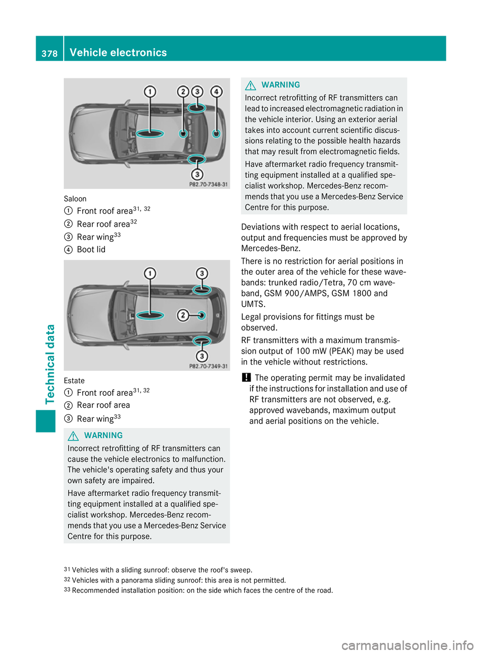
Saloon
:
Front roof area 31, 32
; Rear roof area 32
= Rear wing 33
? Boot lid Estate
:
Front roof area 31, 32
; Rear roof area
= Rear wing 33 G
WARNING
Incorrect retrofitting of RF transmitters can
cause the vehicle electronics to malfunction.
The vehicle's operating safety and thus your
ow ns afety are impaired.
Have aftermarket radio frequency transmit-
ting equipment installed at a qualified spe-
cialis tworkshop. Mercedes-Benz recom-
mends that you use a Mercedes-Benz Service
Centre for this purpose. G
WARNING
Incorrect retrofitting of RF transmitters can
lead to increased electromagnetic radiation in
the vehicle interior. Using an exterior aerial
takes into account current scientific discus-
sions relating to the possible health hazards
that may result from electromagnetic fields.
Have aftermarket radio frequency transmit-
ting equipment installed at a qualified spe-
cialist workshop. Mercedes-Benz recom-
mends that you use a Mercedes-Benz Service
Centre for this purpose.
Deviations with respect to aerial locations,
output and frequencies must be approved by
Mercedes-Benz.
There is no restriction for aerial positions in
the outer area of the vehicle for these wave-
bands: trunked radio/Tetra, 70 cm wave-
band, GSM 900/AMPS, GSM 1800 and
UMTS.
Legal provisions for fittings must be
observed.
RF transmitters with a maximum transmis-
sion output of 100 mW (PEAK) may be used
in the vehicle without restrictions.
! The operating permit may be invalidated
if the instructions for installation and use of
RF transmitters are not observed, e.g.
approved wavebands, maximum output
and aerial positions on the vehicle.
31 Vehicles with a sliding sunroof: observe the roof's sweep.
32 Vehicles with a panorama sliding sunroof: this area is not permitted.
33 Recommended installation position: on the side which faces the centre of the road. 378
Vehicle electronicsTechnical data
Page 392 of 401
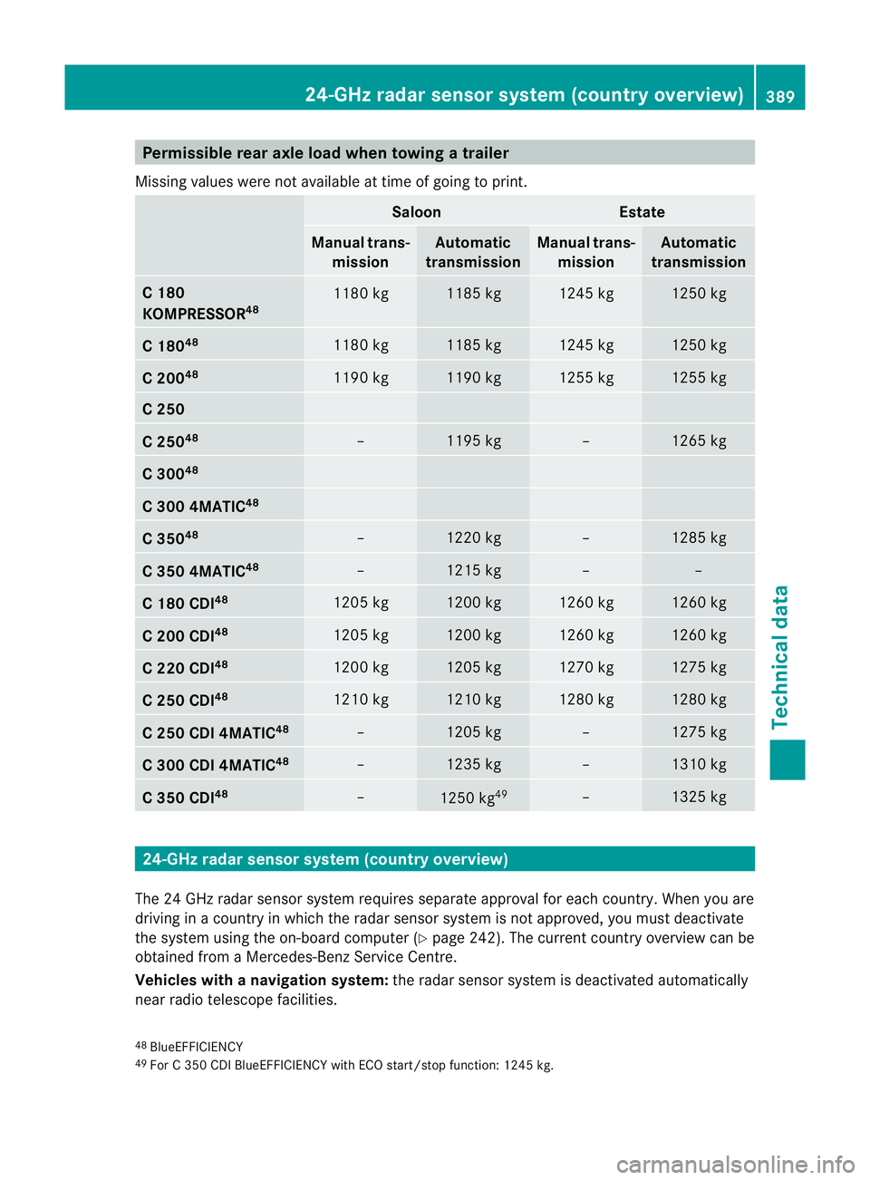
Permissible rear axle load when towing
atrailer
Missing values were not availabl eattime of going to print. Saloon Estate
Manual trans-
mission Automatic
transmission Manual trans-
mission Automatic
transmission C 180
KOMPRESSOR
48 1180 kg 1185 kg 1245 kg 1250 kg
C 180
48 1180 kg 1185 kg 1245 kg 1250 kg
C 200
48 1190 kg 1190 kg 1255 kg 1255 kg
C 250
C 250
48 – 1195 kg – 1265 kg
C 300
48 C 300 4MATIC
48 C 350
48 – 1220 kg – 1285 kg
C 350 4MATIC
48 – 1215 kg – –
C 180 CDI
48 1205 kg 1200 kg 1260 kg 1260 kg
C 200 CDI
48 1205 kg 1200 kg 1260 kg 1260 kg
C 220 CDI
48 1200 kg 1205 kg 1270 kg 1275 kg
C 250 CDI
48 1210 kg 1210 kg 1280 kg 1280 kg
C 250 CDI 4MATIC
48 – 1205 kg – 1275 kg
C 300 CDI 4MATIC
48 – 1235 kg – 1310 kg
C 350 CDI
48 –
1250 kg
49 – 1325 kg
24-GHz radar sensor system (country overview)
The 24 GHz radar sensor system requires separate approval for each country. When you are
driving in a country in which the radar sensor system is not approved, you must deactivate
the system using the on-board computer (Y page 242). The current country overview can be
obtained from a Mercedes-Benz Service Centre.
Vehicles with anavigation system: the radar sensor system is deactivated automatically
near radio telescope facilities.
48 BlueEFFICIENCY
49 For C 350 CDI BlueEFFICIENCY with ECO start/stop function: 1245 kg. 24-GHz radar sensor system (country overview)
389Technical data Z
Page 393 of 401
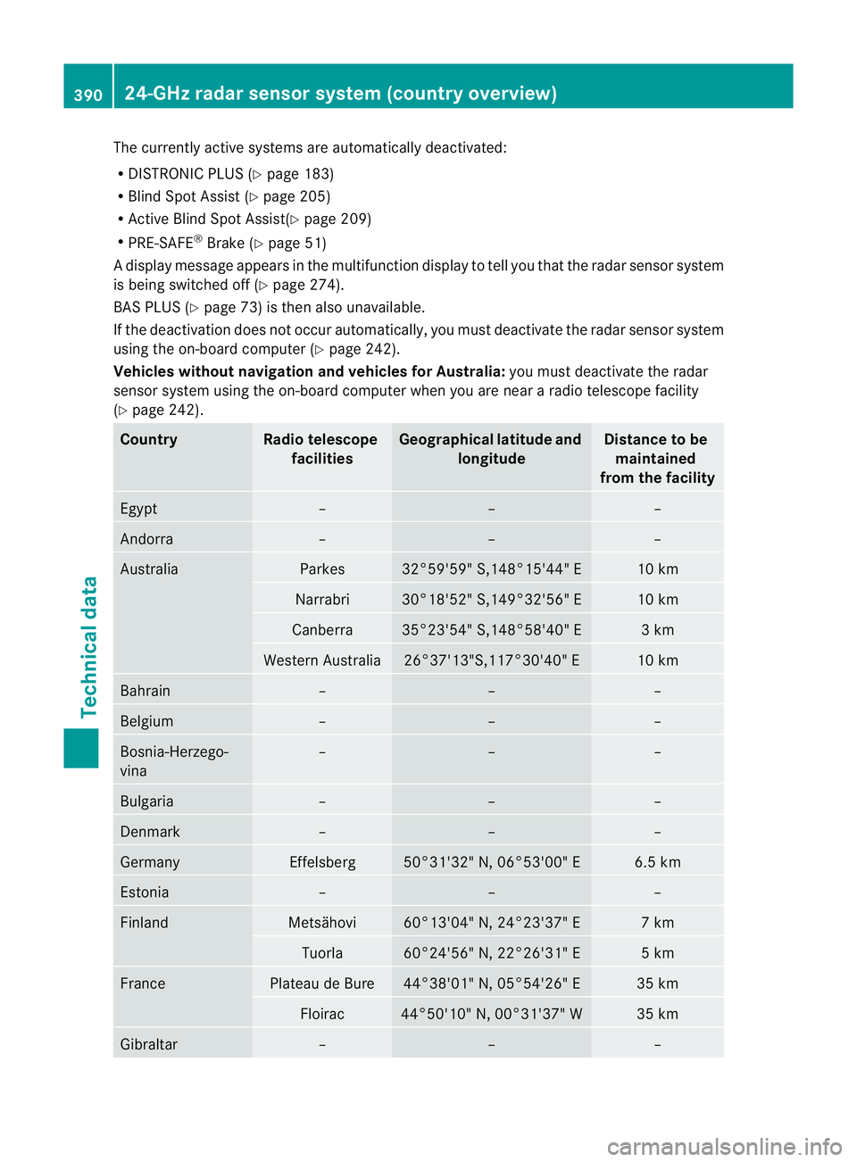
The currently active systems are automatically deactivated:
R
DISTRONIC PLUS (Y page 183)
R Blind Spot Assist (Y page 205)
R Active Blind Spot Assist(Y page 209)
R PRE-SAFE ®
Brake (Y page 51)
Ad isplay message appears in the multifunction display to tell you that the radar sensor system
is being switched off (Y page 274).
BAS PLUS (Y page 73) is the nalso unavailable.
If the deactivation does not occur automatically, you must deactivate the radar sensor system
using the on-board computer (Y page 242).
Vehicles withou tnavigation and vehicles for Australia: you must deactivate the radar
sensor system using the on-board computer whe nyou are near a radio telescope facility
(Y page 242). Country Radio telescope
facilities Geographical latitude and
longitude Distance to be
maintained
from the facility Egypt – – –
Andorra – – –
Australia Parkes 32°59'59" S,148°15'44" E 10 km
Narrabri 30°18'52" S,149°32'56" E 10 km
Canberra 35°23'54" S,148°58'40" E 3 km
Western Australia 26°37'13"S,117°30'40" E 10 km
Bahrain – – –
Belgium – – –
Bosnia-Herzego-
vina – – –
Bulgaria – – –
Denmark – – –
Germany Effelsberg 50°31'32" N, 06°53'00" E 6.5 km
Estonia – – –
Finland Metsähovi 60°13'04" N, 24°23'37" E 7 km
Tuorla 60°24'56" N, 22°26'31" E 5 km
France Plateau de Bure 44°38'01" N, 05°54'26" E 35 km
Floirac 44°50'10" N, 00°31'37" W 35 km
Gibraltar – – –390
24-GHz radar sensor system (country overview)Technical data
Page 394 of 401
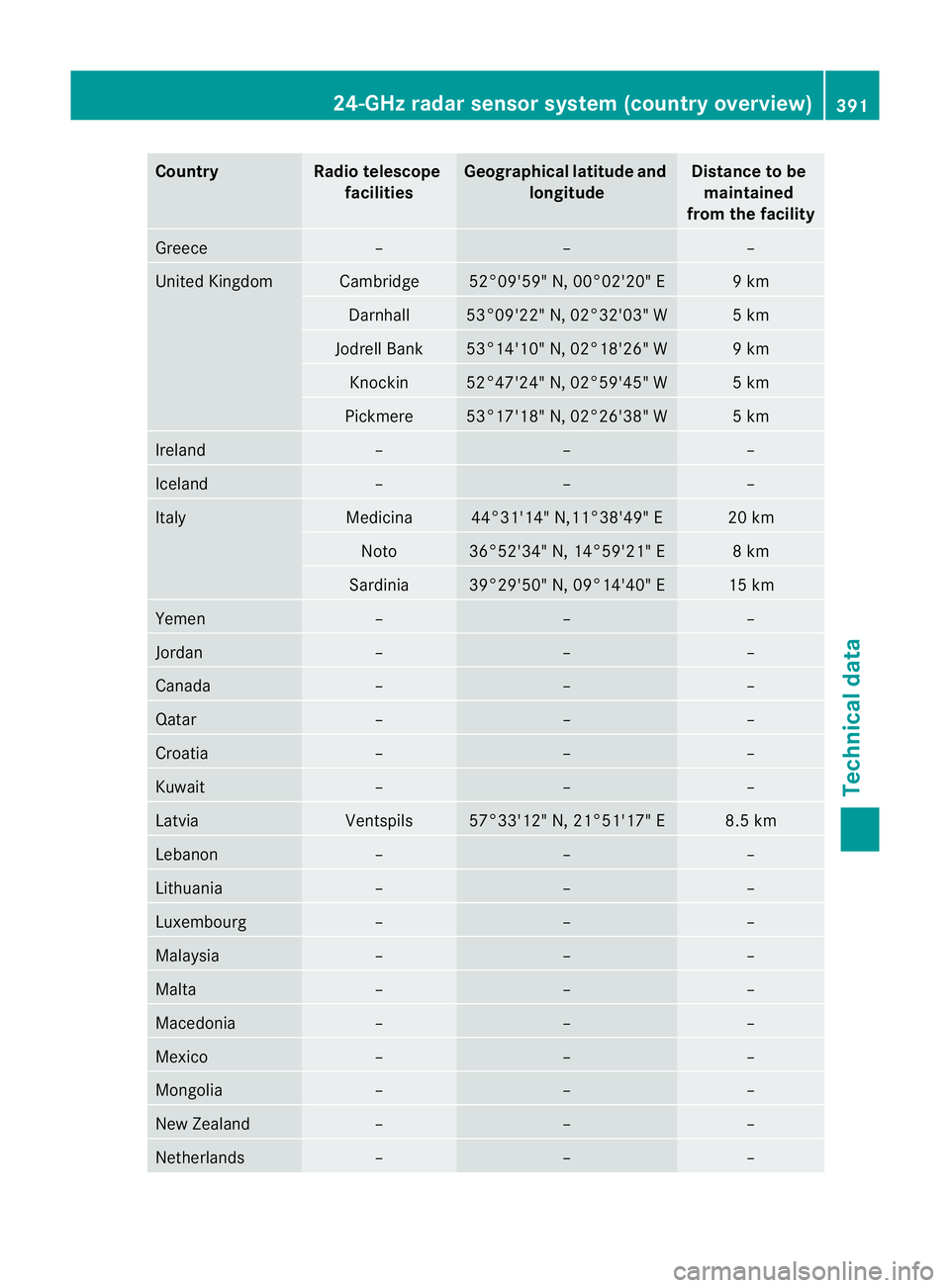
Country Radio telescope
facilities Geographica
llatitude and
longitude Distance to be
maintained
from the facility Greece – – –
United Kingdom Cambridge 52°09'59" N, 00°02'20" E 9 km
Darnhall 53°09'22" N, 02°32'03" W 5 km
Jodrell Bank 53°14'10" N, 02°18'26" W 9 km
Knockin 52°47'24" N, 02°59'45" W 5 km
Pickmere 53°17'18" N, 02°26'38" W 5 km
Ireland – – –
Iceland – – –
Italy Medicina 44°31'14" N,11°38'49" E 20 km
Noto 36°52'34" N, 14°59'21" E 8 km
Sardinia 39°29'50" N, 09°14'40" E 15 km
Yemen – – –
Jordan – – –
Canada – – –
Qatar – – –
Croatia – – –
Kuwait – – –
Latvia Ventspils 57°33'12" N, 21°51'17" E 8.5 km
Lebanon – – –
Lithuania – – –
Luxembourg – – –
Malaysia – – –
Malta – – –
Macedonia – – –
Mexico – – –
Mongolia – – –
New Zealand – – –
Netherlands – – –24-GHz radar sensor system (country overview)
391Technical data Z
Page 395 of 401
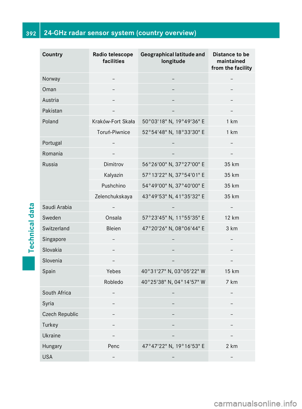
Country Radio telescope
facilities Geographica
llatitude and
longitude Distance to be
maintained
from the facility Norway – – –
Oman – – –
Austria – – –
Pakistan – – –
Poland Kraków-Fort Skała 50°03'18" N, 19°49'36" E 1 km
Toruń-Piwnice 52°54'48" N, 18°33'30" E 1 km
Portugal – – –
Romania – – –
Russia Dimitrov 56°26'00" N, 37°27'00" E 35 km
Kalyazin 57°13'22" N, 37°54'01" E 35 km
Pushchino 54°49'00" N, 37°40'00" E 35 km
Zelenchukskaya 43°49'53" N, 41°35'32" E 35 km
Saudi Arabia – – –
Sweden Onsala 57°23'45" N, 11°55'35" E 12 km
Switzerland Bleien 47°20'26" N, 08°06'44" E 3 km
Singapore – – –
Slovakia – – –
Slovenia – – –
Spain Yebes 40°31'27" N, 03°05'22" W 15 km
Robledo 40°25'38" N, 04°14'57" W 7 km
South Africa – – –
Syria – – –
Czech Republic – – –
Turkey – – –
Ukraine – – –
Hungary Penc 47°47'22" N, 19°16'53" E 2 km
USA – – –392
24-GHz radar sensor system (country overview)Technical data
Page 396 of 401
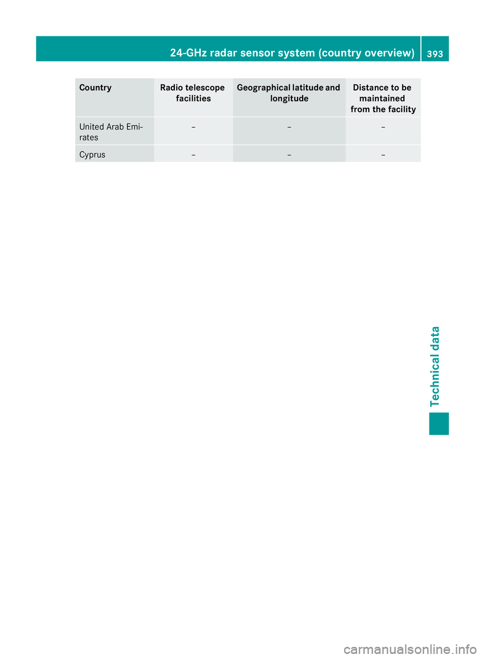
Country Radio telescope
facilities Geographica
llatitude and
longitude Distance to be
maintained
from the facility United Arab Emi-
rates – – –
Cyprus – – –24-GHz radar sensor system (country overview)
393Technical data Z