2011 MERCEDES-BENZ C-CLASS ESTATE lock
[x] Cancel search: lockPage 322 of 401
More information on suitable mobile phones,
mobile phone brackets and on connecting
Bluetooth ®
capable mobile phones to Audio
20 or COMAND Online can be obtained:
R at your Mercedes-Benz Service Centre
R on the Internet at http://www.mercedes-
benz.com/connect
i The functions and services available when
you use the phone depend on your mobile
phone model and service provider.
Inserting the mobile phone X
Open the telephone compartment
(Y page 303).
X Place the mobile phone bracket into the
pre-installed bracket (see the separate
mobile phone bracket installation instruc-
tions).
X Insert the mobile phone into the mobile
phone bracket (see the separate mobile
phone bracket installation instructions).
If the mobile phone is inserted in the mobile
phone bracket, you can speak to the person
you are calling using the hands-free system.
i On some mobile phone brackets, you first
have to connect the mobile phone via Blue-
tooth ®
to a mobile phone bracket (see the
separate operating instructions for the
mobile phone bracket).
On these mobile phone brackets, the
mobile phone does not have to be inserted
into the bracket for you to be able to use
the telephone functions. In this case, the
charging function and aerial function are
not available.
Operating the mobile phone You can operate the telephone using the
6 and~ buttons on the luxury multi-
function steering wheel. You can operate
other mobile phone functions via the on-
board computer (Y page 235). If you take the key out of the ignition lock, the
mobile phone stays on but you can no longer
use the hands-free system.
If you are making a call and you would like to
take the key out of the ignition lock, first
remove the mobile phone from the bracket.
Otherwise, the call will be ended.
i When a mobile phone bracket is used that
is connected to the mobile phone via Blue-
tooth ®
: if you want to continue a call in
"Private mode", you have to perform the
necessary steps on the mobile phone (see
the separate mobile phone operating
instructions).
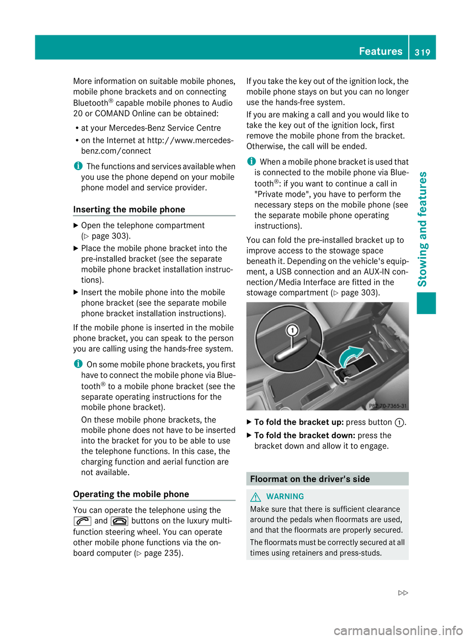
You can fold the pre-installed bracket up to
improve access to the stowage space
beneath it. Depending on the vehicle's equip-
ment, a USB connection and an AUX-IN con-
nection/Media Interface are fitted in the
stowage compartmen t(Ypage 303). X
To fold the bracket up: press button:.
X To fold the bracket down: press the
bracket down and allow it to engage. Floormat on the driver's side
G
WARNING
Make sure that there is sufficient clearance
around the pedals when floormats are used,
and that the floormats are properly secured.
The floormats must be correctly secured at all
times using retainers and press-studs. Features
319Stowing and features
Z
Page 325 of 401
Useful information
i This Owner's Manual describes all models
and all standard and optional equipment
available to your vehicle at the time of pub-
lication of the Owner's Manual. Country-
specific deviations are possible. Please
note that your vehicle may not be equipped
with all features described. This also
applies to safety-relevan tsystems and
functions.
i Please read the information on qualified
specialist workshops (Y page 28).Engine compartment
Bonnet
Opening the bonnet G
WARNING
Do no tpull the release leve rwhile the vehicle
is in motion. If you do so, the bonnet may open
up and block your view. G
WARNING
There is a risk of injury if the bonnet is open,
even if the engine is not running.
Some engine components can become very
hot.
To avoid the risk of burns, only touch those
components described in the Owner's Manual
and observe the relevant safety notes. G
WARNING
The radiator fan between the radiator and the
engine can start automatically, even if the key
has been removed from the ignition lock. For
this reason, you must not reach into the fan
rotation area. You could otherwise be injured. Vehicles with
apetrol engine: The elec-
tronic ignitio nsystem uses high voltage. For
this reason, you mus tnever touch ignition
system components (ignition coil, ignition
cables, spark plug connectors or test socket)
while:
R the engine is running
R the engine is being started
R the ignition is switched on and the engine
is being cranked by hand
You could otherwise suffer an electric shock
and be seriously or even fatally injured.
Vehicles with adiesel engine: The elec-
tronic injection control uses high voltage. For
this reason, you must never touch injection
system components while:
R the engine is running
R the engine is being started
R the ignition is switched on
You could otherwise suffer an electric shock
and be seriously or even fatally injured.
X Make sure that the windscreen wipers are
switched off. G
WARNING
The windscreen wipers and wiper linkage
could be set in motion.
When the bonnet is open, you or others could
be injured by the wiper linkage.
Make sure that the windscreen wipers are
switched off. Remove the key or make sure
that no ignition position has been selected
with KEYLESS-GO. All indicator lamps must be
off in the instrument panel. 322
Engine compartmentMaintenance and care
Page 327 of 401
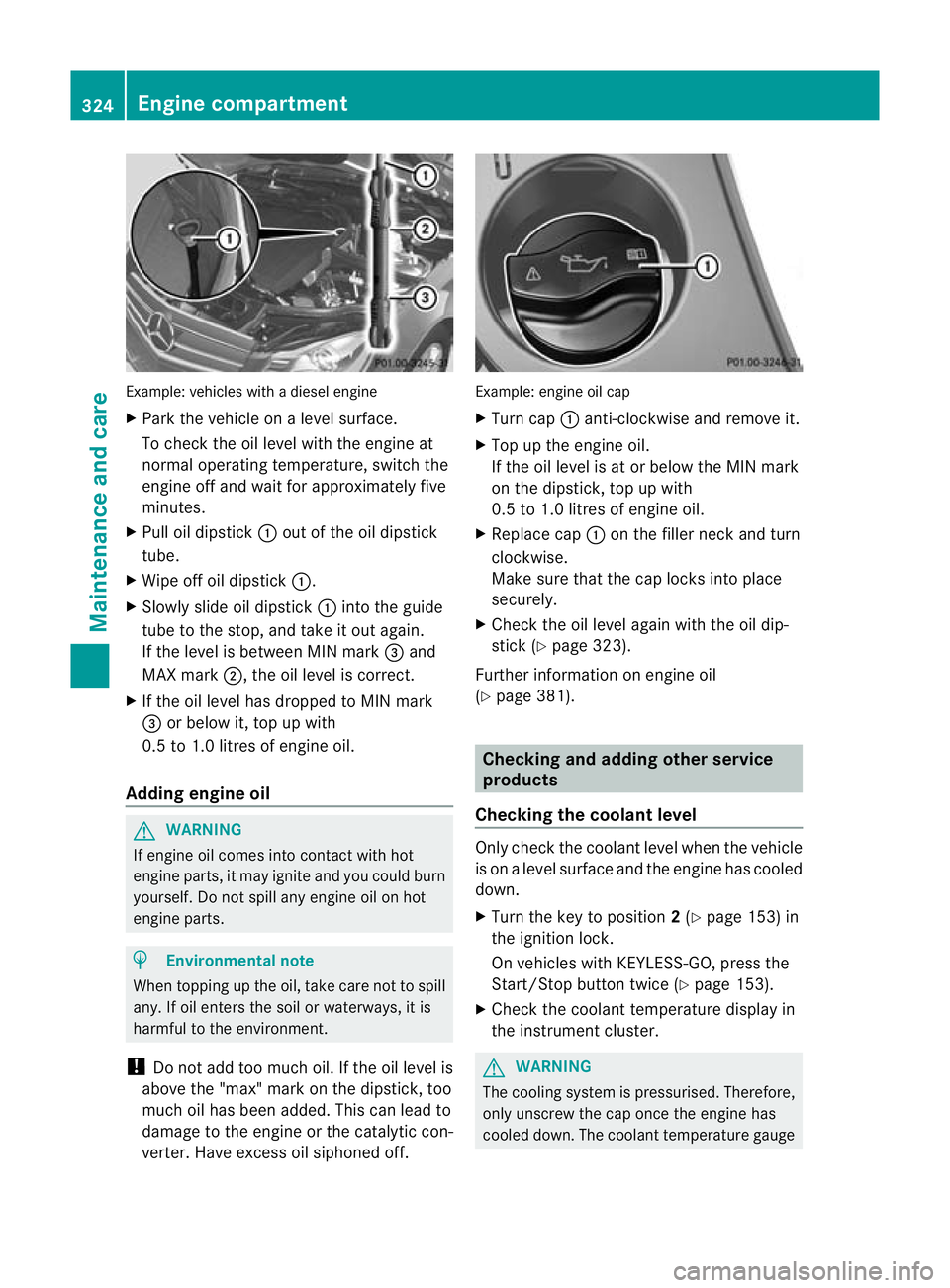
Example: vehicles with a diesel engine
X
Park the vehicle on a level surface.
To check the oil level with the engine at
normal operating temperature, switch the
engine off and wait for approximately five
minutes.
X Pull oil dipstick :outoft he oil dipstick
tube.
X Wipe off oil dipstick :.
X Slowly slide oil dipstick :into the guide
tube to the stop, and take it out again.
If the level is between MIN mark =and
MAX mark ;, the oil level is correct.
X If the oil level has dropped to MIN mark
= or below it, top up with
0.5 to 1.0 litres of engine oil.
Adding engine oil G
WARNING
If engine oil comes into contact with hot
engine parts, it may ignite and you could burn
yourself. Do not spill any engine oil on hot
engine parts. H
Environmental note
When topping up the oil, take care not to spill
any. If oil enters the soil or waterways, it is
harmful to the environment.
! Do not add too much oil. If the oil level is
above the "max" mark on the dipstick, too
much oil has been added. This can lead to
damage to the engine or the catalytic con-
verter. Have excess oil siphoned off. Example: engine oil cap
X
Turn cap :anti-clockwise and remove it.
X Top up the engine oil.
If the oil level is at or below the MIN mark
on the dipstick, top up with
0.5 to 1.0 litres of engine oil.
X Replace cap :on the filler neck and turn
clockwise.
Make sure that the cap locks into place
securely.
X Check the oil level again with the oil dip-
stick (Y page 323).
Further information on engine oil
(Y page 381). Checking and adding other service
products
Checking the coolant level Only check the coolant level when the vehicle
is on a level surface and the engine has cooled
down.
X Turn the key to position 2(Y page 153) in
the ignition lock.
On vehicles with KEYLESS-GO, press the
Start/Stop button twice (Y page 153).
X Check the coolant temperature display in
the instrument cluster. G
WARNING
The cooling system is pressurised. Therefore,
only unscrew the cap once the engine has
cooled down. The coolant temperature gauge 324
Engine compartmentMaintenance and care
Page 328 of 401
must display less than 70
†.Otherwise, you
could be scalded if hot coolant escapes. X
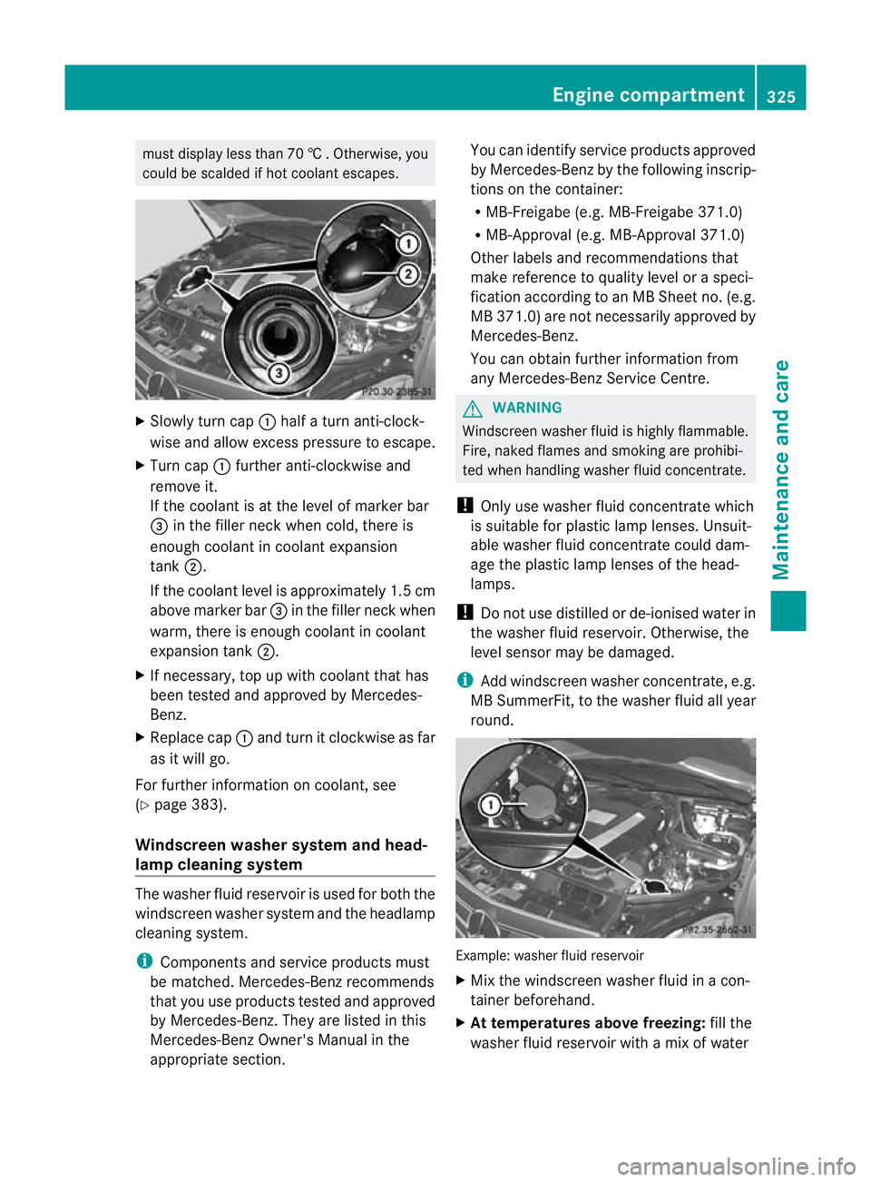
Slowly tur ncap : half a turn anti-clock-
wise and allow excess pressure to escape.
X Turn cap :further anti-clockwise and
remove it.
If the coolant is at the level of marker bar
= in the fille rneck when cold, there is
enough coolant in coolant expansion
tank ;.
If the coolant level is approximately 1.5 cm
above marker bar =in the filler neckw hen
warm, there is enough coolant in coolant
expansion tank ;.
X If necessary, top up with coolant that has
been tested and approved by Mercedes-
Benz.
X Replace cap :and turn it clockwise as far
as it will go.
For further information on coolant, see
(Y page 383).
Windscreen washer system and head-
lamp cleaning system The washer fluid reservoir is used for both the
windscreen washer system and the headlamp
cleaning system.
i
Components and service products must
be matched. Mercedes-Benz recommends
that you use products tested and approved
by Mercedes-Benz. They are listed in this
Mercedes-Ben zOwner's Manual in the
appropriate section. You can identify service products approved
by Mercedes-Ben
zby th efollowing inscrip-
tions on the container:
R MB-Freigabe (e.g. MB-Freigabe 371.0)
R MB-Approval (e.g. MB-Approval 371.0)
Other labels and recommendations that
make reference to quality level or a speci-
fication according to an MB Sheet no. (e.g.
MB 371.0) are not necessarily approved by
Mercedes-Benz.
You can obtain further information from
any Mercedes-Benz Service Centre. G
WARNING
Windscreen washer fluid is highly flammable.
Fire, naked flames and smoking are prohibi-
ted when handling washer fluid concentrate.
! Only use washer fluid concentrate which
is suitable for plastic lamp lenses. Unsuit-
able washer fluid concentrate could dam-
age the plastic lamp lenses of the head-
lamps.
! Do not use distilled or de-ionised water in
the washer fluid reservoir. Otherwise, the
level sensor may be damaged.
i Add windscreen washer concentrate, e.g.
MB SummerFit, to the washer fluid all year
round. Example: washer fluid reservoir
X
Mix the windscreen washer fluid in a con-
tainer beforehand.
X At temperatures above freezing: fill the
washer fluid reservoir with amix of water Engine compartment
325Maintenance and care Z
Page 332 of 401
X
Remove coolant, brake fluid, tree resin,
oils, fuels and greases by rubbing gently
with a cloth soaked in petroleum ether or
lighte rfluid.
X Use tar remover to remove tar stains.
X Use silicone remover to remove wax.
! Do not affix:
R stickers
R films
R magnetic plates or similar items
to painted surfaces. You could otherwise
damage the paintwork.
Care and treatment of matt paintwork If your vehicle has a clear mat
tfinish, observe
the following instructions in order to avoid
damage to the paintwork due to incorrect
care.
These notes also apply to light alloy wheels
with a clear mat tfinish.
! Neve rpolish the vehicle or the light alloy
wheels. Polishing makes the paintwork
shiny.
! The following may cause the paint to
become shiny and thus reduce the matt
effect:
R Vigorous rubbing with unsuitable mate-
rials.
R Frequent use of car washes.
R Washing the vehicle in direct sunlight.
! Never use paint cleaner, buffing or pol-
ishing products, or gloss preserver, e.g.
wax. These products are only suitable for
high-gloss surfaces. Their use on vehicles
with matt finish leads to considerable sur-
face damage (shiny, spotted areas).
Always have paintwork repairs performed
at a qualified specialist workshop, e.g. a
Mercedes-Benz Service Centre.
! Do not use wash programs with a hot wax
treatment under any circumstances. i
The vehicle should preferably be washed
by hand using a soft sponge, car shampoo
and plenty of water.
i Use only insect remover and car shampoo
from the range of recommended and
approved Mercedes-Benz care products.
Cleaning the windows G
WARNING
Switch off the windscreen wipers and remove
the key from the ignition lock before cleaning
the windscreen or the wiper blades. On vehi-
cles with KEYLESS-GO, press the Start/Stop
button repeatedly until all indicator lamps in
the instrument cluster have gone off. The
windscreen wipers could otherwise move and
injure you.
! Only fold the windscreen wipers away
from the windscreen when vertical. Other-
wise, you will damage the bonnet.
X Clean the inside and outside of the win-
dows with a damp cloth and a cleaning
agent that is recommended and approved
by Mercedes-Benz.
! Do not use dry cloths, abrasive products,
solvents or cleaning agents containing sol-
vents to clean the inside of the windows.
Do not touch the insides of the windows
with hard objects, e.g. an ice scraper or
ring. There is otherwise a risk of damaging
the windows.
! Clean the water drainage channels of the
windscreen and the rear window at regular
intervals. Deposits such as leaves, petals
and pollen may under certain circumstan-
ces prevent water from draining away.T his
can lead to corrosion damage and damage
to electronic components.
Cleaning the wiper blades G
WARNING
Switch off the windscreen wipers and remove
the key from the ignition lock before cleaning Care
329Maintenance and care
Z
Page 337 of 401
Useful information
i This Owner's Manual describes all models
and all standard and optional equipment
available to your vehicle at the time of pub-
lication of the Owner's Manual. Country-
specific deviations are possible. Please
note that your vehicle may not be equipped
with all features described. This also
applies to safety-relevan tsystems and
functions.
i Please read the information on qualified
specialist workshops (Y page 28).Where will I find...?
Warning triangle
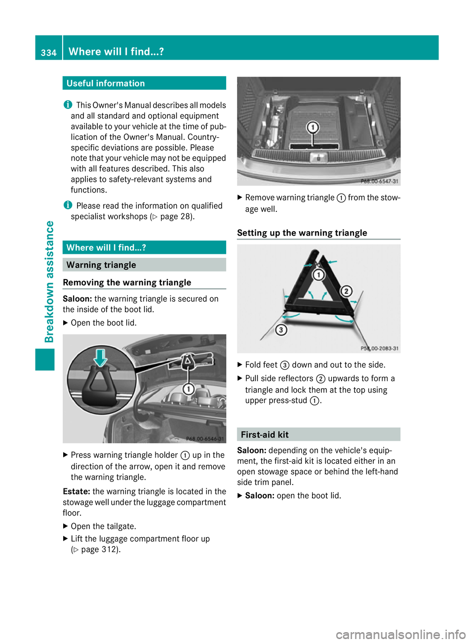
Removing the warning triangle Saloon:
the warning triangle is secured on
the inside of the boo tlid.
X Open the boot lid. X
Press warning triangle holder :up in the
direction of the arrow, open it and remove
the warning triangle.
Estate: the warning triangle is located in the
stowage well under the luggage compartment
floor.
X Open the tailgate.
X Lift the luggage compartmen tfloor up
(Y page 312). X
Remove warning triangle :fromt he stow-
age well.
Setting up the warning triangle X
Fold feet =down and out to the side.
X Pull side reflectors ;upwards to form a
triangle and lock them at the top using
upper press-stud :. First-aid kit
Saloon: depending on the vehicle's equip-
ment, the first-aid kit is located either in an
open stowage space or behind the left-hand
side trim panel.
X Saloon: open the boot lid. 334
Where will I find...?Breakdown assistance
Page 340 of 401
X
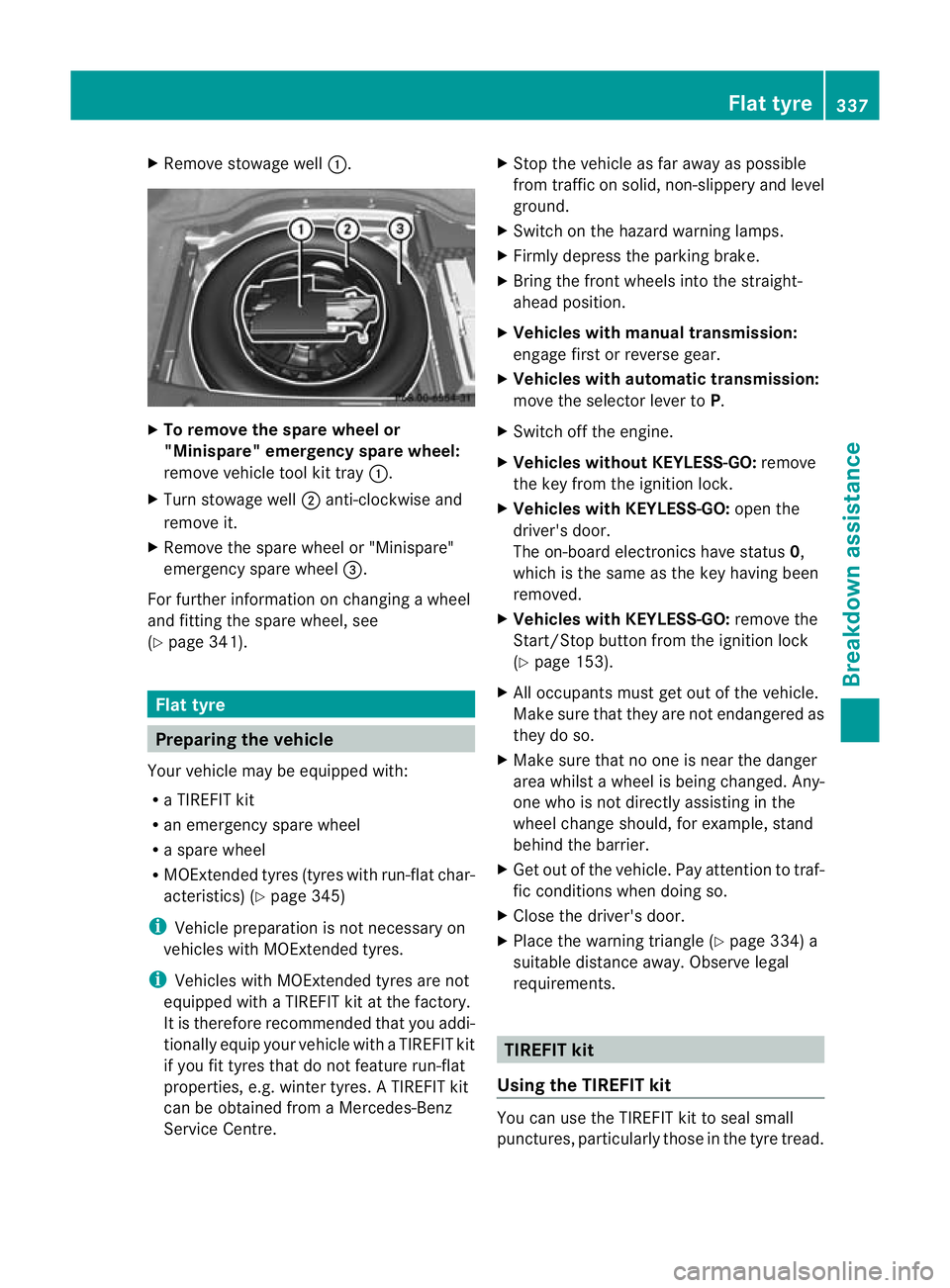
Remove stowage well :.X
To remove the spare wheel or
"Minispare "emergency spare wheel:
remove vehicle tool kit tray :.
X Turn stowage well ;anti-clockwise and
remove it.
X Remove the spare wheel or "Minispare"
emergency spare wheel =.
For further information on changing a wheel
and fitting the spare wheel, see
(Y page 341). Flat tyre
Preparing the vehicle
Your vehicle may be equipped with:
R a TIREFIT kit
R an emergency spare wheel
R a spare wheel
R MOExtended tyres (tyres with run-flat char-
acteristics) (Y page 345)
i Vehicle preparatio nis not necessary on
vehicles with MOExtended tyres.
i Vehicles with MOExtended tyres are not
equipped with a TIREFIT kit at the factory.
It is therefore recommended that you addi-
tionally equip your vehicle with a TIREFIT kit
if you fit tyres that do not feature run-flat
properties, e.g. winter tyres. A TIREFIT kit
can be obtained from a Mercedes-Benz
Service Centre. X
Stop the vehicle as far away as possible
from traffic on solid, non-slippery and level
ground.
X Switch on the hazard warning lamps.
X Firmly depress the parking brake.
X Bring the front wheels into the straight-
ahead position.
X Vehicles with manual transmission:
engage first or reverse gear.
X Vehicles with automatic transmission:
move the selector lever to P.
X Switch off the engine.
X Vehicles without KEYLESS-GO: remove
the key from the ignition lock.
X Vehicles with KEYLESS-GO: open the
driver's door.
The on-board electronics have status 0,
which is the same as the key having been
removed.
X Vehicles with KEYLESS-GO: remove the
Start/Stop button from the ignition lock
(Y page 153).
X All occupants must get out of the vehicle.
Make sure that they are not endangered as
they do so.
X Make sure that no one is near the danger
area whilst a wheel is being changed. Any-
one who is not directly assisting in the
wheel change should, for example, stand
behind the barrier.
X Get out of the vehicle. Pay attention to traf-
fic conditions when doing so.
X Close the driver's door.
X Place the warning triangle (Y page 334) a
suitable distance away. Observe legal
requirements. TIREFIT kit
Using the TIREFIT kit You can use the TIREFIT kit to seal small
punctures, particularly those in the tyre tread. Flat tyre
337Breakdown assistance
Page 342 of 401
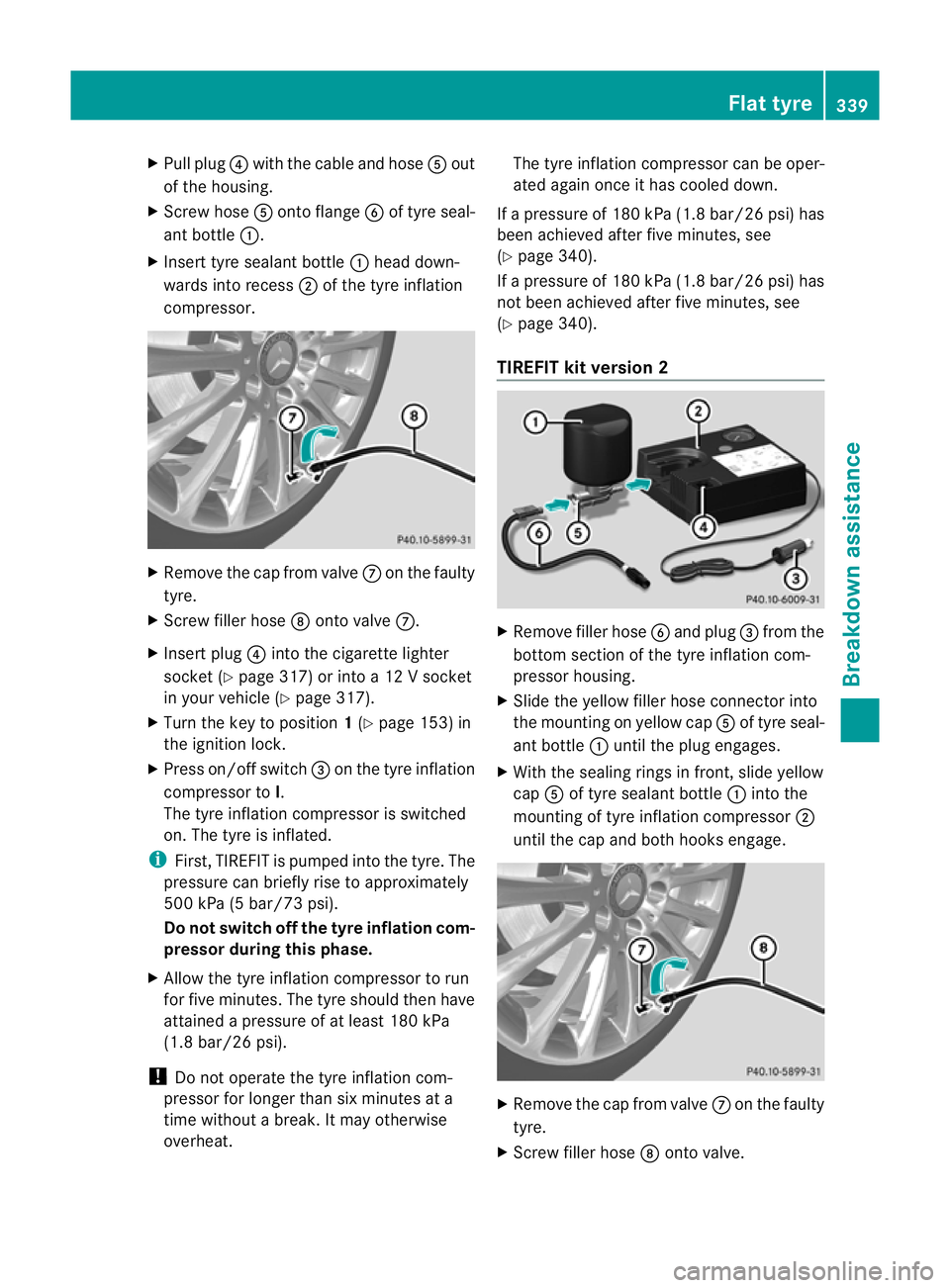
X
Pull plug ?with the cable and hose Aout
of the housing.
X Screw hose Aonto flange Bof tyre seal-
ant bottle :.
X Inser ttyre sealant bottle :head down-
wards into recess ;of the tyre inflation
compressor. X
Remove the cap from valve Con the faulty
tyre.
X Screw filler hose Donto valve C.
X Inser tplug ?into the cigarette lighter
socket (Y page 317) or into a 12 V socket
in your vehicle (Y page 317).
X Turn the key to position 1(Y page 153) in
the ignition lock.
X Press on/off switch =on the tyre inflation
compressor to I.
The tyre inflation compressor is switched
on. The tyre is inflated.
i First, TIREFIT is pumped into the tyre .The
pressure can briefly rise to approximately
500 kPa (5 bar/73 psi).
Do not switch off the tyre inflation com-
pressor during this phase.
X Allow the tyre inflation compressor to run
for five minutes. The tyre should then have
attained a pressure of at least 180 kPa
(1.8 bar/26 psi).
! Do not operate the tyre inflation com-
pressor for longer than six minutes at a
time without a break. It may otherwise
overheat. The tyre inflation compressor can be oper-
ated again once it has cooled down.
If a pressure of 180 kPa (1.8 bar/26 psi) has
been achieved after five minutes, see
(Y page 340).
If a pressure of 180 kPa (1.8 bar/26 psi) has
not been achieved after five minutes, see
(Y page 340).
TIREFIT kit version 2 X
Remove filler hose Band plug =from the
bottom section of the tyre inflation com-
pressor housing.
X Slide the yellow filler hose connector into
the mounting on yellow cap Aof tyre seal-
ant bottle :until the plug engages.
X With the sealing rings in front, slide yellow
cap Aof tyre sealant bottle :into the
mounting of tyre inflation compressor ;
until the cap and both hooks engage. X
Remove the cap from valve Con the faulty
tyre.
X Screw filler hose Donto valve. Flat tyre
339Breakdown assistance Z