2011 MERCEDES-BENZ C-CLASS ESTATE engine
[x] Cancel search: enginePage 354 of 401
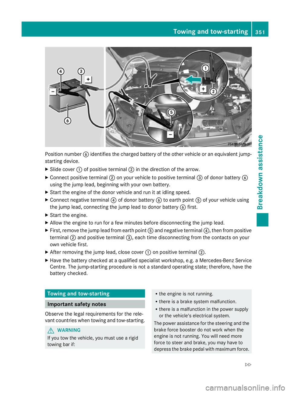
Position number
Bidentifies the charged battery of the other vehicle or an equivalent jump-
starting device.
X Slide cover :of positive terminal ;in the direction of the arrow.
X Connec tpositive terminal ;on your vehicle to positive terminal =of donor battery B
using the jump lead, beginning with your own battery.
X Start the engine of the donor vehicle and run it at idling speed.
X Connect negative terminal ?of donor battery Bto earth point Aof your vehicle using
the jump lead, connectingt he jump lead to donor battery Bfirst.
X Start the engine.
X Allow the engine to run for a few minutes before disconnecting the jump lead.
X First, remove the jump lead from earth point Aand negative terminal ?, then from positive
terminal ;and positive terminal =, each time disconnecting from the contacts on your
own vehicle first.
X After removing the jump lead, close cover :on positive terminal ;.
X Have the battery checked at a qualified specialist workshop, e.g. a Mercedes-Ben zService
Centre. The jump-starting procedure is not a standard operating state; therefore, have the
battery checked. Towing and tow-starting
Important safety notes
Observe the legal requirements for the rele-
vant countries when towing and tow-starting. G
WARNING
If you tow the vehicle, you must use a rigid
towing bar if: R
the engine is not running.
R there is a brake system malfunction.
R there is a malfunction in the power supply
or the vehicle's electrical system.
The power assistance for the steering and the
brake force booster do not work when the
engine is not running. You will need more
force to steer and brake, you may have to
depress the brake pedal with maximum force. Towing and tow-starting
351Breakdown assistance
Z
Page 356 of 401
X
Press the mark on cover :inwards in the
direction of the arrow.
X Take cover :off the opening.
X Screw the towing eye in clockwise to the
stop and tighten it.
Removing the towing eye X
Loosen the towing eye and unscrew it.
X Attach cover :to the bumper and press
until it engages.
X Place the towing eye in the vehicle tool kit. Towing the vehicle with the rear axle
raised
Only possible on vehicles without
4MATIC.
When towing your vehicle with the rear axle
raised, it is importan tthat you observe the
safety instructions (Y page 351).
! The ignition must be switched off if you
are towing the vehicle with the rear axle
raised. Intervention by ESP ®
could other-
wise damage the brake system.
X Switch on the hazard warning lamps
(Y page 121).
X Turn the key in the ignition lock to position
0 and remove the key from the ignition
lock.
X When leaving the vehicle, take the key or
the KEYLESS-GO key with you. Towing the vehicle with both axles on
the ground
It is important that you observe the safety
instructions when towing away your vehicle
(Y page 351). G
WARNING
The power assistance for the steering and the
brake force booster do not work when the
engine is not running. You will then need much more effort to brake and steer the vehi-
cle. Adapt your style of driving accordingly.
X Switch on the hazard warning lamps
(Y page 121).
i When towing with the hazard warning
lamps switched on, use the combination
switch as usual to signal achange of direc-
tion. In this case, only the turn signals for
the desired direction flash. When the com-
bination switch is reset, the hazard warning
lamps start flashing again.
X Turn the key to position 2in the ignition
lock.
X When the vehicle is stationary, depress the
brake pedal and keep it depressed.
X Vehicles with manual transmission:
depress the clutch pedal.
X Engage neutral.
or
X Vehicles with automatic transmission:
shift the automatic transmission to posi-
tion N.
X Release the brake pedal.
X Release the parking brake. Transporting the vehicle
The towing eyes or trailer tow hitch can be
used to pull the vehicle onto a trailer or trans-
porter if you wish to transport it.
X Vehicles with manual transmission:
shift to neutral.
X Vehicles with automatic transmission:
turn the key to position 2in the ignition
lock.
X Move the selector lever to N.
As soon as the vehicle is loaded:
X Prevent the vehicle from rolling away by
applying the parking brake.
X Vehicles with manual transmission:
shift to first gear or reverse gear. Towing and tow-starting
353Breakdown assistance Z
Page 357 of 401
X
Vehicles with automatic transmission:
move the selector lever to P.
X Turn the key in the ignition lock to position
0and remove the key from the ignition
lock.
X Secure the vehicle.
! Only lash the vehicle dow nby the wheels
or wheel rims, no tby parts of the vehicle
such as axle or steering components. Oth-
erwise, the vehicle could be damaged. Notes for 4MATIC vehicles
! Vehicles with 4MATIC mus tnot be towed
with the front or rear axle raised; otherwise,
the transmission may be damaged.
If the vehicle has transmission damage or
damage to the front or rear axle, have it trans-
ported on a transporter or trailer.
In the event of damage to the electrical
system
If the battery is defective, the automatic
transmission will be locked in position P. To
shift the automatic transmission to position
N, you must provide power to the vehicle's
electrical system in the same way as when
jump-starting (Y page 350).
Have the vehicle transported on a transporter
or trailer. Tow-starting (emergency engine
starting)
When tow-starting, it is important that you
observe the safety instructions (Y page 351)
and the legal requirements in each respective
country.
! Vehicles with automatic transmission
must not be tow-started. The transmission
may otherwise be damaged. Before tow-starting the following conditions
must be fulfilled:
R
the battery is connected.
R the engine has cooled down.
R the catalytic converters have cooled down.
X Switch on the hazard warning lamps
(Y page 121).
X Fit the towing eye (Y page 352).
X Secure the rigid towing bar or the towing
rope.
X Depress and hold the brake pedal.
X Turn the key to position 2in the ignition
lock.
X Depress the clutch pedal and keep it
depressed.
X Shift to neutral.
X Release the brake pedal.
X Tow-start the vehicle.
X Engage second gear.
X Release the clutch pedal slowly; do not
operate the accelerator pedal while doing
so.
The engine is started.
X Depress the clutch pedal and shift to neu-
tral.
X Stop at a suitable place.
X Apply the parking brake.
X Remove the rigid towing bar or towing rope.
X Remove the towing eye (Y page 353).
X Switch off the hazard warning lamps. Electrical fuses
Important safety notes
The fuses in your vehicle serve to close down
faulty circuits. If afuse blows, all the compo-
nents on the circuit and their functions stop
operating. G
WARNING
Only use fuses that have been approved for
Mercedes-Ben zvehicles and which have the
correct fuse rating for the systems con- 354
Electrical fusesBreakdown assistance
Page 358 of 401
cerned. Do not attempt to repair or bridge
faulty fuses. Otherwise, a circuit overload
could cause a fire .Have the cause traced and
rectified at a qualified specialist workshop,
e.g. a Mercedes-Benz Service Centre.
Blown fuses must be replaced with fuses of
the same rating, which you can recognise by
the colour and value. The fuse ratings are lis-
ted in the fuse allocatio nchart. AMercedes-
BenzS ervice Centre will be happy to advise
you.
If the newly inserted fuse also blows, have the
cause traced and rectified at a qualified spe-
cialist workshop, e.g. a Mercedes-Benz
Service Centre.
! Only use fuses that have been approved
for Mercedes-Benzv ehicles and which
have the correct fuse rating for the system
concerned. Otherwise, components or sys-
tems could be damaged. Before changing a fuse
X Park the vehicle and apply the parking
brake.
X Switch off all electrical consumers.
X Remove the key from the ignition lock.
The fuses are located in various fuse boxes:
R fuse box on the driver's side of the dash-
board
R fuse box in the engine compartment on the
left-hand side of the vehicle, when viewed
in the direction of travel
R fuse box in the boot/luggage compartment
on the right-hand side of the vehicle, when
viewed in the direction of travel
The fuse allocation chart is located in the
vehicle tool kit (Y page 335) in the stowage
compartment under the boot/luggage com-
partment floor. Dashboard fuse box
! Do not use a pointed objec tsuch as a
screwdriver to open the cover in the dash-
board. You could damage th edashboard or
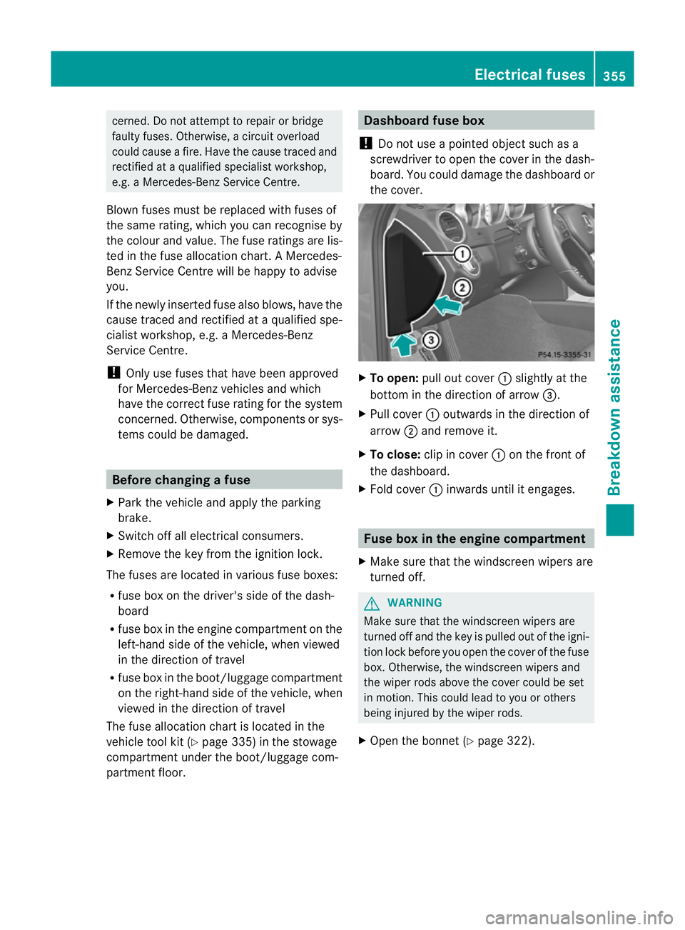
the cover. X
To open: pull out cover :slightly at the
bottom in the direction of arrow =.
X Pull cover :outwards in the direction of
arrow ;and remove it.
X To close: clip in cover :on the front of
the dashboard.
X Fold cover :inwards until it engages. Fuse box in the engine compartment
X Make sure that the windscree nwipers are
turned off. G
WARNING
Make sure that the windscreen wipers are
turned off and the key is pulled out of the igni-
tion lock before you open the cover of the fuse
box. Otherwise, the windscreen wipers and
the wiper rods above the cover could be set
in motion. This could lead to you or others
being injured by the wiper rods.
X Open the bonnet (Y page 322). Electrical fuses
355Breakdown assistance Z
Page 374 of 401
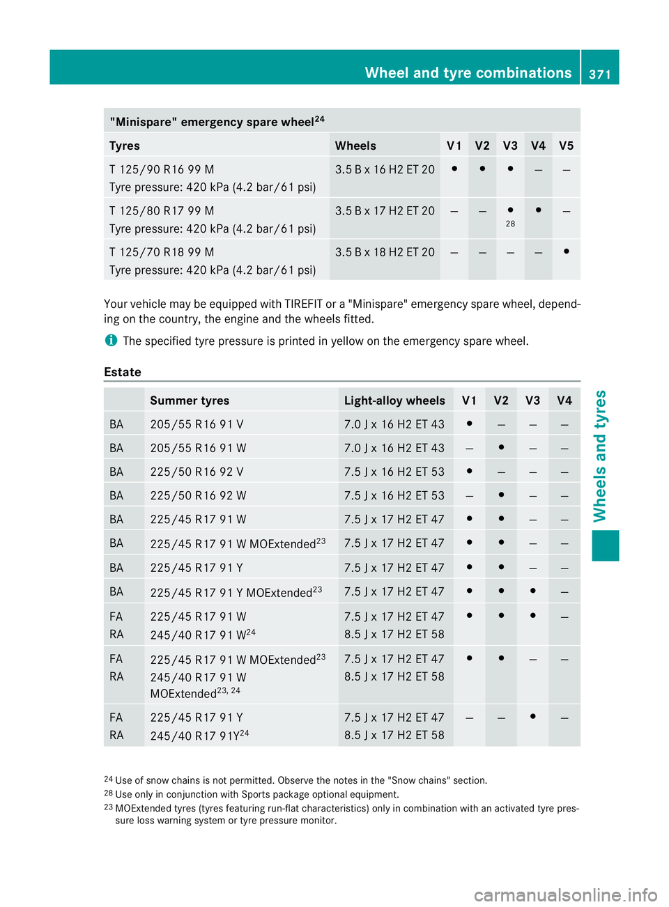
"Minispare" emergency spare wheel
24Tyres Wheels V1 V2 V3 V4 V5
T 125/90 R16 99 M
Tyre pressure: 420 kPa (4.2 bar/61 psi) 3.5 B x 16 H2 ET 20 # # #
— —
T 125/80 R17 99 M
Tyre pressure: 420 kPa (4.2 bar/61 psi) 3.5 B x 17 H2 ET 20 — — #
28 #
—
T 125/70 R18 99 M
Tyre pressure: 420 kPa (4.2 bar/61 psi) 3.5 B x 18 H2 ET 20 — — — — #
Your vehicle may be equipped with TIREFIT or a "Minispare" emergency spare wheel, depend-
ing on the country, the engine and the wheels fitted.
i The specified tyre pressure is printed in yellow on the emergency spare wheel.
Estate Summer tyres Light-alloy wheels V1 V2 V3 V4
BA 205/55 R16 91 V 7.0 J x 16 H2 ET 43 #
— — —
BA 205/55 R16 91 W 7.0 J x 16 H2 ET 43 — #
— —
BA 225/50 R16 92 V 7.5 J x 16 H2 ET 53 #
— — —
BA 225/50 R16 92 W 7.5 J x 16 H2 ET 53 — #
— —
BA 225/45 R17 91 W 7.5 J x 17 H2 ET 47 # #
— —
BA
225/45 R17 91 W MOExtended
23 7.5 J x 17 H2 ET 47 # #
— —
BA 225/45 R17 91 Y 7.5 J x 17 H2 ET 47 # #
— —
BA
225/45 R17 91 Y MOExtended
23 7.5 J x 17 H2 ET 47 # # #
—
FA
RA 225/45 R17 91 W
245/40 R17 91 W
24 7.5 J x 17 H2 ET 47
8.5 J x 17 H2 ET 58 # # #
—
FA
RA
225/45 R17 91 W MOExtended
23
245/40 R17 91 W
MOExtended 23, 24 7.5 J x 17 H2 ET 47
8.5 J x 17 H2 ET 58 # #
— —
FA
RA 225/45 R17 91 Y
245/40 R17 91Y
24 7.5 J x 17 H2 ET 47
8.5 J x 17 H2 ET 58 — — #
—
24
Use of snow chains is not permitted. Observe the notes in the "Snow chains" section.
28 Use only in conjunction with Sports package optional equipment.
23 MOExtended tyres (tyres featuring run-flat characteristics) only in combination with an activated tyre pres-
sure loss warning system or tyre pressure monitor. Wheel and tyre combinations
371Wheels and tyres Z
Page 376 of 401
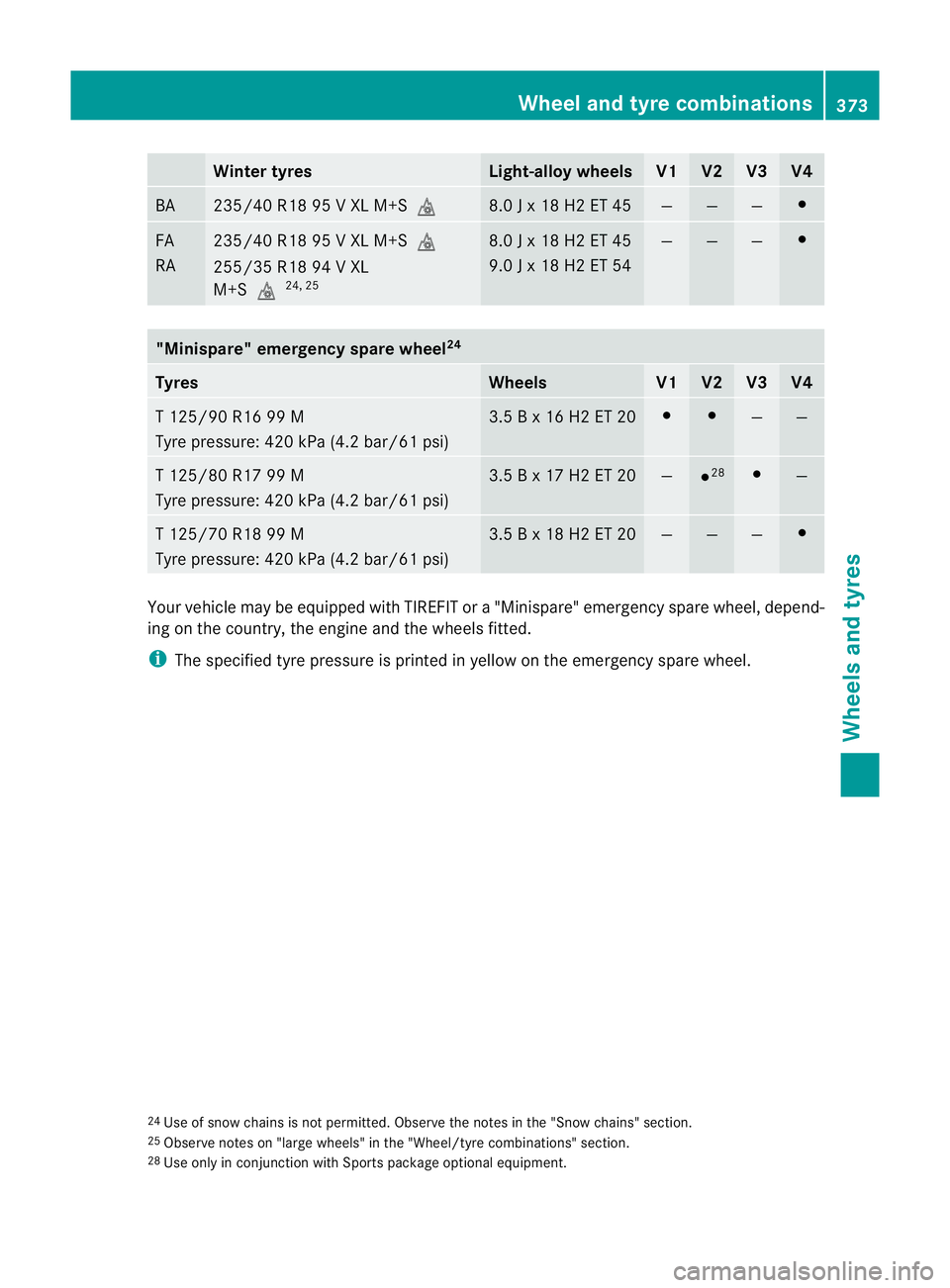
Winter tyres Light-alloy wheels V1 V2 V3 V4
BA 235/40 R18 95 V XL M+S
i 8.0 J x 18 H2 ET 45 — — — #
FA
RA 235/40 R18 95 V XL M+S
i
255/35 R18 94 V XL
M+Si 24, 25 8.0 J x 18 H2 ET 45
9.0 J x 18 H2 ET 54 — — — #
"Minispare" emergency spare wheel
24Tyres Wheels V1 V2 V3 V4
T 125/90 R16 99 M
Tyre pressure: 420 kPa (4.2 bar/61 psi) 3.5 B x 16 H2 ET 20 # #
— —
T 125/80 R17 99 M
Tyre pressure: 420 kPa (4.2 bar/61 psi) 3.5 B x 17 H2 ET 20 —
#
28 #
—
T 125/70 R18 99 M
Tyre pressure: 420 kPa (4.2 bar/61 psi) 3.5 B x 18 H2 ET 20 — — — #
Yourv
ehicle may be equipped with TIREFIT or a "Minispare" emergency spare wheel, depend-
ing on the country, the engine and the wheels fitted.
i The specified tyre pressure is printed in yellow on the emergency spare wheel.
24 Use of snow chains is not permitted. Observe the notes in the "Snow chains" section.
25 Observe notes on "large wheels" in the "Wheel/tyre combinations" section.
28 Use only in conjunction with Sports package optional equipment. Wheel and tyre combinations
373Wheels and tyres Z
Page 380 of 401
H
Environmental note
Daimler AG also supplies reconditioned
assemblies and parts which are of the same
quality as new parts. For these, the same war-
ranty applies as for new parts.
Always specify the vehicle identification num-
ber (VIN) (Y page 379) and the engine num-
ber (Y page 379) when ordering genuine
Mercedes-Ben zparts. Vehicle electronics
Tampering with the engine electron-
ics
G
WARNING
Only have work on the engine electronics and
related components carried out at a qualified
specialist workshop which has the necessary
specialist knowledge and tools to carry out
the work required. Mercedes-Benz recom-
mends that you use a Mercedes-Ben zService
Centre for this purpose. In particular, work
relevant to safety or on safety-related sys-
tems must be carried out at a qualified spe-
cialist workshop. Otherwise, the vehicle's
roadworthiness could be affected.
! Only have maintenance work on the
engine electronics and its associated parts,
such as control units, sensors and connec-
tor leads, carried out at a qualified special-
ist workshop, e.g. a Mercedes-Benz Service
Centre. Vehicle componentsm ay other-
wise wear more quickly and the vehicle's
operating permit may be invalidated. Retrofitting of two-way radios and
mobile phones (RF transmitters)
Use the Technical Specification
ISO/TS 21609 30
implementation regulation
when retrofitting RF (radio frequency) trans-
mitters. If your vehicle has fittings for two-way radio
equipment, use the power supply or aerial
connections intended for use with the basic
wiring. Be sure to observe the manufacturer's
additional instructions when installing the fit-
tings.
!
Have aftermarket radio frequency trans-
mitting equipmen tinstalled at a qualified
specialist workshop .Mercedes-Benzr ec-
ommends that you use a Mercedes-Benz
Service Centre for this purpose.
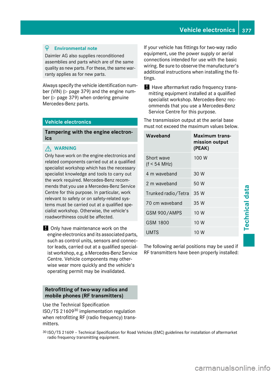
The transmission output at the aerial base
must not exceed the maximum values below. Waveband Maximum trans-
mission output
(PEAK)
Short wave
(f < 54 MHz) 100 W
4 m waveband 30 W
2 m waveband 50 W
Trunked radio/Tetra 35 W
70 cm waveband 35 W
GSM 900/AMPS 10 W
GSM 1800 10 W
UMTS 10 W
The following aerial positions may be used if
RF transmitters have been properly installed:
30 ISO/TS 2160 9–Technical Specification for Road Vehicles (EMC) guidelines for installation of aftermarket
radio frequency transmitting equipment. Vehicle electronics
377Technical data Z
Page 382 of 401
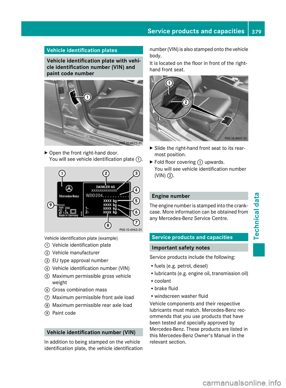
Vehicle identification plates
Vehicle identification plate with vehi-
cle identification number (VIN) and
pain tcode number X
Open the fron tright-hand door.
You will see vehicle identification plate :.Vehicle identification plate (example)
:
Vehicle identification plate
; Vehicle manufacturer
= EU type approval number
? Vehicle identification number (VIN)
A Maximum permissible gross vehicle
weight
B Gross combination mass
C Maximum permissible front axle load
D Maximum permissible rear axle load
E Paint code Vehicle identification number (VIN)
In additio nto being stamped on the vehicle
identification plate, the vehicle identification number (VIN) is also stamped onto the vehicle
body.
It is located on the floor in front of the right-
hand front seat.
X
Slide the right-hand front seat to its rear-
most position.
X Fold floor covering :upwards.
You will see vehicle identification number
(VIN) ;. Engine number
The engine number is stamped into the crank-
case. More information can be obtained from
any Mercedes-Benz Service Centre. Service products and capacities
Important safety notes
Service products include the following:
R fuels (e.g. petrol, diesel)
R lubricants (e.g. engine oil, transmission oil)
R coolant
R brake fluid
R windscreen washer fluid
Vehicle components and their respective
lubricants must match. Mercedes-Benz rec-
ommends that you use products that have
been tested and specially approved by
Mercedes-Benz. These products are listed in
this Mercedes-Benz Owner's Manual in the
relevant section. Service products and capacities
379Technical data Z