Page 299 of 356
719
Maintenance
POWER STEERING FLUID (IF EQUIPPED)
G090100AHM
Checking the power steering fluid
level
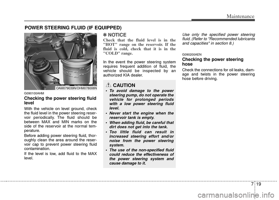
With the vehicle on level ground, check
the fluid level in the power steering reser-
voir periodically. The fluid should be
between MAX and MIN marks on the
side of the reservoir at the normal tem-
perature.
Before adding power steering fluid, thor-
oughly clean the area around the reser-
voir cap to prevent power steering fluid
contamination.
If the level is low, add fluid to the MAX
level.
✽ ✽NOTICE
Check that the fluid level is in the
"HOT" range on the reservoir. If the
fluid is cold, check that it is in the
"COLD" range.
In the event the power steering system
requires frequent addition of fluid, the
vehicle should be inspected by an
authorized KIA dealer.
Use only the specified power steering
fluid. (Refer to "Recommended lubricants and capacities" in section 8.)
G090200AEN
Checking the power steering
hose
Check the connections for oil leaks, dam-
age and twists in the power steering
hose before driving.
CAUTION
To avoid damage to the power steering pump, do not operate thevehicle for prolonged periodswith a low power steering fluidlevel.
Never start the engine when the reservoir tank is empty.
When adding fluid, be careful that dirt does not get into the tank.
Too little fluid can result in increased steering effort and/ornoise from the power steeringsystem.
The use of the non-specified fluid could reduce the effectiveness ofthe power steering system and cause damage to it.OAM079039N/OHM078006N
Page 301 of 356
721
Maintenance
✽
✽NOTICE
New automatic transaxle fluid should be
red. The red dye is added so the assem-
bly plant can identify it as automatic
transaxle fluid and distinguish it from
engine oil or antifreeze. The red dye,
which is not an indicator of fluid quali-
ty, is not permanent. As the vehicle is
driven, the automatic transaxle fluid
will begin to look darker. The color may
eventually appear light brown.
Therefore, have an authorized KIA
dealer change the automatic transaxle
fluid according to the Scheduled
Maintenance at the beginning of this
section.
Use only the specified automatic
transaxle fluid. (Refer to "Recommended
lubricants or capacities" in section 8.)
G100200AUN-U1
Changing the automatic transaxle
fluid
Have the automatic transaxle fluid
changed by an authorized KIA dealer
according to the Maintenance Schedule
at the beginning of this section.
Page 308 of 356
Maintenance
28
7
G190200AUN
Battery recharging
Your vehicle has a maintenance-free,
calcium-based battery.
If the battery becomes discharged in a
short time (because, for example, the
headlights or interior lights were left on
while the vehicle was not in use),
recharge it by slow charging (trickle)
for 10 hours.
If the battery gradually discharges because of high electric load while the
vehicle is being used, recharge it at 20-
30A for two hours.
(Continued)
When lifting a plastic-cased bat-tery, excessive pressure on the
case may cause battery acid to
leak, resulting in personal injury.
Lift with a battery carrier or with
your hands on opposite corners.
Never attempt to recharge the battery when the battery cables
are connected.
The electrical ignition system works with high voltage. Never
touch these components with the
engine running or the ignition
switched on.
Failure to follow the above warn-
ings can result in serious bodily
injury or death.WARNING- Recharging battery
When recharging the battery,
observe the following precautions:
The battery must be removed
from the vehicle and placed in an
area with good ventilation.
Do not allow cigarettes, sparks, or flame near the battery.
Watch the battery during charg- ing, and stop or reduce the charg-
ing rate if the battery cells begin
gassing (boiling) violently or if
the temperature of the electrolyte
of any cell exceeds 49°C (120°F).
Wear eye protection when check- ing the battery during charging.
Disconnect the battery charger in the following order.
1. Turn off the battery charger main switch.
2. Unhook the negative clamp from the negative battery terminal.
3. Unhook the positive clamp from the positive battery terminal.
Page 320 of 356
Maintenance
40
7
G201100AAM-EC
Tire terminology and definitions
Air Pressure: The amount of air
inside the tire pressing outward on
the tire. Air pressure is expressed in
kilopascal (kPa) or pounds per
square inch (psi).
Accessory Weight : This means the
combined weight of optional acces-
sories. Some examples of optional
accessories are, automatic
transaxle, power seats, and air con-
ditioning.
Aspect Ratio : The relationship of a
tire's height to its width.
Belt: A rubber coated layer of cords
that is located between the plies and
the tread. Cords may be made from
steel or other reinforcing materials.
Bead: The tire bead contains steel
wires wrapped by steel cords that
hold the tire onto the rim.
Bias Ply Tire : A pneumatic tire in
which the plies are laid at alternate
angles less than 90 degrees to the
centerline of the tread. Cold Tire Pressure: The amount of
air pressure in a tire, measured in
kilopascals (kPa) or pounds per
square inch (psi) before a tire has
built up heat from driving.
Curb Weight: This means the weight
of a motor vehicle with standard and
optional equipment including the
maximum capacity of fuel, oil and
coolant, but without passengers and
cargo.
DOT Markings: The DOT code
includes the Tire Identification
Number (TIN), an alphanumeric des-
ignator which can also identify the
tire manufacturer, production plant,
brand and date of production.
GVWR: Gross Vehicle Weight Rating
GAWR FRT: Gross Axle Weight
Rating for the Front Axle.
GAWR RR: Gross Axle Weight
Rating for the Rear axle.
Intended Outboard Sidewall
: The
side of an asymmetrical tire, that
must always face outward when
mounted on a vehicle. Kilopascal (kPa): The metric unit for
air pressure.
Load Index: An assigned number
ranging from 1 to 279 that corre-
sponds to the load carrying capacity
of a tire.
Maximum Inflation Pressure
: The
maximum air pressure to which a
cold tire may be inflated. The maxi-
mum air pressure is molded onto the
sidewall.
Maximum Load Rating : The load
rating for a tire at the maximum per-
missible inflation pressure for that
tire.
Maximum Loaded Vehicle Weight:
The sum of curb weight; accessory
weight; vehicle capacity weight; and
production options weight.
Normal Occupant Weight: The
number of occupants a vehicle is
designed to seat multiplied by 68 kg
(150 pounds).
Occupant Distribution : Designated
seating positions.
Page 323 of 356
743
Maintenance
FUSES
G210000AAM
A vehicle’s electrical system is protected
from electrical overload damage by
fuses.This vehicle has 2 fuse panels, one locat-
ed in the driver’s side panel bolster, the
other in the engine compartment near
the battery.
If any of your vehicle’s lights, acces-
sories, or controls do not work, check the
appropriate circuit fuse. If a fuse has
blown, the element inside the fuse will
melt.
If the electrical system does not work,
first check the driver’s side fuse panel.
Always replace a blown fuse with one of
the same rating.
If the replacement fuse blows, this indi-
cates an electrical problem. Avoid using
the system involved and immediately
consult an authorized KIA dealer.
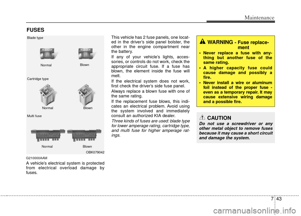
Three kinds of fuses are used: blade type
for lower amperage rating, cartridge type, and multi fuse for higher amperage rat-ings.
WARNING - Fuse replace- ment
Never replace a fuse with any-
thing but another fuse of the
same rating.
A higher capacity fuse could cause damage and possibly a
fire.
Never install a wire or aluminum foil instead of the proper fuse -
even as a temporary repair. It may
cause extensive wiring damage
and a possible fire.
CAUTION
Do not use a screwdriver or anyother metal object to remove fusesbecause it may cause a short circuitand damage the system.
OBK079042
Normal
Normal
Blade type
Cartridge type
Multi fuse Blown
Blown
Normal Blown
Page 329 of 356
749
Maintenance
Description Fuse ratingProtected component
ABS10AABS Control Module, ESC Control Module, ESC Switch, Steering Angle Sensor,
E/R Fuse & Relay Box (Multipurpose Check Connector)
IGN 1 10A Tire Pressure Monitoring Module, Multifunction Switch (Remocon), Audio
AUDIO 15A Audio
MEMORY 10A BCM, Instrument Cluster (IND.), A/C Control Module, Tire Pressure Monitoring Module,
Door Warning Switch, Overhead Console Assembly (Map Lamp), Center Room Lamp, Luggage Lamp
P/OUTLET. RR 15A Rear Power Outlet A/BAG 15A SRS Control Module, Weight Classification Module
IGN COIL 15A Condenser, Ignition Coil #1 ~ #4
T/SIG 10A Hazard Switch
CLUSTER 10A BCM, Instrument Cluster (IND.), A/C Control Module
ECU 10A ECM, PCM
START 10A E/R Fuse & Relay Box (Start Relay)
B/UP LP 10A Back-up Lamp Switch (M/T), Transaxle Range Switch (A/T), Cruise Control Module
A/BAG W/LP 10A Instrument Cluster (Air Bag IND.)
POWER
CONNECTOR
Page 330 of 356
Maintenance
50
7
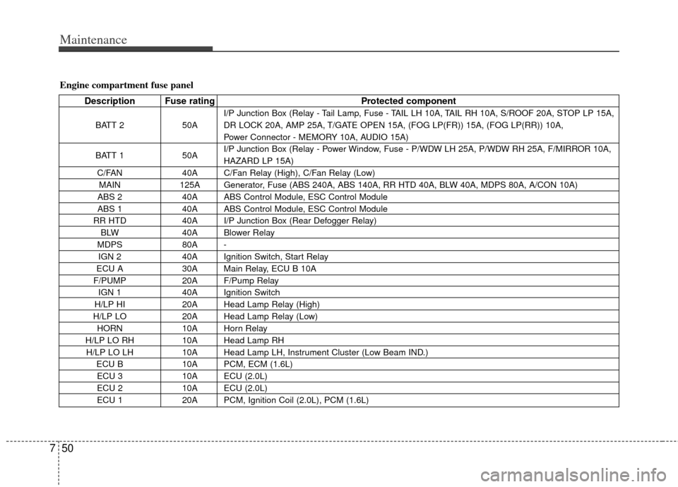
Engine compartment fuse panel
Description Fuse rating Protected component
BATT 250AI/P Junction Box (Relay - Tail Lamp, Fuse - TAIL LH 10A, TAIL RH 10A, S/ROOF 20A, STOP LP 15A,
DR LOCK 20A, AMP 25A, T/GATE OPEN 15A, (FOG LP(FR)) 15A, (FOG LP(RR)) 10A,
Power Connector - MEMORY 10A, AUDIO 15A)
BATT 1 50AI/P Junction Box (Relay - Power Window, Fuse - P/WDW LH 25A, P/WDW RH 25A, F/MIRROR 10A,
HAZARD LP 15A)
C/FAN 40A C/Fan Relay (High), C/Fan Relay (Low)
MAIN 125A Generator, Fuse (ABS 240A, ABS 140A, RR HTD 40A, BLW 40A, MDPS 80A, A/CON 10A)
ABS 2 40A ABS Control Module, ESC Control Module
ABS 1 40A ABS Control Module, ESC Control Module
RR HTD 40A I/P Junction Box (Rear Defogger Relay)
BLW 40A Blower Relay
MDPS 80A -
IGN 2 40A Ignition Switch, Start Relay
ECU A 30A Main Relay, ECU B 10A
F/PUMP 20A F/Pump Relay
IGN 1 40A Ignition Switch
H/LP HI 20A Head Lamp Relay (High)
H/LP LO 20A Head Lamp Relay (Low)
HORN 10A Horn Relay
H/LP LO RH 10A Head Lamp RH
H/LP LO LH 10A Head Lamp LH, Instrument Cluster (Low Beam IND.)
ECU B 10A PCM, ECM (1.6L)
ECU 3 10A ECU (2.0L)
ECU 2 10A ECU (2.0L)
ECU 1 20A PCM, Ignition Coil (2.0L), PCM (1.6L)
Page 331 of 356
751
Maintenance
Description Fuse ratingProtected component
INJECTOR15A Immobilizer Module, Idle Speed Control Actuator, Injetor #1~4, Canister Close Valve
SENSOR 10ACamshaft Position Sensor, Oil Control Valve, Oxygen Sensor (Up/Down), Canister Purje Solenoid Valve,
Stop Lamp Switch, A/Con Relay, C/Fan Relay (High/Low), Crankshaft Position Sensor (2.0L),
Camshaft Position Sensor (1.6L)
A/CON 10A A/Con Relay