2011 KIA Sorento sensor
[x] Cancel search: sensorPage 139 of 377

461
Features of your vehicle
Rear parking assist system pre-
cautions The rear parking assist system maynot sound consistently depending on
the speed and shapes of the objects
detected.
The rear parking assist system may malfunction if the vehicle bumper
height or sensor installation has been
modified or damaged. Any non-factory
installed equipment or accessories
may also interfere with the sensor per-
formance.
The sensor may not recognize objects less than 40 cm (15 in.) from the sen-
sor, or it may sense an incorrect dis-
tance. Use caution.
When the sensor is frozen or stained with snow, dirt, or water, the sensor
may be inoperative until the stains are
removed using a soft cloth.
Do not push, scratch or strike the sen- sor. Sensor damage could occur.
✽ ✽ NOTICEThis system can only sense objects with-
in the range and location of the sensors;
It can not detect objects in other areas
where sensors are not installed. Also,
small or slim objects, such as poles or
objects located between sensors may not
be detected by the sensors.
Always visually check behind the vehi-
cle when backing up.
Be sure to inform any drivers of the
vehicle that may be unfamiliar with the
system regarding the systems capabili-
ties and limitations.
Self-diagnosisIf you don’t hear an audible warning
sound or if the buzzer sounds intermit-
tently when shifting the gear to the R
(Reverse) position, this may indicate a
malfunction in the rear parking assist sys-
tem. If this occurs, have your vehicle
checked by an authorized KIA dealer as
soon as possible.
WARNING
Pay close attention when the vehi-
cle is driven close to objects on the
road, particularly pedestrians, and
especially children. Be aware that
some objects may not be detected
by the sensors, due to the object’s
distance, size or material, all of
which can limit the effectiveness of
the sensor. Always perform a visu-
al inspection to make sure the vehi-
cle is clear of all obstructions
before moving the vehicle in any
direction.
WARNING
Your new vehicle warranty does not
cover any accidents or damage to
the vehicle or injuries to its occu-
pants due to a rear parking assist
system malfunction. Always drive
safely and cautiously.
XM CAN (ENG) 4(~101).QXP 4/14/2010 10:42 AM Page 61
Page 143 of 377

465
Features of your vehicle
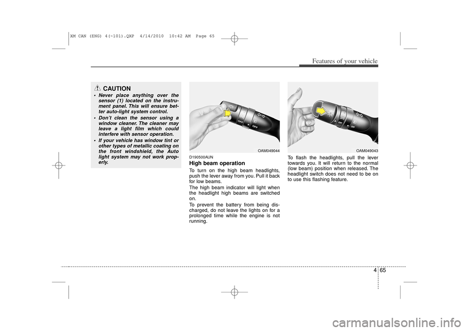
D190500AUNHigh beam operation To turn on the high beam headlights,
push the lever away from you. Pull it back
for low beams.
The high beam indicator will light when
the headlight high beams are switched
on.
To prevent the battery from being dis-
charged, do not leave the lights on for a
prolonged time while the engine is not
running.To flash the headlights, pull the lever
towards you. It will return to the normal
(low beam) position when released. The
headlight switch does not need to be on
to use this flashing feature.
CAUTION
Never place anything over the
sensor (1) located on the instru-ment panel. This will ensure bet-ter auto-light system control.
Don’t clean the sensor using a window cleaner. The cleaner mayleave a light film which could interfere with sensor operation.
If your vehicle has window tint or other types of metallic coating onthe front windshield, the Autolight system may not work prop- erly.
OAM049044
OAM049043
XM CAN (ENG) 4(~101).QXP 4/14/2010 10:42 AM Page 65
Page 162 of 377

Features of your vehicle84
4Automatic heating and air condi-
tioningThe automatic climate control system is
controlled by simply setting the desired
temperature.
The Full Automatic Temperature Control
(FATC) system automatically controls the
heating and cooling system as follows;
1. Press the AUTO button. The modes,
fan speeds, air intake and air-condi-
tioning will be controlled automatically
by setting the temperature. 2. Set the temperature switch to the
desired temperature.
If the temperature is set to the lowest
setting (Lo), the air conditioning sys-
tem will operate continuously.
3. To turn the automatic operation off, select any button or switch of the fol-
lowing:
Mode selection button
Air conditioning button
Front windshield defroster button
Air intake control button
Fan speed control switch
The selected function will be controlled manually while other functions operate
automatically.
For your convenience and to improve the
effectiveness of the climate control, use
the AUTO button and set the temperature
to 23°C/73°F.
✽ ✽ NOTICENever place anything over the sensor
located on the instrument panel to
ensure better control of the heating and
cooling system.
OXM049153
OXM049152
XM CAN (ENG) 4(~101).QXP 4/14/2010 10:46 AM Page 84
Page 294 of 377

What to do in an emergency16
6TOWINGF080100AAM-EUTowing serviceIf emergency towing is necessary, we
recommend having it done by an author-
ized KIA dealer or a commercial tow-
truck service. Proper lifting and towing
procedures are necessary to prevent
damage to the vehicle. The use of wheel
dollies or flatbed is recommended.For trailer towing guidelines information,
refer to “Trailer towing” in section 5.
On 4WD vehicles, your vehicle must be
towed with a wheel lift and dollies or
flatbed equipment with all the wheels off
the ground.
On 2WD vehicles, it is acceptable to tow
the vehicle with the rear wheels on the
ground (without dollies) and the front
wheels off the ground.
If any of the loaded wheels or suspen-
sion components are damaged or the
vehicle is being towed with the front
wheels on the ground, use a towing dolly
under the front wheels.
When being towed by a commercial tow
truck and wheel dollies are not used, the
front of the vehicle should always be lift-
ed, not the rear.
OXM069028 dollydolly
CAUTION
The 4WD vehicle should never be
towed with the wheels on theground. This can cause seriousdamage to the transaxle or the 4WDsystem.
WARNING
If your vehicle is equipped with side
and curtain air bag, set the ignition
switch to LOCK or ACC position
when the vehicle is being towed.
The side and curtain air bag may
deploy when the ignitions is ON,
and the rollover sensor detects the
situation as a rollover.
XM CAN (ENG) 6.QXP 11/26/2009 12:06 PM Page 16
Page 319 of 377

Maintenance22
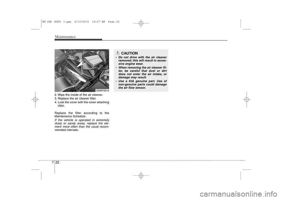
72. Wipe the inside of the air cleaner.
3. Replace the air cleaner filter.
4. Lock the cover with the cover attaching
clips.
Replace the filter according to the
Maintenance Schedule.If the vehicle is operated in extremely dusty or sandy areas, replace the ele-ment more often than the usual recom-mended intervals.
OXM079014
CAUTION
Do not drive with the air cleaner removed; this will result in exces-sive engine wear.
When removing the air cleaner fil- ter, be careful that dust or dirtdoes not enter the air intake, ordamage may result.
Use a KIA genuine part. Use of non-genuine parts could damagethe air flow sensor.
XM CAN (ENG) 7.qxp 4/14/2010 10:57 AM Page 22
Page 347 of 377

Maintenance50
7Inner fuse panel
Description Fuse rating Protected component
MODULE 2 10AInstrument Cluster (IND./MICOM), Tire Pressure Monitoring Module, Audio, Multifunction Switch (Remocon),
Rear Parking Assist Buzzer ICM Relay Box (DBC Relay), ESC Off Switch, DBC Switch, Steering Angle
Sensor, Alternator, Smart Key Control Module A/V & Navigation Head Unit, Rear Monitor, IPM (BCM IG1)
MODULE 1 10ASmart Key Control Module, Rear Parking Assist Control Module E/R Fuse & Relay Box (Fuse - B/UP LP,
ABS, ECU 2), PDM, 4WD ECM
RPAS 7.5A Rear Parking Assist Switch
A/BAG IND 10A Instrument Cluster (IND.), PODS Module, Digital Clock
A/BAG 15A SRS Control Module
START 7.5A E/R Fuse & Relay Box (Relay - Start, Sub Start, Burglar Alarm), PDM
WIPER RR 15AICM Relay Box (Rear Wiper Relay), Rear Wiper Motor
Rear Wiper Switch, Rear Washer Switch
WIPER FRT 25A E/R Fuse & Relay Box (Wiper (Low) Relay), Front Wiper Motor, Multifunction Switch (Wiper)
AUDIO 2 7.5AAMP, Power Outside Mirror Switch, Smart Key Control Module, PDM, Audio, A/V & Navigation Head
Unit, Digital Clock, IPM (BCM ACC), DVD Player Can, Rear Monitor
P/OUTLET RR 15A Rear Power Outlet
P/OUTLET FRT 25A Driver/Passenger Power Outlet
MODULE 3 7.5A Not Used
A/CON 7.5AFront A/C Control Module, Active Incar Sensor, Cluster Ionize, PDM, ICM Relay Box (Front Seat Warmer
Relay, Rear A/C Relay) E/R Fuse & Relay Box (Blower Relay), Sunroof Motor, Electro Chromic Mirror,
IPM (BCM IG2)
AMP 30A AMP
DRL 7.5A Ground (GE01)
A/CON MANU 7.5A PCM, Front Blower Resistor, Front A/C Control Module
A/CON AUTO 7.5A Front A/C Control Module
XM CAN (ENG) 7.qxp 4/14/2010 10:59 AM Page 50
Page 349 of 377

Maintenance52
7Engine compartment fuse panel
Description Fuse rating Protected component
ALT175A Alternator
MULTI FUSE I/P B+2
60A IPM (Fuse - S/HTR FRT, P/SEAT, Power Connector - MODULE, ROOM LP DOOR LP)
BLOWER 40A Blower Relay
RR HTD 40A Rear Defogger Relay
ABS 1 40A ESC Control Module, Multipurpose Check Connector
ABS 2 40A ESC Control Module, Multipurpo se Check Connector
I/P B+3 60A IPM (Fuse - HAZARD, TPMS, F/LID)
I/P B+1 60A IPM (Fuse - DR LOCK, SUNROOF, 4WD, PDM, SMART KEY)
FUSE IGN 2
40A Start Relay, W/O Smart Key - Ignition Switch, With Smart Key - PDM Relay Box (IGN2 Relay)
TRAILER 30A Trailer Power Outlet
IGN 1 30A W/O Smart Key - Ignition Switch, With Smart Key - PDM Relay Box (IGN1 Relay)
HORN 15A Horn Relay
STOP LP 15A Stop Lamp Switch, ICM Relay Box (DBC Relay)
B+ SENSOR 15A Battery Sensor
DEICER 15A Front Wiper Deicer Relay
C/FAN 50A Cooling Fan Relay Low/High
I/P B+4 50A IPM (Fuse - P/WDW LH, P/WDW RH, B/A HORN, A/CON REAR, AMP)
ECU 2 7.5A Sub Start Relay, PCM, Transaxle Range Switch, Alternator (G6DC)
ABS 7.5A ESC Control Module, Multipurpose Check Connector, Stop Lamp Switch (G4KE)
B/UP LP 7.5A Back-Up Lamp Relay (A/T), Back-Up Lamp Switch (M/T)
XM CAN (ENG) 7.qxp 4/14/2010 11:00 AM Page 52
Page 350 of 377

753
Maintenance
Description Fuse ratingProtected component
EMS
BOX ECU 30A Engine Control Relay
ECU 3
20AG4KE - Ignition Coil #1/2/3/4, Condenser
G6DC - Ignition Coil #1/2/3/4/5/6, Condenser #1/2
SENSOR 1 10AG4KE - Variable Intake Manifold Valve, Crankshaft Position Sensor, Immobilizer Module, Camshaft
Position Sensor #1/2, Oil Control Valve #1/2, Canister Purge Control Solenoid Valve,
Canister Close Valve, Cooling Fan (Low) Relay
G6DC - Variable Intake Manifold Valve #1/2, Immobilizer Module, Canister Purge Control Solenoid Valve, Oil Control Valve #1/2 (Exhaust), Oil Control Valve #1/2 (Intake), Canister Close
Valve
SENSOR 2 10A G6DC - Cooling Fan (Low) Relay, Stop Lamp Switch
SENSOR 3 10AG4KE - Injector #1/2/3/4, A/C Relay
G6DC - PCM, Injector #1/2/3/4/5/6, A/C Relay
SENSOR 4 15AG4KE - Oxygen Sensor Up/Down, Fuel Pump Relay
G6DC - PCM, Oxygen Sensor #1/2/3/4, Fuel Pump Relay, Variable Charge Motion Actuator
ECU 1 15A PCM
A/CON 10A A/C Relay
F/PUMP 15A Fuel Pump Relay
XM CAN (ENG) 7.qxp 4/14/2010 11:00 AM Page 53