Page 125 of 370

Features of your vehicle
108
3
Inside rearview mirror
Adjust the rearview mirror to center on
the view through the rear window. Make
this adjustment before you start driving.
Day/night rearview mirror
Make this adjustment before you start
driving and while the day/night lever is in
the day position.
Pull the day/night lever toward you to
reduce glare from the headlights of vehi-
cles behind you during night driving.
Remember that you lose some rearview
clarity in the night position. Electric chromic mirror (ECM)
(if equipped)
The electric rearview mirror automatical-
ly controls the glare from the headlights
of the car behind you in nighttime or low
light driving conditions. The sensor
mounted in the mirror senses the light
level around the vehicle, and through a
chemical reaction, automatically controls
the headlight glare from vehicles behind
you.
When the engine is running, the glare is
automatically controlled by the sensor
mounted in the rearview mirror.
Whenever the shift lever is shifted into
reverse (R), the mirror will automatically
go to the brightest setting in order to
improve the drivers view behind the vehi-
cle.
WARNING - Rear visibility
Do not place objects in the rear seat
or cargo area which would interfere
with your vision out the rear win-
dow.
CAUTION
When cleaning the mirror, use apaper towel or similar materialdampened with glass cleaner. Do not spray glass cleaner directly onthe mirror as that may cause the liq- uid cleaner to enter the mirror hous-ing.
OVQ028105
Day
Night
Day/Night lever
WARNING
Do not adjust the rearview mirror
while the vehicle is moving. This
could result in loss of control, and
an accident which could cause
death, serious injury or property
damage.
WARNING
Do not modify the inside mirror and
do not install a wide mirror. It could
result in injury, during an accident
or deployment of the air bag.
Page 134 of 370

3117
Features of your vehicle
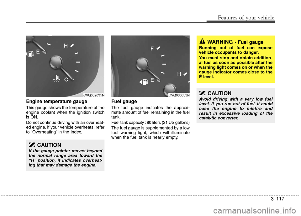
Engine temperature gauge
This gauge shows the temperature of the
engine coolant when the ignition switch
is ON.
Do not continue driving with an overheat-
ed engine. If your vehicle overheats, refer
to “Overheating” in the Index.
Fuel gauge
The fuel gauge indicates the approxi-
mate amount of fuel remaining in the fuel
tank.
Fuel tank capacity : 80 liters (21 US gallons)
The fuel gauge is supplemented by a low
fuel warning light, which will illuminate
when the fuel tank is nearly empty.
OVQ036033N
WARNING- Fuel gauge
Running out of fuel can expose
vehicle occupants to danger.
You must stop and obtain addition-
al fuel as soon as possible after the
warning light comes on or when the
gauge indicator comes close to the
E level.
CAUTION
Avoid driving with a very low fuellevel. If you run out of fuel, it couldcase the engine to misfire and result in excessive loading of thecatalytic converter.
CAUTION
If the gauge pointer moves beyond the normal range area toward the“H” position, it indicates overheat- ing that may damage the engine.
OVQ039031N
Page 144 of 370

3127
Features of your vehicle
Engine oil pressure
warning
This warning light indicates the engine oil
pressure is low.
If the warning light illuminates while dri-
ving:
1. Drive safely to the side of the road andstop.
2. With the engine off, check the engine oil level. If the level is low, add oil as
required.
If the warning light remains on after
adding oil or if oil is not available, call an
Authorized Kia Dealer.
Parking brake & brake
fluid warning
Parking brake warning
This light is illuminated when the parking
brake is applied with the ignition switch in
the START or ON position. The warning
light should go off when the parking
brake is released while engine is run-
ning.
Low brake fluid level warning
If the warning light remains on, it may
indicate that the brake fluid level in the
reservoir is low.
If the warning light remains on:
1. Drive carefully to the nearest safe location and stop your vehicle.
2. With the engine stopped, check the brake fluid level immediately and add
fluid as required. Then check all brake
components for fluid leaks.
3. Do not drive the vehicle if leaks are found, the warning light remains on or
the brakes do not operate properly.
Have it towed to any Authorized Kia
Dealer for a brake system inspection
and necessary repairs. To check bulb operation, check whether
the parking brake and brake fluid warning
light illuminates when the ignition switch
is in the ON position.
Parking start warning chime
If you drive over 10 km/h (6 mph) with the
parking brake applied, the parking start
warning chime will sound.
Front fog light indicator
(if equipped)
This light comes on when the front fog
lights are ON.
Shift pattern indicators
(if equipped)
The individual indicators illuminate to
show the automatic transaxle shift lever
selection.
CAUTION
If the engine is not stopped imme-
diately after the engine oil pressurewarning light is illuminated, severedamage could result.
WARNING
Driving the vehicle with a warning
light on is dangerous. If the brake
warning light remains on, have the
brakes checked and repaired imme-
diately by an authorized Kia Dealer.
Page 153 of 370
Features of your vehicle
136
3
Headlight position ( )
When the light switch is in the headlight
position (2nd position) the head, tail,
position, license and instrument panel
lights are ON.
✽ ✽
NOTICE
The ignition switch must be in the ON
position to turn on the headlights.
High - beam operation
To turn on the high beam headlights,
push the lever away from you. Pull it back
for low beams.
The high-beam indicator will light when
the headlight high beams are switched
on.
To prevent the battery from being dis-
charged, do not leave the lights on for a
prolonged time while the engine is not
running.
Flashing headlights
To flash the headlights, pull the lever
towards you. It will return to the normal
(low-beam) position when released. The
headlight switch does not need to be on
to use this flashing feature.
OVQ041131OVQ041134OVQ041132
Page 156 of 370

3139
Features of your vehicle
Windshield wipers
Operates as follows when the ignition
switch is turned ON.
MIST: For a single wiping cycle, push thelever upward and release it with
the lever in the OFF position. The
wipers will operate continuously if
the lever is pushed upward and
held.
OFF : Wiper is not in operation
INT : Wiper operates intermittently at the same wiping intervals. Use
this mode in a light rain or mist. To
vary the speed setting, turn the
speed control knob (1).
LO : Normal wiper speed
HI : Fast wiper speed
✽ ✽ NOTICE
If there is heavy accumulation of snow
or ice on the windshield, defrost the
windshield for about 10 minutes, or
until the snow and/or ice is removed
before using the windshield wipers to
ensure proper operation.
Auto control (if equipped)
The rain sensor located on the upper end
of windshield glass senses the amount of
rainfall and controls the wiping cycle for
the proper intervals. The more it rains,
the faster the wiper operates. When the
rain stops, the wiper stops. To vary the
speed setting, turn the speed control
knob (1).
If the wiper switch is set in AUTO mode
when the ignition switch is ON, or the
speed control knob is turned toward the
upward position when the wiper switch is
in AUTO mode, wiper will operate once to
perform a self-check of the system. Set
the wiper to OFF position when the wiper
is not in use.
OVQ038052N-1OKM040902N
Page 158 of 370

3141
Features of your vehicle
Windshield washers
In the OFF position, pull the lever gently
toward you to spray washer fluid on the
windshield and to run the wipers 1-3
cycles.
Use this function when the windshield is
dirty.
The spray and wiper operation
will continue until you release the
lever.
If the washer does not work, check the
washer fluid level. If the fluid level is not
sufficient, you will need to add appropri-
ate non-abrasive windshield washer fluid
to the washer reservoir.
The reservoir filler neck is located in the
front of the engine compartment on the
passenger side.
Rear window wiper and washer
switch (if equipped)
The rear window wiper and washer
switch is located at the end of the wiper
and washer switch lever. Turn the switch
to desired position to operate the rear
wiper and washer.- Spraying washer fluid and wiping
OFF - Wiper is not in operation
INT - Intermittent wiper operation
ON - Normal wiper opertion - Wash with brief wipes
CAUTION
To prevent possible damage to thewasher pump, do not operate thewasher when the fluid reservoir isempty.
WARNING
Do not use the washer in freezing
temperatures without first warming
the windshield with the defrosters;
the washer solution could freeze on
contact with the windshield and
obscure your vision.
OKM040903NOKM040904N
Page 164 of 370

3147
Features of your vehicle
Face position
Air flow is directed toward theupper body and face.
Additionally, each outlet can
be controlled to direct the air
discharged from the outlet.
(outlet port: B, E)
Face - floor position
Air flow is directed towardsthe face and the floor.
(outlet port: B, C, E, F)
Floor position
Most of the air flow is direct-
ed to the floor, with a small
amount of the air being
directed to the windshield
and side window defroster.
(outlet port: A, C, D, E, F)
Floor - defrost position
Most of the air flow is direct-
ed to the floor and the wind-
shield with a small amount
directed to the side window
defrosters.
(outlet port: A, C, D, E, F)
Defrost position
Most of the air flow is directed
to the windshield with a small
amount of air directed to the
side window defrosters.
(outlet port: A, D, E)
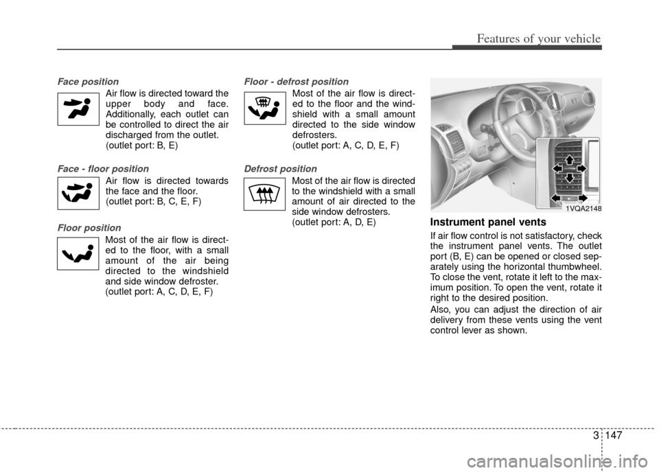
Instrument panel vents
If air flow control is not satisfactory, check
the instrument panel vents. The outlet
port (B, E) can be opened or closed sep-
arately using the horizontal thumbwheel.
To close the vent, rotate it left to the max-
imum position. To open the vent, rotate it
right to the desired position.
Also, you can adjust the direction of air
delivery from these vents using the vent
control lever as shown.
1VQA2148
Page 179 of 370
Features of your vehicle
162
3
Face position
Air flow is directed toward the
upper body and face.
Additionally, each outlet can be controlled to direct the air
discharged from the outlet.
(outlet port: B, E)
Face - floor position
Air flow is directed towardsthe face and the floor.
(outlet port: B, C, E, F)
Floor position
Most of the air flow is direct-ed to the floor, with a small
amount of the air being
directed to the windshield
and side window defroster.
(outlet port: A, C, D, E, F)
Floor - defrost position
Most of the air flow is direct-ed to the floor and the wind-
shield with a small amount
directed to the side window
defrosters.
(outlet port: A, C, D, E, F)
Defrost button
Most of the air flow is directed to the
windshield with a small amount of air
directed to the side window defrosters.
(outlet port: A, D, E)
OVQ049328