Page 107 of 342

433
Features of your vehicle
✽
✽NOTICE
The following symptoms may occur dur-
ing normal vehicle operation:
• The EPS warning light does not illu-
minate.
• The steering wheel becomes heavier after turning the ignition switch on.
This happens as the system performs
the EPS system diagnostics. When the
diagnostics is completed, the steering
wheel will return to its normal condi-
tion.
• Click noise may be heard from the EPS relay after the ignition switch is
turned to the ON or LOCK position.
• Motor noise may be heard when the vehicle is at a stop or at a low driving
speed.
• If the Electric Power Steering System does not operate normally, the warn-
ing light will illuminate on the instru-
ment cluster. The steering wheel may
become difficult to control or operate
abnormally. Take your vehicle to an
authorized KIA dealer and have the
vehicle checked as soon as possible.
• When you operate the steering wheel in low temperature, abnormal noise
could occur. If temperature rises, the
noise will disappear. This is a normal
condition.
D130300AFD
Tilt steering (if equipped)
Tilt steering allows you to adjust the
steering wheel before you drive. You can
also raise it to give your legs more room
when you exit and enter the vehicle.
The steering wheel should be positioned
so that it is comfortable for you to drive,
while permitting you to see the instru-
ment panel warning lights and gauges.
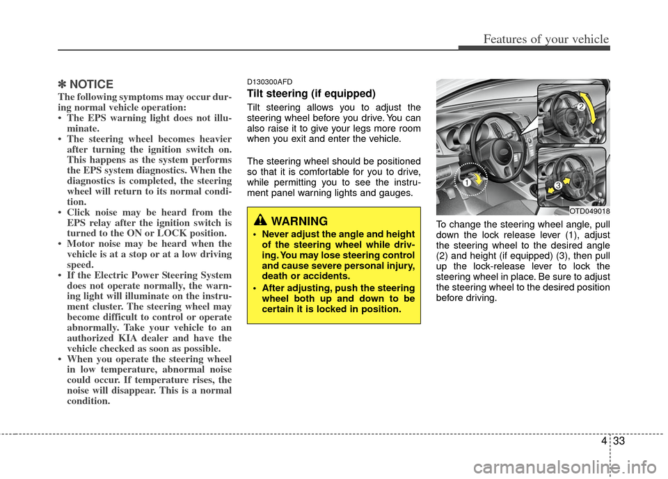
To change the steering wheel angle, pull
down the lock release lever (1), adjust
the steering wheel to the desired angle
(2) and height (if equipped) (3), then pull
up the lock-release lever to lock the
steering wheel in place. Be sure to adjust
the steering wheel to the desired position
before driving.
WARNING
Never adjust the angle and heightof the steering wheel while driv-
ing. You may lose steering control
and cause severe personal injury,
death or accidents.
After adjusting, push the steering wheel both up and down to be
certain it is locked in position.
OTD049018
Page 318 of 342
743
Maintenance
✽
✽NOTICE
Not all fuse panel descriptions in this
manual may be applicable to your vehi-
cle. It is accurate at the time of printing.
When you inspect the fuse box on your
vehicle, refer to the fuse box label.
Engine compartment fuse panel
OTD079026/OTD079027
G210300ATD-EC
Fuse/Relay panel description
Inside the fuse/relay box covers, you can find the fuse/relay label describing fuse/relay
name and capacity.
Instrument panel fuse panel
Page 319 of 342

Maintenance
44
7
Instrument panel fuse panel
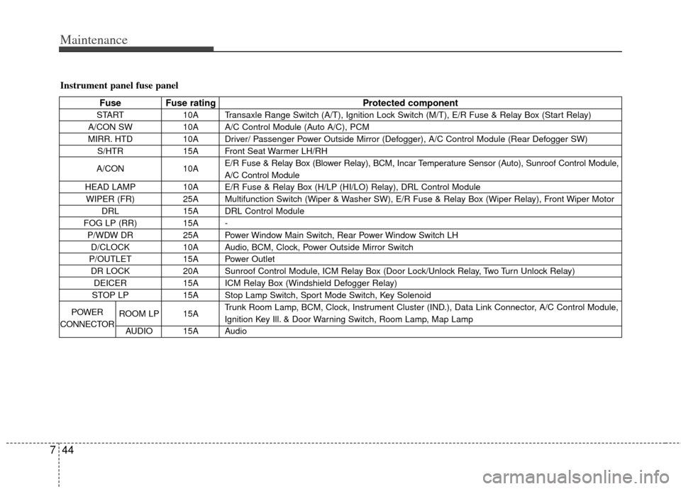
Fuse Fuse rating Protected component
START10A Transaxle Range Switch (A/T), Ignition Lock Switch (M/T), E/R Fuse & Relay Box (Start Relay)
A/CON SW 10A A/C Control Module (Auto A/C), PCM
MIRR. HTD 10A Driver/ Passenger Power Outside Mirror (Defogger), A/C Control Module (Rear Defogger SW)
S/HTR 15A Front Seat Warmer LH/RH
A/CON 10AE/R Fuse & Relay Box (Blower Relay), BCM, Incar Temperature Sensor (Auto), Sunroof Control Module,
A/C Control Module
HEAD LAMP 10A E/R Fuse & Relay Box (H/LP (HI/LO) Relay), DRL Control Module
WIPER (FR) 25A Multifunction Switch (Wiper & Washer SW), E/R Fuse & Relay Box (Wiper Relay), Front Wiper Motor
DRL 15A DRL Control Module
FOG LP (RR) 15A -
P/WDW DR 25A Power Window Main Switch, Rear Power Window Switch LH
D/CLOCK 10A Audio, BCM, Clock, Power Outside Mirror Switch
P/OUTLET 15A Power Outlet
DR LOCK 20A Sunroof Control Module, ICM Relay Box (Door Lock/Unlock Relay, Two Turn Unlock Relay)
DEICER 15A ICM Relay Box (Windshield Defogger Relay)
STOP LP 15A Stop Lamp Switch, Sport Mode Switch, Key Solenoid
ROOM LP 15A Trunk Room Lamp, BCM, Clock, Instrument Cluster (IND.), Data Link Connector, A/C Control Module,
Ignition Key Ill. & Door Warning Switch, Room Lamp, Map Lamp
AUDIO 15A Audio
POWER
CONNECTOR
Page 320 of 342
745
Maintenance
Fuse Fuse ratingProtected component
TRUNK OPEN 15A Trunk Open Relay
PDM 25A -
SAFETY P/WDW 25A - P/WDW ASS 25A Power Window Main Switch, Passenger Power Window Switch, Rear Power Window Switch RHP/OUTLET 15A Power OutletT/SIG LP 10A Hazard Switch
A/BAG IND 10A Instrument Cluster (IND.) CLUSTER 10A Instrument Cluster (IND.), BCM, Electronic Chromic Mirror, Rheostat, Steering Angle Sensor A/BAG 15A SRS Control Module
IGN1-A 15A PDM, EPMESC Switch, EPS Control Module Control Module
HAZARD LP 15A ICM Relay Box (Hazard Relay), Hazard Switch
TAIL LP (RH) 10A Rear Combination Lamp (In/Out) RH, Head Lamp RH, Shunt Connector, Passenger Power Window Switch,
License Lamp RH (4DR), Illuminations, Rheostat Relay (With DRL)
TAIL LP (LH) 10A Head Lamp LH, Rear Combination Lamp (In/Out) LH, Power Window Main Switch,
License Lamp (2DR), License Lamp LH (4DR)
Page 321 of 342

Maintenance
46
7
Engine compartment fuse panel
Description Fuse rating Protected component
ALT125AGenerator, Fuse (MDPS, HTD GLASS, C/FAN, ABS 2, BLOWER, IGN 1, FOG LP (FR), ABS 1)
MDPS 80A EPS Control Module
ABS 2 40A ESC Control Module, ABS Control Module
C/FAN 40A C/Fan LO/HI Relay
BLOWER 40A Blower Relay
HTD GLASS 40A I/P Junction Box (Rear Defogger Relay) IGN 2 30A Ignition Switch, Start Relay, Button Relay Box (ESCL Relay)
BATT 1 50AI/P Junction Box (Fuse (TAIL LAMP (LH/RH), P/WDW DR, P/WDW ASS, FOG LP (RR)/SSB,
SMK, PDM), Tail Lamp Relay, Power Window Relay)
ABS 1 40A ESC Control Module, ABS Control Module
IGN 1 30A Ignition Switch, Button Relay Box (ESCL Relay (IGN1))
BATT 2 50AI/P Junction Box (Power Connector (AUDIO, ROOM LP LAMP), FUSE (STOP LP, DEICER,
HAZARD LP, DR LOCK, TRUNK OPEN))
ECU 30A Engine Control Relay
FOG LP (FR) 10A Multipurpose Check Connector, Front Fog Relay, Battery Sensor H/LP HI 20A H/LP (HI) Relay,
HORN 10A Horn Relay
H/LP LO(LH) 10A Head Lamp LH
H/LP LO(RH) 10A Head Lamp RH SPARE 10A -
SNSR 3 10A ECM, PCM, Vehicle Speed Sensor, Pulse Generator 'A', Stop Lamp Switch
ABS 10A Multipurpose Check Connector, ESC Control Module, ABS Control Module
ECU 3 15A Ignition Coil (#1~#4), Condenser, PCM
MULTI
FUSE
FUSE
Page 322 of 342
747
Maintenance
Description Fuse ratingProtected component
B/UP LP10A Inhibitor Switch, Pulse Generater 'B', Back Up Lamp Switch
SPARE 15A -
SPARE 20A -
IGN COIL 20A Condenser (G4KF), Ignition Coil #1~4
SNSR 2 10AOil Control Valve (#1, #2), Camshaft Position Sensor (Intake, Exhaust), F/PUMP Relay,
C/FAN LO Relay, Immobilizer Module
ECU 2 10A PCM, Purge Control Solenoid Valve, Oxygen Sensor (Down)
INJECTOR 10A A/CON Relay, Crankshaft Position Sensor, Oxygen Sensor (UP), Injector #1~4,
Variable Intake Sensor
SNSR 1 15A PCM, Canister Close Valve
ECU 1 10A PCM
A/CON 10A A/CON Relay
F/PUMP 15A F/FUMP Relay
FUSE