Page 149 of 490
2. Move the safety catch located under the front edge of
the hood, near the center and raise the hood.
Lift the hood prop rod, clipped to the right side (left side
facing hood) of the engine compartment, to secure the
hood in the open position. Place the hood prop at the
location stamped into the inner hood surface.CAUTION!
To prevent possible damage, do not slam the hood to
close it. Lower the hood until it is open approxi-
mately 8 in (20 cm) and then drop it. This should
secure both latches. Never drive your vehicle unless
the hood is fully closed, with both latches engaged.
WARNING!
Be sure the hood is fully latched before driving your
vehicle. If the hood is not fully latched, it could open
when the vehicle is in motion and block your vision.
Failure to follow this warning could result in serious
injury or death.
Safety Catch
3
UNDERSTANDING THE FEATURES OF YOUR VEHICLE 147
Page 154 of 490

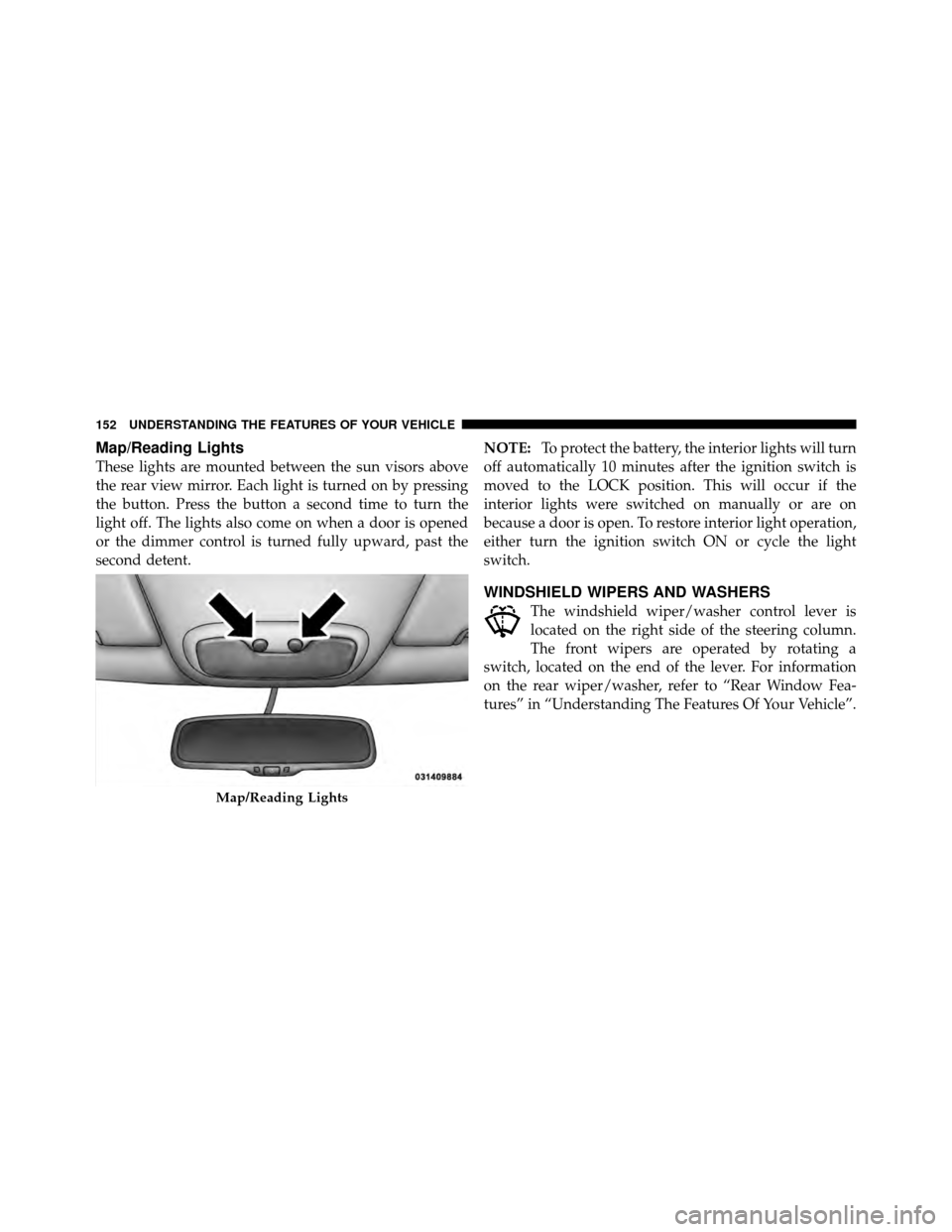
Map/Reading Lights
These lights are mounted between the sun visors above
the rear view mirror. Each light is turned on by pressing
the button. Press the button a second time to turn the
light off. The lights also come on when a door is opened
or the dimmer control is turned fully upward, past the
second detent.NOTE:
To protect the battery, the interior lights will turn
off automatically 10 minutes after the ignition switch is
moved to the LOCK position. This will occur if the
interior lights were switched on manually or are on
because a door is open. To restore interior light operation,
either turn the ignition switch ON or cycle the light
switch.
WINDSHIELD WIPERS AND WASHERS
The windshield wiper/washer control lever is
located on the right side of the steering column.
The front wipers are operated by rotating a
switch, located on the end of the lever. For information
on the rear wiper/washer, refer to “Rear Window Fea-
tures” in “Understanding The Features Of Your Vehicle”.
Map/Reading Lights
152 UNDERSTANDING THE FEATURES OF YOUR VEHICLE
Page 156 of 490
Windshield Wiper Operation
Rotate the end of the lever upward to the second detent
past the intermittent settings for low-speed wiper opera-
tion.
Rotate the end of the lever upward to the third detent
past the intermittent settings for high-speed wiper opera-
tion.
Intermittent Wiper System
Use the intermittent wiper when weather conditions
make a single wiping cycle, with a variable pause be-
tween cycles, desirable. Select the delay interval by
turning the end of the lever. Rotate the end of the lever
upward (clockwise) to decrease the delay time and
downward (counterclockwise) to increase the delay time.
The delay can be regulated from a maximum of approxi-
mately 18 seconds between cycles, to a cycle every
second.
NOTE:The wiper delay times depend on vehicle speed.
If the vehicle is moving less than 10 mph (16 km/h),
delay times will be doubled.
Wiper Control
154 UNDERSTANDING THE FEATURES OF YOUR VEHICLE
Page 158 of 490
TILT STEERING COLUMN
This feature allows you to tilt the steering column
upward or downward. The tilt control handle is located
on the left side of the steering column, below the turn
signal lever.
Push down on the lever to unlock the steering column.
With one hand firmly on the steering wheel, move the
steering column up or down, as desired. Push the lever
up to lock the steering column firmly in place.
Tilting Steering Column Control
156 UNDERSTANDING THE FEATURES OF YOUR VEHICLE
Page 159 of 490
WARNING!
Do not adjust the steering column while driving.
Adjusting the steering column while driving or driv-
ing with the steering column unlocked, could cause
the driver to lose control of the vehicle. Be sure the
steering column is locked before driving your ve-
hicle. Failure to follow this warning may result in
serious injury or death.
ELECTRONIC SPEED CONTROL — IF EQUIPPED
When engaged, the Electronic Speed Control takes over
accelerator operations at speeds greater than 25 mph
(40 km/h).
The Electronic Speed Control buttons are located on the
right side of the steering wheel.NOTE:
In order to ensure proper operation, the Elec-
tronic Speed Control System has been designed to shut
down if multiple Speed Control functions are operated at
the same time. If this occurs, the Electronic Speed Control1 — ON/OFF 2 — RES +
4 — CANCEL 3 — SET -
3
UNDERSTANDING THE FEATURES OF YOUR VEHICLE 157
Page 166 of 490

Gate Operator/Canadian Programming
Canadian radio-frequency laws require transmitter sig-
nals to “time-out” (or quit) after several seconds of
transmission – which may not be long enough for
HomeLink�to pick up the signal during programming.
Similar to this Canadian law, some U.S. gate operators are
designed to “time-out” in the same manner.
It may be helpful to unplug the device during the cycling
process to prevent possible overheating of the garage
door or gate motor.
If you are having difficulties programming a garage door
opener or a gate operator, replace “Programming
HomeLink�” Step 3 with the following: 3. Continue to press and hold the HomeLink�
button,
while you press and release (“cycle”), your handheld
transmitter every two seconds until HomeLink� has
successfully accepted the frequency signal. The indica-
tor light will flash slowly and then rapidly when fully
trained.
If you unplugged the device for training, plug it back in
at this time.
Then proceed with Step 4 under “Programming
HomeLink�” earlier in this section.
Using HomeLink�
To operate, press and release the programmed
HomeLink� button. Activation will now occur for the
trained device (i.e., garage door opener, gate operator,
Security system, entry door lock, home/office lighting,
etc.,). The handheld transmitter of the device may also be
used at any time.
164 UNDERSTANDING THE FEATURES OF YOUR VEHICLE
Page 171 of 490

Wind Buffeting
Wind buffeting can be described as the perception of
pressure on the ears or a helicopter-type sound in the
ears. Your vehicle may exhibit wind buffeting with the
windows down, or the sunroof (if equipped) is in certain
open or partially open positions. This is a normal occur-
rence and can be minimized. If the buffeting occurs with
the rear windows open, open the front and rear windows
together to minimize the buffeting. If the buffeting occurs
with the sunroof open, adjust the sunroof opening to
minimize the buffeting or open any window.
Sunroof Maintenance
Use only a non-abrasive cleaner and a soft cloth to clean
the glass panel.
Ignition Off Operation
For vehicles not equipped with the Electronic Vehicle
Information Center (EVIC), the power sunroof switch
will remain active for 45 seconds after the ignition switch
is turned to the LOCK position. Opening either front
door will cancel this feature.
For vehicles equipped with the EVIC, the power sunroof
switch will remain active for up to approximately ten
minutes after the ignition switch is turned to the LOCK
position. Opening either front door will cancel this
feature. The time is programmable. Refer to “Electronic
Vehicle Information Center (EVIC)/Personal Settings
(Customer-Programmable Features)” in “Understanding
Your Instrument Panel” for further information.
3
UNDERSTANDING THE FEATURES OF YOUR VEHICLE 169
Page 188 of 490

NOTE:If not equipped with crossbars, your authorized
dealer can order and install MOPAR� crossbars built
specifically for this roof rack system.
Distribute cargo weight evenly on the roof rack crossbars.
The roof rack does not increase the total load carrying
capacity of the vehicle. Be sure the total load of cargo
inside the vehicle plus that on the external rack does not
exceed the maximum vehicle load capacity.
The optional crossbars must also be secured in one of the
seven detent positions marked with an arrow on the
siderails to prevent movement. To move the crossbars,
loosen the thumb screws located at the upper edge of
each crossbar approximately eight turns, then move the
crossbar to the desired position, keeping the crossbars
parallel to the rack frame. Once the crossbar is in one of
the seven detent positions, retighten the thumb screws to
lock the crossbar into position. NOTE:
•To help control wind noise when the crossbars are not
in use, place the front crossbar in the first detent from
the front of the vehicle and the rear crossbar in the
second detent from the rear of the vehicle.
•If the rear crossbar (or any metallic object) is placed
over the satellite radio antenna (if equipped), you may
experience interruption of satellite radio reception. For
improved satellite radio reception, place the rear cross-
bar in the second detent from the rear of the vehicle
when not in use.
•The grab handles on the back of the vehicle (if
equipped) are not to be used as a towing feature.
186 UNDERSTANDING THE FEATURES OF YOUR VEHICLE