Page 291 of 490

�Tire Safety Information ................. 328
▫ Tire Markings ....................... 328
▫ Tire Identification Number (TIN) ......... 332
▫ Tire Terminology And Definitions ......... 333
▫ Tire Loading And Tire Pressure .......... 334
� Tires — General Information ............. 338
▫ Tire Pressure ....................... 338
▫ Tire Inflation Pressures ................ 339
▫ Tire Pressures For High Speed Operation . . . 341
▫ Radial Ply Tires ..................... 341
▫ Spare Tire Matching Original Equipped Tire
And Wheel – If Equipped .............. 341
▫ Compact Spare Tire – If Equipped ........ 342▫
Full Size Spare – If Equipped ............ 343
▫ Limited-Use Spare – If Equipped ......... 343
▫ Tire Spinning ....................... 344
▫ Tread Wear Indicators ................. 345
▫ Life Of Tire ........................ 345
▫ Replacement Tires .................... 346
� Tire Chains .......................... 347
� Snow Tires .......................... 347
� Tire Rotation Recommendations ........... 348
� Tire Pressure Monitoring System (TPMS) ..... 349
▫ Base System ........................ 351
▫ Premium System – If Equipped .......... 353
▫ General Information .................. 357
5
STARTING AND OPERATING 289
Page 307 of 490
CAUTION!
On icy or slippery roads, do not downshift at high
engine RPM’s or vehicle speeds because engine brak-
ing may cause skidding and loss of control.
Mud
Deep mud creates a great deal of suction around the tires
and is very difficult to get through. You should use low (L
Off-Road) with the 4WD LOCK engaged and maintain
your momentum. If you start to slow to a stop, try
turning your steering wheel no more than a 1/4 turn
quickly back and forth for additional traction. Mud holes
pose an increased threat of vehicle damage and getting
stuck. They are normally full of debris from previous
vehicles getting stuck. As a good practice before entering
any mud hole, get out and determine how deep it is, if
there are any hidden obstacles and if the vehicle can be
safely recovered if stuck.
Sand
Soft sand is very difficult to travel through with full tire
pressure. When crossing soft sandy spots in a trail
maintain your vehicle’s momentum and do not stop. The
key to driving in soft sand is using the appropriate tire
pressure, accelerating slowly, avoiding abrupt maneu-
vers and maintaining the vehicle’s momentum. If you are
going to be driving on large soft sandy areas or dunes,
reduce your tire pressure to a minimum of 15 psi
(103 kPa) to allow for a greater tire surface area. You
should use low (L Off-Road) with the 4WD LOCK
engaged and ESC turned off. Reduced tire pressure will
drastically improve your traction and handling, while
driving on the soft sand, but you must return the tires to
normal air pressure before driving on pavement or other
hard surfaces. Be sure you have a way to reinflate the
tires prior to reducing the pressure.
5
STARTING AND OPERATING 305
Page 308 of 490
CAUTION!
Reduced tire pressures may cause tire unseating and
total loss of air pressure. To reduce the risk of tire
unseating, while at a reduced tire pressure, reduce
your speed and avoid sharp turns or abrupt maneu-
vers.
Hill Climbing
Hill climbing requires good judgment and a good under-
standing of your abilities and your vehicle’s limitations.
Hills can cause serious problems. Some are just too steep
to climb and should not be attempted. You should always
feel confident with the vehicle and your abilities. You
should always climb hills straight up and down. Never
attempt to climb a hill on an angle.
Before Climbing A Steep Hill
As you approach a hill consider its grade or steepness.
Determine if it is too steep. Look to see what the traction
is on the hill side trail. Is the trail straight up and down?
What is on top and the other side? Are there ruts, rocks,
branches or other obstacles on the path? Can you safely
recover the vehicle if something goes wrong? If every-
thing looks good and you feel confident, then you should
use low (L Off-Road) with the 4WD LOCK engaged and
proceed with caution maintaining your momentum as
you climb the hill.
Driving Up Hill
Once you have determined your ability to proceed and
have shifted into the appropriate gear, line your vehicle
up for the straightest possible run. Accelerate with an
easy constant throttle and apply more power as you start
up the hill. Do not race forward into a steep grade, the
abrupt change of grade could cause you to lose control. If
the front end begins to bounce, ease off the throttle
306 STARTING AND OPERATING
Page 321 of 490
All vehicle wheels and tires must be the same size and
type and tires must be properly inflated to produce
accurate signals for the computer.
ELECTRONIC BRAKE CONTROL SYSTEM
Your vehicle may be equipped with an optional ad-
vanced electronic brake control system that includes
Anti-Lock Brake System (ABS), Brake Assist System
(BAS), Traction Control System (TCS), Electronic Roll
Mitigation (ERM), Hill Descent Control (HDC), Hill Start
Assist (HSA), and Electronic Stability Control (ESC). All
systems work together to enhance vehicle stability and
control in various driving conditions and are commonly
referred to as ESC.
Anti-Lock Brake System (ABS)
This system aids the driver in maintaining vehicle control
under adverse braking conditions. The system controls
hydraulic brake pressure to prevent wheel lockup andhelp avoid skidding on slippery surfaces during braking.
Refer to “Anti-Lock Brake System” in “Starting and
Operating” for further information.
Brake Assist System (BAS)
The BAS is designed to optimize the vehicle’s braking
capability during emergency braking maneuvers. The
system detects an emergency braking situation by sens-
ing the rate and amount of brake application and then
applies optimum pressure to the brakes. This can help
reduce braking distances. The BAS complements the
Anti-Lock Brake System (ABS). Applying the brakes very
quickly results in the best BAS assistance. To receive the
benefit of the system, you must apply
continuousbrak-
ing pressure during the stopping sequence (do not
“pump” the brakes). Do not reduce brake pedal pressure
unless braking is no longer desired. Once the brake pedal
is released, the BAS is deactivated.
5
STARTING AND OPERATING 319
Page 330 of 490
Malfunction Indicator Light” begins to flash during ac-
celeration, ease up on the accelerator and apply as little
throttle as possible. Be sure to adapt your speed and
driving to the prevailing road conditions.
NOTE:
•The “ESC Activation/Malfunction Indicator Light”
and the “ESC OFF Indicator Light” come on momen-
tarily each time the ignition switch is turned ON.
•Each time the ignition is turned ON, the ESC system
will be ON even if it was turned off previously.
•The ESC system will make buzzing or clicking sounds
when it is active. This is normal; the sounds will stop
when ESC becomes inactive following the maneuver
that caused the ESC activation.The “ESC OFF Indicator Light” indicates the
Electronic Stability Control (ESC) is off.
TIRE SAFETY INFORMATION
Tire Markings
1 — U.S. DOT Safety
Standards Code (TIN) 4 — Maximum Load
2 — Size Designation 5 — Maximum Pressure
3 — Service Description 6 — Treadwear, Traction and Temperature Grades
328 STARTING AND OPERATING
Page 331 of 490
NOTE:
•P (Passenger) - Metric tire sizing is based on U.S.
design standards. P-Metric tires have the letter “P”
molded into the sidewall preceding the size designa-
tion. Example: P215/65R15 95H.
•European-Metric tire sizing is based on European
design standards. Tires designed to this standard have
the tire size molded into the sidewall beginning with
the section width. The letter�P�is absent from this tire
size designation. Example: 215/65R15 96H.
•LT (Light Truck) - Metric tire sizing is based on U.S.
design standards. The size designation for LT-Metric tires is the same as for P-Metric tires except for the
letters “LT” that are molded into the sidewall preced-
ing the size designation. Example: LT235/85R16.
•Temporary spare tires are high-pressure compact
spares designed for temporary emergency use only.
Tires designed to this standard have the letter “T”
molded into the sidewall preceding the size designa-
tion. Example: T145/80D18 103M.
•High flotation tire sizing is based on U.S. design
standards and it begins with the tire diameter molded
into the sidewall. Example: 31x10.5 R15 LT.5
STARTING AND OPERATING 329
Page 333 of 490
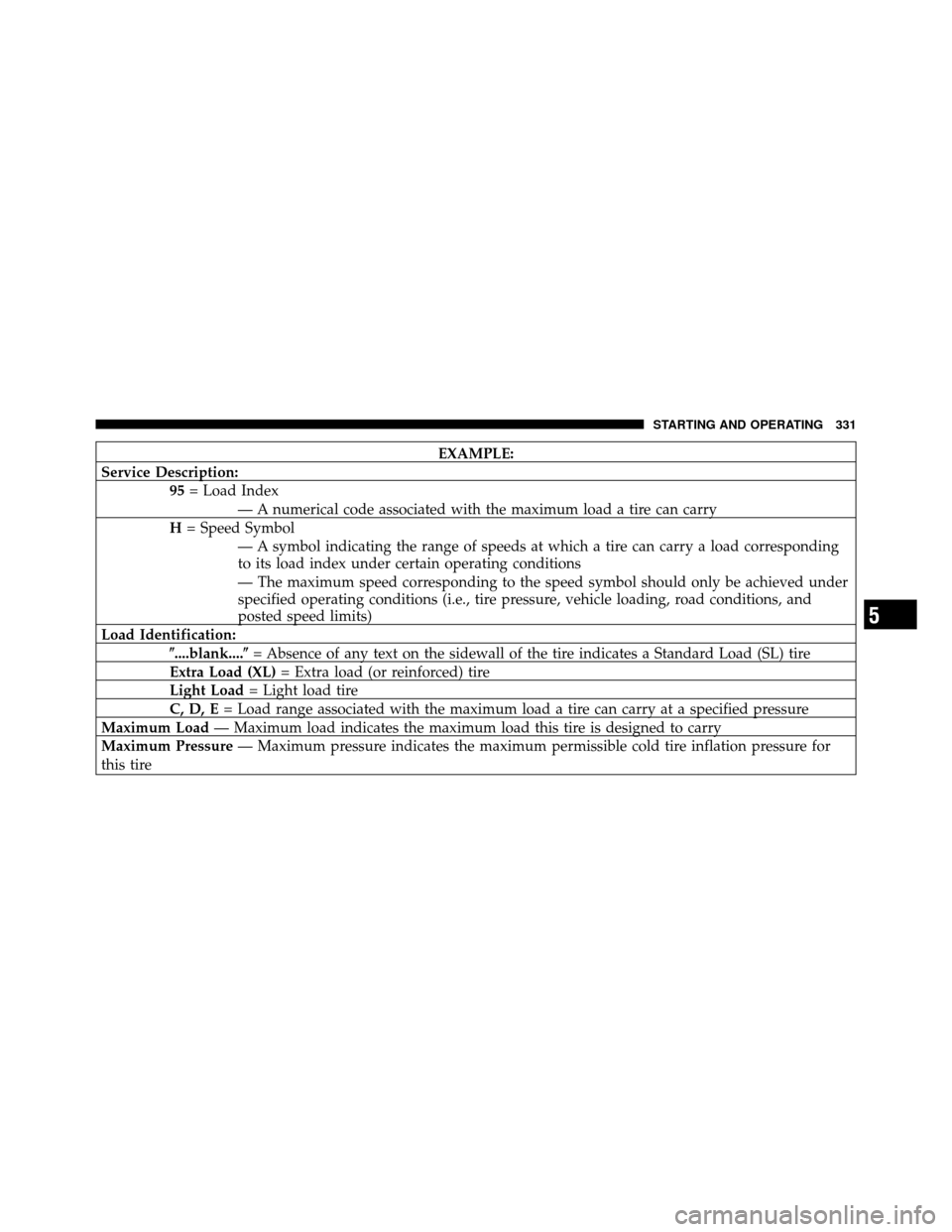
EXAMPLE:
Service Description: 95= Load Index
— A numerical code associated with the maximum load a tire can carry
H = Speed Symbol
— A symbol indicating the range of speeds at which a tire can carry a load corresponding
to its load index under certain operating conditions
— The maximum speed corresponding to the speed symbol should only be achieved under
specified operating conditions (i.e., tire pressure, vehicle loading, road conditions, and
posted speed limits)
Load Identification: �....blank....� = Absence of any text on the sidewall of the tire indicates a Standard Load (SL) tire
Extra Load (XL) = Extra load (or reinforced) tire
Light Load = Light load tire
C, D, E = Load range associated with the maximum load a tire can carry at a specified pressure
Maximum Load — Maximum load indicates the maximum load this tire is designed to carry
Maximum Pressure — Maximum pressure indicates the maximum permissible cold tire inflation pressure for
this tire
5
STARTING AND OPERATING 331
Page 335 of 490
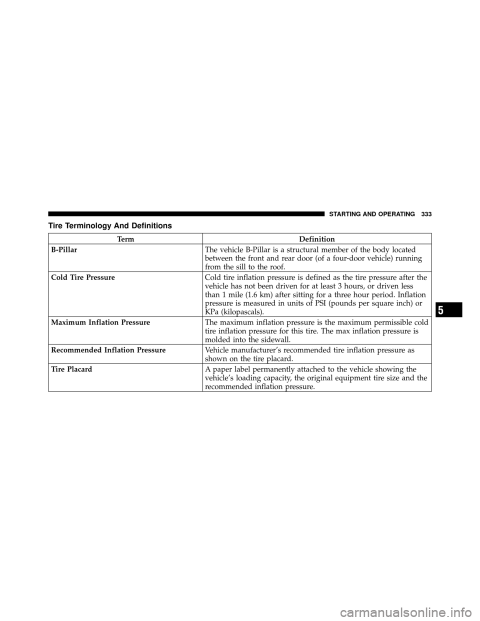
Tire Terminology And Definitions
TermDefinition
B-Pillar The vehicle B-Pillar is a structural member of the body located
between the front and rear door (of a four-door vehicle) running
from the sill to the roof.
Cold Tire Pressure Cold tire inflation pressure is defined as the tire pressure after the
vehicle has not been driven for at least 3 hours, or driven less
than 1 mile (1.6 km) after sitting for a three hour period. Inflation
pressure is measured in units of PSI (pounds per square inch) or
KPa (kilopascals).
Maximum Inflation Pressure The maximum inflation pressure is the maximum permissible cold
tire inflation pressure for this tire. The max inflation pressure is
molded into the sidewall.
Recommended Inflation Pressure Vehicle manufacturer’s recommended tire inflation pressure as
shown on the tire placard.
Tire Placard A paper label permanently attached to the vehicle showing the
vehicle’s loading capacity, the original equipment tire size and the
recommended inflation pressure.
5
STARTING AND OPERATING 333