Page 362 of 587
4WD LOW
This range is for low speed four-wheel drive. It locks the
front and rear driveshafts together and forces the front
and rear wheels to rotate at the same speed. It provides
additional traction and maximum pulling power for
loose, slippery road surfaces only. Do not exceed 25 mph
(40 km/h).
NOTE:Refer to “Selec-Terrain� – If Equipped” for
further information on the various positions and their
intended usages.
Shifting Procedures
4WDHIto4WDLOW
With the vehicle at speeds of 0 to 3 mph (0 to 5 km/h), the
ignition switch in the ON position or the engine running,
shift the transmission into NEUTRAL, and press the
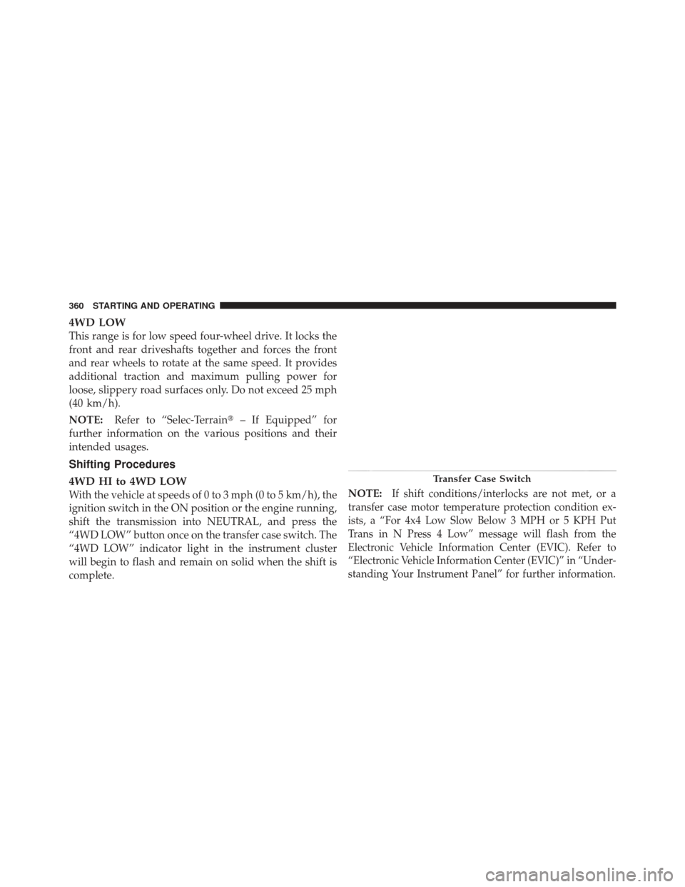
“4WD LOW” button once on the transfer case switch. The
“4WD LOW” indicator light in the instrument cluster
will begin to flash and remain on solid when the shift is
complete. NOTE:If shift conditions/interlocks are not met, or a
transfer case motor temperature protection condition ex-
ists, a “For 4x4 Low Slow Below 3 MPH or 5 KPH Put
Trans in N Press 4 Low” message will flash from the
Electronic Vehicle Information Center (EVIC). Refer to
“Electronic Vehicle Information Center (EVIC)” in “Under-
standing Your Instrument Panel” for further information.
Transfer Case Switch
360 STARTING AND OPERATING
Page 363 of 587
4WD LOW to 4WD HI
With the vehicle at speeds of 0 to 3 mph (0 to 5 km/h), the
ignition switch in the ON position or the engine running,
shift the transmission into NEUTRAL, and press the
“4WD LOW” button once on the transfer case switch. The
“4WD LOW” indicator light in the instrument cluster
will flash and go out when the shift is complete.
NOTE:
•If shift conditions/interlocks are not met, or a transfer
case motor temperature protection condition exists, a
“For 4x4 High Slow Below 3 MPH or 5 KPH Put Trans
in N Press 4 Low” message will flash from the
Electronic Vehicle Information Center (EVIC). Refer to
“Electronic Vehicle Information Center (EVIC)” in
“Understanding Your Instrument Panel” for further
information.
•Shifting into or out of 4WD LOW is possible with the
vehicle completely stopped; however, difficulty mayoccur due to the mating clutch teeth not being prop-
erly aligned. Several attempts may be required for
clutch teeth alignment and shift completion to occur.
The preferred method is with the vehicle rolling 0 to
3 mph (0 to 5 km/h). If the vehicle is moving faster
than 3 mph (5 km/h), the transfer case will not allow
the shift.
NEUTRAL Shift Procedure
1. Turn the ignition switch to the ON position, engine off.
2. Vehicle stopped, with foot on brake.
3. Place the transmission into NEUTRAL.
4. Hold down the NEUTRAL “pin” switch (with a pen,
etc.) for four seconds until the LED light by the switch
starts to blink indicating shift in progress. The light will
stop blinking (stay on solid) when the NEUTRAL shift is
complete. A “To Tow Vehicle Safely, Read Neutral Shift
Procedure in Owners Manual” message will display on5
STARTING AND OPERATING 361
Page 381 of 587
MULTI-DISPLACEMENT SYSTEM (MDS)
(IF EQUIPPED) — 5.7L ENGINE ONLY
This feature offers improved fuel economy by shutting
off four of the engine’s eight cylinders during light load
and cruise conditions. The system is automatic with no
driver inputs or additional driving skills required.
NOTE:The MDS system may take some time to return
to full functionality after a battery disconnect.
PARKING BRAKE
Before leaving the vehicle, make sure that the parking
brake is fully applied and place the shift lever in the
PARK position.
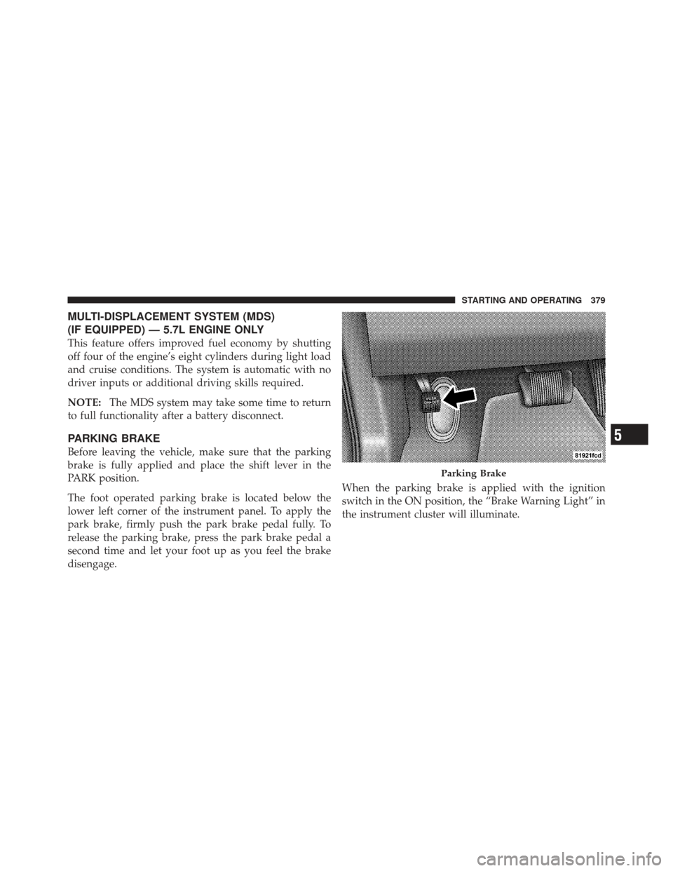
The foot operated parking brake is located below the
lower left corner of the instrument panel. To apply the
park brake, firmly push the park brake pedal fully. To
release the parking brake, press the park brake pedal a
second time and let your foot up as you feel the brake
disengage. When the parking brake is applied with the ignition
switch in the ON position, the “Brake Warning Light” in
the instrument cluster will illuminate.
Parking Brake
5
STARTING AND OPERATING 379
Page 386 of 587

WARNING!
Many factors, such as vehicle loading, road condi-
tions and driving conditions, influence the chance
that wheel lift or rollover may occur. ERM cannot
prevent all wheel lift or rollovers, especially those
that involve leaving the roadway or striking objects
or other vehicles. The capabilities of an ERM-
equipped vehicle must never be exploited in a reck-
less or dangerous manner which could jeopardize the
user ’s safety or the safety of others.
Electronic Stability Control (ESC)
This system enhances directional control and stability of
the vehicle under various driving conditions. ESC cor-
rects for oversteering or understeering of the vehicle by
applying the brake of the appropriate wheel to assist in
counteracting the oversteer or understeer condition. En-
gine power may also be reduced to help the vehicle
maintain the desired path.ESC uses sensors in the vehicle to determine the vehicle
path intended by the driver and compares it to the actual
path of the vehicle. When the actual path does not match
the intended path, ESC applies the brake of the appro-
priate wheel to assist in counteracting the oversteer or
understeer condition.
•Oversteer - when the vehicle is turning more than
appropriate for the steering wheel position.
•Understeer - when the vehicle is turning less than
appropriate for the steering wheel position.
The “ESC Activation/Malfunction Indicator Light” lo-
cated in the instrument cluster will start to flash as soon
as the tires lose traction and the ESC system becomes
active. The “ESC Activation/Malfunction Indicator
Light” also flashes when the TCS is active. If the “ESC
Activation/Malfunction Indicator Light” begins to flash
during acceleration, ease up on the accelerator and apply
384 STARTING AND OPERATING
Page 393 of 587
When HDC is enabled, the HDC icon will be illuminated
in the instrument cluster. HDC will automatically apply
the brakes to control downhill speed to the selected level
when necessary on grades greater than approximately
8%. It will usually not activate on level ground.The HDC speed may be adjusted by the driver to suit the
driving conditions. The speed corresponds to the trans-
mission gear selected.
HDC operation can be overridden with brake application
to slow the vehicle down below the HDC control speed.
Conversely, if more speed is desired during HDC control,
the accelerator pedal will increase vehicle speed in the
usual manner. When either the brake or the accelerator is
released, HDC will control the vehicle back to the origi-
nal set speed.
HDC Operation in 4WD Low Range
To enable HDC, press the HDC switch or put the
Selec-Terrain™ system in the “ROCK” mode. The HDC
icon will be illuminated in the instrument cluster and
HDC will function. If the vehicle speed goes above
20 mph (32 km/h), the HDC icon will flash and HDC will
not function. To disable HDC, press the HDC switch.Hill Descent Switch
5
STARTING AND OPERATING 391
Page 394 of 587
4WD Low Range Set Speeds
•1st = 1 mph (1.6 km/h)
•2nd = 2.5 mph (4 km/h)
•3rd = 4 mph (6 km/h)
•4th = 5.5 mph (9 km/h)
•5th or D (Drive) = 7.5 mph (12 km/h)
•REVERSE = 1 mph (1.6 km/h)
•NEUTRAL = 2.5 mph (4 km/h)
•PARK = HDC will not function
HDC is intended for low speed off-road driving only.
At vehicle speeds above 20 mph (32 km/h), HDC will no
longer function. When the vehicle speed drops below
20 mph (32 km/h), HDC function will automatically
resume and the vehicle speed will return to the chosen set
speed.
WARNING!
HDC is only intended to assist the driver in control-
ling vehicle speed when descending hills. The driver
must remain attentive to the driving conditions and
is responsible for maintaining a safe vehicle speed.
ESC Activation/Malfunction Indicator Light and
ESC OFF Indicator Light
The “ESC Activation/Malfunction Indicator
Light” in the instrument cluster will come on
when the ignition switch is turned to the ON
position. It should turn off with the engine
running. If the “ESC Activation/Malfunction Indicator
Light” comes on continuously with the engine running, a
malfunction has been detected in the ESC system. If this
light remains on after several ignition cycles, and the
vehicle has been driven several miles (kilometers) at
392 STARTING AND OPERATING
Page 395 of 587
speeds greater than 30 mph (48 km/h), see your autho-
rized dealer as soon as possible to have the problem
diagnosed and corrected.
The “ESC Activation/Malfunction Indicator Light” (lo-
cated in the instrument cluster) starts to flash as soon as
the tires lose traction and the ESC system becomes active.
The “ESC Activation/Malfunction Indicator Light” also
flashes when TCS is active. If the “ESC Activation/
Malfunction Indicator Light” begins to flash during ac-
celeration, ease up on the accelerator and apply as little
throttle as possible. Be sure to adapt your speed and
driving to the prevailing road conditions.NOTE:
•The “ESC Activation/Malfunction Indicator Light”
and the “ESC OFF Indicator Light” come on momen-
tarily each time the ignition switch is turned ON.
•Each time the ignition is turned ON, the ESC system
will be ON even if it was turned off previously.
•The ESC system will make buzzing or clicking sounds
when it is active. This is normal; the sounds will stop
when ESC becomes inactive following the maneuver
that caused the ESC activation.
The “ESC OFF Indicator Light” indicates the
Electronic Stability Control (ESC) is off.
5
STARTING AND OPERATING 393
Page 420 of 587

The TPMS consists of the following components:
•Receiver Module
•Four Tire Pressure Monitoring Sensors
•Tire Pressure Monitoring Telltale Light
A low spare tire will not cause the Tire Pressure Moni-
toring Telltale Light to illuminate, a warning message to
appear, or the chime to sound. The Tire Pressure Monitoring Telltale Light will
illuminate in the instrument cluster, a “TIRE LOW
PRESSURE” message will display in the instru-
ment cluster for 5 seconds, and an audible chime will be
activated, when one or more of the four active road tire
pressures are low. Should this occur, you should stop as
soon as possible, check the inflation pressure of each tire
on your vehicle, and inflate each tire to the vehicle’s
recommended cold placard pressure value. The system will automatically update and the Tire Pressure Monitor-
ing Telltale Light will extinguish, once the updated tire
pressures have been received. The vehicle may need to be
driven for up to 20 minutes above 15 mph (24 km/h) to
receive this information.
The Tire Pressure Monitoring Telltale Light will flash on
and off for 75 seconds, and remain on solid when a
system fault is detected. In addition, a “SERVICE TPM
SYSTEM” message may be displayed for approximately
5 seconds when a system fault is detected, and a chime
will sound. If the ignition switch is cycled, this sequence
will repeat, providing the system fault still exists. The
Tire Pressure Monitoring Telltale Light will turn off when
the fault condition no longer exists. A system fault can
occur by any of the following:
1. Jamming due to electronic devices or driving next to
facilities emitting the same Radio Frequencies as the TPM
sensors.
418 STARTING AND OPERATING