2011 INFINITI QX56 warning
[x] Cancel search: warningPage 4986 of 5598

SRS AIR BAG WARNING LAMP DOES NOT TURN OFF
SRC-193
< SYMPTOM DIAGNOSIS >
C
D E
F
G
I
J
K L
M A
B
SRC
N
O P
SYMPTOM DIAGNOSIS
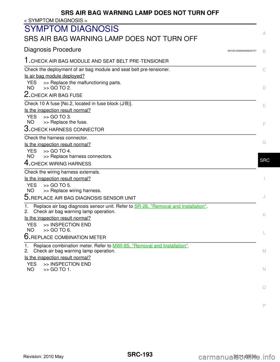
SRS AIR BAG WARNING LAMP DOES NOT TURN OFF
Diagnosis ProcedureINFOID:0000000006220157
1.CHECK AIR BAG MODULE AND SEAT BELT PRE-TENSIONER
Check the deployment of air bag m odule and seat belt pre-tensioner.
Is air bag module deployed?
YES >> Replace the malfunctioning parts.
NO >> GO TO 2.
2.CHECK AIR BAG FUSE
Check 10 A fuse [No.2, located in fuse block (J/B)].
Is the inspection result normal?
YES >> GO TO 3.
NO >> Replace the fuse.
3.CHECK HARNESS CONNECTOR
Check the harness connector.
Is the inspection result normal?
YES >> GO TO 4.
NO >> Replace harness connectors.
4.CHECK WIRING HARNESS
Check the wiring harness externals.
Is the inspection result normal?
YES >> GO TO 5.
NO >> Replace wiring harness.
5.REPLACE AIR BAG DIAGNOSIS SENSOR UNIT
1. Replace air bag diagnosis sensor unit. Refer to SR-26, "
Removal and Installation".
2. Check air bag warning lamp operation.
Is the inspection result normal?
YES >> INSPECTION END
NO >> GO TO 6.
6.REPLACE COMBINATION METER
1. Replace combination meter. Refer to MWI-85, "
Removal and Installation".
2. Check air bag warning lamp operation.
Is the inspection result normal?
YES >> INSPECTION END
NO >> GO TO 1.
Revision: 2010 May2011 QX56
Page 4987 of 5598

SRC-194
< SYMPTOM DIAGNOSIS >
SRS AIR BAG WARNING LAMP DOES NOT TURN ON
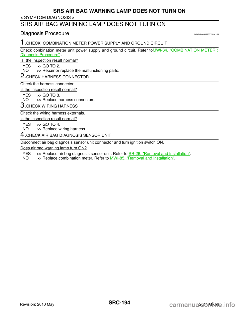
SRS AIR BAG WARNING LAMP DOES NOT TURN ON
Diagnosis ProcedureINFOID:0000000006220158
1.CHECK COMBINATION METER POWER SUPPLY AND GROUND CIRCUIT
Check conbination meter unit power supply and ground circuit. Refer to MWI-64, "
COMBINATION METER :
Diagnosis Procedure" .
Is the inspection result normal?
YES >> GO TO 2.
NO >> Repair or replace the malfunctioning parts.
2.CHECK HARNESS CONNECTOR
Check the harness connector.
Is the inspection result normal?
YES >> GO TO 3.
NO >> Replace harness connectors.
3.CHECK WIRING HARNESS
Check the wiring harness externals.
Is the inspection result normal?
YES >> GO TO 4.
NO >> Replace wiring harness.
4.CHECK AIR BAG DIAGNOSIS SENSOR UNIT
Disconnect air bag diagnosis sensor unit connector and turn ignition switch ON.
Does air bag warning lamp turn ON?
YES >> Replace air bag diagnosis sensor unit. Refer to SR-26, "Removal and Installation".
NO >> Replace combination meter. Refer to MWI-85, "
Removal and Installation".
Revision: 2010 May2011 QX56
Page 4990 of 5598

PRECAUTIONSST-3
< PRECAUTION >
C
DE
F
H I
J
K L
M A
B
ST
N
O P
PRECAUTION
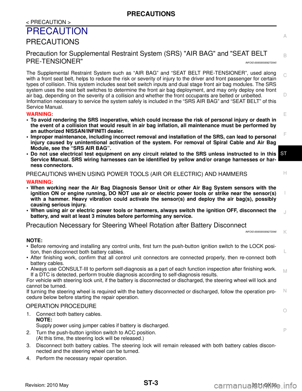
PRECAUTIONS
Precaution for Supplemental Restraint System (SRS) "AIR BAG" and "SEAT BELT
PRE-TENSIONER"
INFOID:0000000006272045
The Supplemental Restraint System such as “A IR BAG” and “SEAT BELT PRE-TENSIONER”, used along
with a front seat belt, helps to reduce the risk or severi ty of injury to the driver and front passenger for certain
types of collision. This system includes seat belt switch inputs and dual stage front air bag modules. The SRS
system uses the seat belt switches to determine the front air bag deployment, and may only deploy one front
air bag, depending on the severity of a collision and whether the front occupants are belted or unbelted.
Information necessary to service the system safely is included in the “SRS AIR BAG” and “SEAT BELT” of this
Service Manual.
WARNING:
• To avoid rendering the SRS inoper ative, which could increase the risk of personal injury or death in
the event of a collision that would result in air ba g inflation, all maintenance must be performed by
an authorized NISSAN/INFINITI dealer.
Improper maintenance, including in correct removal and installation of the SRS, can lead to personal
injury caused by unintentional act ivation of the system. For removal of Spiral Cable and Air Bag
Module, see the “SRS AIR BAG”.
Do not use electrical test equipm ent on any circuit related to the SRS unless instructed to in this
Service Manual. SRS wiring harnesses can be identi fied by yellow and/or orange harnesses or har-
ness connectors.
PRECAUTIONS WHEN USING POWER TOOLS (AIR OR ELECTRIC) AND HAMMERS
WARNING:
When working near the Air Bag Diagnosis Sensor Unit or other Air Bag System sensors with the
ignition ON or engine running, DO NOT use air or electric power tools or strike near the sensor(s)
with a hammer. Heavy vibration could activate the sensor(s) and deploy the air bag(s), possibly
causing serious injury.
When using air or electric power tools or hammers , always switch the ignition OFF, disconnect the
battery, and wait at least 3 minutes before performing any service.
Precaution Necessary for Steering Wh eel Rotation after Battery Disconnect
INFOID:0000000006272046
NOTE:
Before removing and installing any control units, first tu rn the push-button ignition switch to the LOCK posi-
tion, then disconnect both battery cables.
After finishing work, confirm that all control unit connectors are connected properly, then re-connect both
battery cables.
Always use CONSULT-III to perform self-diagnosis as a part of each function inspection after finishing work.
If a DTC is detected, perform trouble diagnos is according to self-diagnosis results.
For vehicle with steering lock unit, if the battery is disconnected or discharged, the steering wheel will lock and
cannot be turned.
If turning the steering wheel is required with the batte ry disconnected or discharged, follow the operation pro-
cedure below before starting the repair operation.
OPERATION PROCEDURE
1. Connect both battery cables. NOTE:
Supply power using jumper cables if battery is discharged.
2. Turn the push-button ignition switch to ACC position. (At this time, the steering lock will be released.)
3. Disconnect both battery cables. The steering lock wil l remain released with both battery cables discon-
nected and the steering wheel can be turned.
4. Perform the necessary repair operation.
Revision: 2010 May2011 QX56
Page 5047 of 5598

STC-2
< PRECAUTION >
PRECAUTIONS
PRECAUTION
PRECAUTIONS
Precaution for Supplemental Restraint System (SRS) "AIR BAG" and "SEAT BELT
PRE-TENSIONER"
INFOID:0000000006303358
The Supplemental Restraint System such as “A IR BAG” and “SEAT BELT PRE-TENSIONER”, used along
with a front seat belt, helps to reduce the risk or severi ty of injury to the driver and front passenger for certain
types of collision. This system includes seat belt switch inputs and dual stage front air bag modules. The SRS
system uses the seat belt switches to determine the front air bag deployment, and may only deploy one front
air bag, depending on the severity of a collision and w hether the front occupants are belted or unbelted.
Information necessary to service the system safely is included in the “SRS AIR BAG” and “SEAT BELT” of this
Service Manual.
WARNING:
• To avoid rendering the SRS inopera tive, which could increase the risk of personal injury or death in
the event of a collision that would result in air bag inflation, all maintenance must be performed by
an authorized NISS AN/INFINITI dealer.
Improper maintenance, including in correct removal and installation of the SRS, can lead to personal
injury caused by unintent ional activation of the system. For re moval of Spiral Cable and Air Bag
Module, see the “SRS AIR BAG”.
Do not use electrical test equipmen t on any circuit related to the SRS unless instructed to in this
Service Manual. SRS wiring harnesses can be identi fied by yellow and/or orange harnesses or har-
ness connectors.
PRECAUTIONS WHEN USING POWER TOOLS (AIR OR ELECTRIC) AND HAMMERS
WARNING:
When working near the Air Bag Diagnosis Sensor Unit or other Air Bag System sensors with the ignition ON or engine running, DO NOT use air or electric power tools or strike near the sensor(s)
with a hammer. Heavy vibration could activate the sensor(s) and deploy the air bag(s), possibly
causing serious injury.
When using air or electric power tools or hammers , always switch the ignition OFF, disconnect the
battery, and wait at least 3 minu tes before performing any service.
Precaution Necessary for Steering W heel Rotation after Battery Disconnect
INFOID:0000000006303360
NOTE:
Before removing and installing any control units, first tu rn the push-button ignition switch to the LOCK posi-
tion, then disconnect bot h battery cables.
After finishing work, confirm that all control unit connectors are connected properly, then re-connect both
battery cables.
Always use CONSULT-III to perform self-diagnosis as a part of each function inspection after finishing work.
If a DTC is detected, perform trouble diagnos is according to self-diagnosis results.
For vehicle with steering lock unit, if the battery is disconnected or discharged, the steering wheel will lock and
cannot be turned.
If turning the steering wheel is required with the bat tery disconnected or discharged, follow the operation pro-
cedure below before starting the repair operation.
OPERATION PROCEDURE
1. Connect both battery cables. NOTE:
Supply power using jumper cables if battery is discharged.
2. Turn the push-button ignition switch to ACC position. (At this time, the steering lock will be released.)
3. Disconnect both battery cables. The steering lock wi ll remain released with both battery cables discon-
nected and the steering wheel can be turned.
4. Perform the necessary repair operation.
Revision: 2010 May2011 QX56
Page 5070 of 5598

STR-2
< PRECAUTION >
PRECAUTIONS
PRECAUTION
PRECAUTIONS
Precaution for Supplemental Restraint System (SRS) "AIR BAG" and "SEAT BELT
PRE-TENSIONER"
INFOID:0000000006275515
The Supplemental Restraint System such as “A IR BAG” and “SEAT BELT PRE-TENSIONER”, used along
with a front seat belt, helps to reduce the risk or severi ty of injury to the driver and front passenger for certain
types of collision. This system includes seat belt switch inputs and dual stage front air bag modules. The SRS
system uses the seat belt switches to determine the front air bag deployment, and may only deploy one front
air bag, depending on the severity of a collision and w hether the front occupants are belted or unbelted.
Information necessary to service the system safely is included in the “SRS AIR BAG” and “SEAT BELT” of this
Service Manual.
WARNING:
• To avoid rendering the SRS inopera tive, which could increase the risk of personal injury or death in
the event of a collision that would result in air bag inflation, all maintenance must be performed by
an authorized NISS AN/INFINITI dealer.
Improper maintenance, including in correct removal and installation of the SRS, can lead to personal
injury caused by unintent ional activation of the system. For re moval of Spiral Cable and Air Bag
Module, see the “SRS AIR BAG”.
Do not use electrical test equipmen t on any circuit related to the SRS unless instructed to in this
Service Manual. SRS wiring harnesses can be identi fied by yellow and/or orange harnesses or har-
ness connectors.
PRECAUTIONS WHEN USING POWER TOOLS (AIR OR ELECTRIC) AND HAMMERS
WARNING:
When working near the Air Bag Diagnosis Sensor Unit or other Air Bag System sensors with the ignition ON or engine running, DO NOT use air or electric power tools or strike near the sensor(s)
with a hammer. Heavy vibration could activate the sensor(s) and deploy the air bag(s), possibly
causing serious injury.
When using air or electric power tools or hammers , always switch the ignition OFF, disconnect the
battery, and wait at least 3 minu tes before performing any service.
Precaution Necessary for Steering W heel Rotation after Battery Disconnect
INFOID:0000000006275516
NOTE:
Before removing and installing any control units, first tu rn the push-button ignition switch to the LOCK posi-
tion, then disconnect bot h battery cables.
After finishing work, confirm that all control unit connectors are connected properly, then re-connect both
battery cables.
Always use CONSULT-III to perform self-diagnosis as a part of each function inspection after finishing work.
If a DTC is detected, perform trouble diagnos is according to self-diagnosis results.
For vehicle with steering lock unit, if the battery is disconnected or discharged, the steering wheel will lock and
cannot be turned.
If turning the steering wheel is required with the bat tery disconnected or discharged, follow the operation pro-
cedure below before starting the repair operation.
OPERATION PROCEDURE
1. Connect both battery cables. NOTE:
Supply power using jumper cables if battery is discharged.
2. Turn the push-button ignition switch to ACC position. (At this time, the steering lock will be released.)
3. Disconnect both battery cables. The steering lock wi ll remain released with both battery cables discon-
nected and the steering wheel can be turned.
4. Perform the necessary repair operation.
Revision: 2010 May2011 QX56
Page 5094 of 5598
![INFINITI QX56 2011 Factory Service Manual
TM-6
< PRECAUTION >[7AT: RE7R01B]
PRECAUTIONS
PRECAUTION
PRECAUTIONS
Precaution for Supplemental Restraint S
ystem (SRS) "AIR BAG" and "SEAT BELT
PRE-TENSIONER"
INFOID:0000000006226734
The Supplemen INFINITI QX56 2011 Factory Service Manual
TM-6
< PRECAUTION >[7AT: RE7R01B]
PRECAUTIONS
PRECAUTION
PRECAUTIONS
Precaution for Supplemental Restraint S
ystem (SRS) "AIR BAG" and "SEAT BELT
PRE-TENSIONER"
INFOID:0000000006226734
The Supplemen](/manual-img/42/57033/w960_57033-5093.png)
TM-6
< PRECAUTION >[7AT: RE7R01B]
PRECAUTIONS
PRECAUTION
PRECAUTIONS
Precaution for Supplemental Restraint S
ystem (SRS) "AIR BAG" and "SEAT BELT
PRE-TENSIONER"
INFOID:0000000006226734
The Supplemental Restraint System such as “A IR BAG” and “SEAT BELT PRE-TENSIONER”, used along
with a front seat belt, helps to reduce the risk or severi ty of injury to the driver and front passenger for certain
types of collision. This system includes seat belt switch inputs and dual stage front air bag modules. The SRS
system uses the seat belt switches to determine the front air bag deployment, and may only deploy one front
air bag, depending on the severity of a collision and w hether the front occupants are belted or unbelted.
Information necessary to service the system safely is included in the “SRS AIR BAG” and “SEAT BELT” of this
Service Manual.
WARNING:
• To avoid rendering the SRS inopera tive, which could increase the risk of personal injury or death in
the event of a collision that would result in air bag inflation, all maintenance must be performed by
an authorized NISS AN/INFINITI dealer.
Improper maintenance, including in correct removal and installation of the SRS, can lead to personal
injury caused by unintent ional activation of the system. For re moval of Spiral Cable and Air Bag
Module, see the “SRS AIR BAG”.
Do not use electrical test equipmen t on any circuit related to the SRS unless instructed to in this
Service Manual. SRS wiring harnesses can be identi fied by yellow and/or orange harnesses or har-
ness connectors.
PRECAUTIONS WHEN USING POWER TOOLS (AIR OR ELECTRIC) AND HAMMERS
WARNING:
When working near the Air Bag Diagnosis Sensor Unit or other Air Bag System sensors with the ignition ON or engine running, DO NOT use air or electric power tools or strike near the sensor(s)
with a hammer. Heavy vibration could activate the sensor(s) and deploy the air bag(s), possibly
causing serious injury.
When using air or electric power tools or hammers , always switch the ignition OFF, disconnect the
battery, and wait at least 3 minu tes before performing any service.
General PrecautionsINFOID:0000000006226735
Turn ignition switch OFF an d disconnect the battery cable
from the negative terminal before connecting or disconnect-
ing the A/T assembly connector. Because battery voltage is
applied to TCM even if igniti on switch is turned OFF.
Perform “DTC (Diagnostic Trouble Code) CONFIRMATION
PROCEDURE” after performing each TROUBLE DIAGNOSIS.
If the repair is completed DTC should not be displayed in the
“DTC CONFIRMATION PROCEDURE”.
Always use the specified brand of ATF. Refer to MA-10, "
Fluids
and Lubricants".
Use lint-free paper not cloth rags during work.
Dispose of the waste oil using the methods prescribed by law, ordi-
nance, etc. after replacing the ATF.
Before proceeding with disassembly, thoroughly clean the outside of the transmission. It is important to prevent the internal parts from
becoming contaminated by dirt or other foreign matter.
SEF289H
SEF217U
Revision: 2010 May2011 QX56
Page 5141 of 5598
![INFINITI QX56 2011 Factory Service Manual
SYSTEMTM-53
< SYSTEM DESCRIPTION > [7AT: RE7R01B]
C
EF
G H
I
J
K L
M A
B
TM
N
O P
Input/Output Signal Chart
*: This signal is transmitted via communication line.
The TCM activates low brake solenoid INFINITI QX56 2011 Factory Service Manual
SYSTEMTM-53
< SYSTEM DESCRIPTION > [7AT: RE7R01B]
C
EF
G H
I
J
K L
M A
B
TM
N
O P
Input/Output Signal Chart
*: This signal is transmitted via communication line.
The TCM activates low brake solenoid](/manual-img/42/57033/w960_57033-5140.png)
SYSTEMTM-53
< SYSTEM DESCRIPTION > [7AT: RE7R01B]
C
EF
G H
I
J
K L
M A
B
TM
N
O P
Input/Output Signal Chart
*: This signal is transmitted via communication line.
The TCM activates low brake solenoid valve and controls t he low brake oil pressure to the low pressure level
if the driver does not intend to start the vehicle while the vehicle is being stopped in the “D” position. Therefore,
the low brake is in the release (slip) status and the pow er transmission route of A/T is the same status as the
“N” position. This can decrease the engine load and im proves the fuel economy because the drive force of
engine is not transmitted to the output shaft of A/T.
Idle Neutral Contro l Start Condition
Idle neutral control starts when all of the following c onditions are satisfied. However, the control ends when
any one of the following conditions becomes insufficient during idle neutral control.
NOTE:
The idle neutral control is terminated or prohibited when the TCM and ECM detect that the vehicle is in any of
the conditions as per the following.
Engine cooling water temperature and A/T fluid temperature are below or above a prescribed temperature.
A/T malfunction occurs.
DTC is detected.
Fail-safe mode activates.
Idle neutral control is performed continuously for a certain period of time.
Idle Neutral Contro l Resume Condition
Idle neutral control can be resumed when its start condition is fulfilled after any of the following operations is
performed (unless a malfunction occurs in the vehicle).
After driving at more than a prescribed speed.
When idle neutral control start conditions are fulfilled for a certain period of time.
SHIFT PATTERN CONTROL
Item Signal
TCM function Actuator
Each sensor, switch and
control unit ⇒ TCM TCM
⇒ ECM ECM ⇒ TCM
Input speed sensor 1, 2 Input speed
N idle instruction
signal (Standby sig- nal)* N idle instruction
signal (Start signal)* Idle neutral con-
trol Low brake sole-
noid valve
Output speed sensor Output shaft revolution
A/T fluid temperature
sensor
ATF temperature
Transmission range
switch Selector lever position
ECM Engine speed signal*
Accelerator pedal posi-
tion signal*
Throttle position signal*
BCM Stop lamp switch signal*
Turn indicator signal*
ABS actuator electric
unit (control unit) Pressure sensor signal*
Decel G sensor signal*
Combination meter Vehicle speed signal*
Driving location : Level road and gentle slope
Selector lever position : “D” position
Vehicle speed : 0 km/h (0 MPH)
Accelerator pedal opening : 0.0 / 8
Brake pedal : Depress
Engine speed : Idle speed
Snow mode switch : OFF
Turn signal lamp and ha zard warning lamp : OFF
Revision: 2010 May2011 QX56
Page 5389 of 5598

PRECAUTIONSVTL-3
< PRECAUTION >
C
DE
F
G H
J
K L
M A
B
VTL
N
O P
PRECAUTION
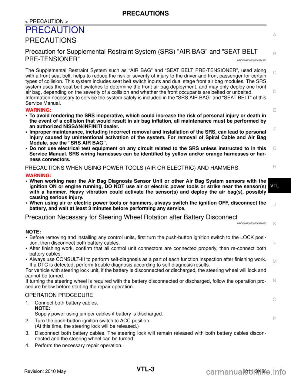
PRECAUTIONS
Precaution for Supplemental Restraint System (SRS) "AIR BAG" and "SEAT BELT
PRE-TENSIONER"
INFOID:0000000006376373
The Supplemental Restraint System such as “A IR BAG” and “SEAT BELT PRE-TENSIONER”, used along
with a front seat belt, helps to reduce the risk or severi ty of injury to the driver and front passenger for certain
types of collision. This system includes seat belt switch inputs and dual stage front air bag modules. The SRS
system uses the seat belt switches to determine the front air bag deployment, and may only deploy one front
air bag, depending on the severity of a collision and whether the front occupants are belted or unbelted.
Information necessary to service the system safely is included in the “SRS AIR BAG” and “SEAT BELT” of this
Service Manual.
WARNING:
• To avoid rendering the SRS inoper ative, which could increase the risk of personal injury or death in
the event of a collision that would result in air ba g inflation, all maintenance must be performed by
an authorized NISSAN/INFINITI dealer.
Improper maintenance, including in correct removal and installation of the SRS, can lead to personal
injury caused by unintentional act ivation of the system. For removal of Spiral Cable and Air Bag
Module, see the “SRS AIR BAG”.
Do not use electrical test equipm ent on any circuit related to the SRS unless instructed to in this
Service Manual. SRS wiring harnesses can be identi fied by yellow and/or orange harnesses or har-
ness connectors.
PRECAUTIONS WHEN USING POWER TOOLS (AIR OR ELECTRIC) AND HAMMERS
WARNING:
When working near the Air Bag Diagnosis Sensor Unit or other Air Bag System sensors with the
ignition ON or engine running, DO NOT use air or electric power tools or strike near the sensor(s)
with a hammer. Heavy vibration could activate the sensor(s) and deploy the air bag(s), possibly
causing serious injury.
When using air or electric power tools or hammers , always switch the ignition OFF, disconnect the
battery, and wait at least 3 minutes before performing any service.
Precaution Necessary for Steering Wh eel Rotation after Battery Disconnect
INFOID:0000000006376453
NOTE:
Before removing and installing any control units, first tu rn the push-button ignition switch to the LOCK posi-
tion, then disconnect both battery cables.
After finishing work, confirm that all control unit connectors are connected properly, then re-connect both
battery cables.
Always use CONSULT-III to perform self-diagnosis as a part of each function inspection after finishing work.
If a DTC is detected, perform trouble diagnos is according to self-diagnosis results.
For vehicle with steering lock unit, if the battery is disconnected or discharged, the steering wheel will lock and
cannot be turned.
If turning the steering wheel is required with the batte ry disconnected or discharged, follow the operation pro-
cedure below before starting the repair operation.
OPERATION PROCEDURE
1. Connect both battery cables. NOTE:
Supply power using jumper cables if battery is discharged.
2. Turn the push-button ignition switch to ACC position. (At this time, the steering lock will be released.)
3. Disconnect both battery cables. The steering lock wil l remain released with both battery cables discon-
nected and the steering wheel can be turned.
4. Perform the necessary repair operation.
Revision: 2010 May2011 QX56