2011 INFINITI QX56 ECU
[x] Cancel search: ECUPage 4561 of 5598

SE-102
< SYMPTOM DIAGNOSIS >
SQUEAK AND RATTLE TROUBLE DIAGNOSES
Most of these incidents can be repaired by adjusting, securing or insulating the item(s) or component(s) caus-
ing the noise.
SUNROOF/HEADLINING
Noises in the sunroof/headlining area c an often be traced to one of the following:
1. Sunroof lid, rail, linkage or seals making a rattle or light knocking noise
2. Sunvisor shaft shaking in the holder
3. Front or rear windshield touching headlining and squeaking
Again, pressing on the components to stop the noise while duplicating the conditions can isolate most of these
incidents. Repairs usually consist of insulating with felt cloth tape.
SEATS
When isolating seat noise it's important to note the position the seats in and the load placed on the seat when
the noise occurs. These conditions should be duplicated when verifying and isolating the cause of the noise.
Cause of seat noise include:
1. Headrest rods and holder
2. A squeak between the seat pad cushion and frame
3. The rear seatback lock and bracket
These noises can be isolated by moving or pressing on the suspected components while duplicating the con-
ditions under which the noise occurs.Most of these incidents can be repaired by repositioning the component
or applying urethane tape to the contact area.
UNDERHOOD
Some interior noise may be caused by components under the hood or on the engine wall. The noise is then
transmitted into the passenger compartment.
Causes of transmitted underhood noise include:
1. Any component mounted to the engine wall
2. Components that pass through the engine wall
3. Engine wall mounts and connectors
4. Loose radiator mounting pins
5. Hood bumpers out of adjustment
6. Hood striker out of adjustment
These noises can be difficult to isolate since they cannot be reached from the interior of the vehicle. The best
method is to secure, move or insulate one component at a time and test drive the \
vehicle. Also, engine RPM
or load can be changed to isolate the noise. Repairs can usually be made by moving, adjusting, securing, or
insulating the component causing the noise.
Revision: 2010 May2011 QX56
Page 4572 of 5598
FRONT SEATSE-113
< REMOVAL AND INSTALLATION >
C
DE
F
G H
I
K L
M A
B
SE
N
O P
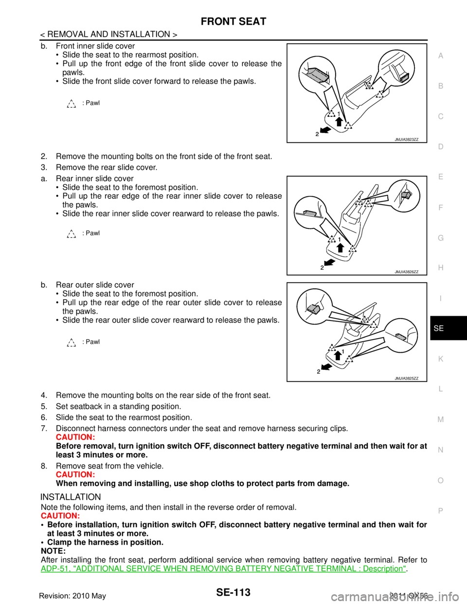
b. Front inner slide cover Slide the seat to the rearmost position.
Pull up the front edge of the front slide cover to release thepawls.
Slide the front slide cover forward to release the pawls.
2. Remove the mounting bolts on the front side of the front seat.
3. Remove the rear slide cover.
a. Rear inner slide cover Slide the seat to the foremost position.
Pull up the rear edge of the rear inner slide cover to releasethe pawls.
Slide the rear inner slide cover rearward to release the pawls.
b. Rear outer slide cover Slide the seat to the foremost position.
Pull up the rear edge of the rear outer slide cover to releasethe pawls.
Slide the rear outer slide cover rearward to release the pawls.
4. Remove the mounting bolts on t he rear side of the front seat.
5. Set seatback in a standing position.
6. Slide the seat to the rearmost position.
7. Disconnect harness connectors under the seat and remove harness securing clips. CAUTION:
Before removal, turn ignition sw itch OFF, disconnect battery negative terminal and then wait for at
least 3 minutes or more.
8. Remove seat from the vehicle. CAUTION:
When removing and installing, use shop cloths to protect parts from damage.
INSTALLATION
Note the following items, and then install in the reverse order of removal.
CAUTION:
Before installation, turn ignition switch OFF, disconnect battery ne gative terminal and then wait for
at least 3 minutes or more.
Clamp the harness in position.
NOTE:
After installing the front seat, perform additional serv ice when removing battery negative terminal. Refer to
ADP-51, "
ADDITIONAL SERVICE WHEN REMOVING BATTERY NEGATIVE TERMINAL : Description".
: Pawl
JMJIA3823ZZ
: Pawl
JMJIA3826ZZ
: Pawl
JMJIA3825ZZ
Revision: 2010 May2011 QX56
Page 4574 of 5598
FRONT SEATSE-115
< REMOVAL AND INSTALLATION >
C
DE
F
G H
I
K L
M A
B
SE
N
O P
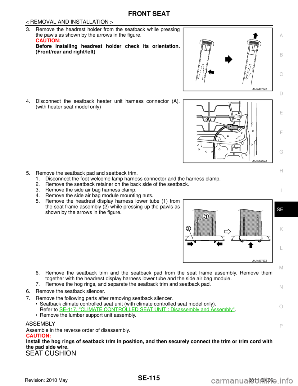
3. Remove the headrest holder from the seatback while pressing the pawls as shown by the arrows in the figure.
CAUTION:
Before installing headrest holder check its orientation.
(Front/rear and right/left)
4. Disconnect the seatback heater unit harness connector (A). (with heater seat model only)
5. Remove the seatback pad and seatback trim. 1. Disconnect the foot welcome lamp harness connector and the harness clamp.
2. Remove the seatback retainer on the back side of the seatback.
3. Remove the side air bag harness clamp.
4. Remove the side air bag module mounting nuts.
5. Remove the headrest display harness lower tube (1) from
the seat frame assembly (2) while pressing up the pawls as
shown by the arrows in the figure.
6. Remove the seatback trim and the seatback pad from the seat frame assembly. Remove them
together with the headrest display harness lower tube and the side air bag module.
7. Remove the hog rings, and separate the seatback trim and seatback pad.
6. Remove the seatback silencer.
7. Remove the following parts after removing seatback silencer. Seatback climate controlled seat unit (wit h climate controlled seat model only).
Refer to SE-117, "
CLIMATE CONTROLLED SEAT UNIT : Disassembly and Assembly".
Remove the lumber support unit assembly.
ASSEMBLY
Assemble in the reverse order of disassembly.
CAUTION:
Install the hog rings of seatback trim in position, and then securely connect the trim or trim cord with
the pad side wire.
SEAT CUSHION
JMJIA4073ZZ
JMJIA4326ZZ
JMJIA3976ZZ
Revision: 2010 May2011 QX56
Page 4576 of 5598
FRONT SEATSE-117
< REMOVAL AND INSTALLATION >
C
DE
F
G H
I
K L
M A
B
SE
N
O P
ASSEMBLY
Assemble in the reverse order of disassembly.
CAUTION:
Install the hog rings of seat cushion trim in positi on, and then securely connect the trim or trim cord
with the pad side wire.
CLIMATE CONTROLLED SEAT UNIT
CLIMATE CONTROLLED SEAT UNI T : Disassembly and AssemblyINFOID:0000000006217427
DISASSEMBLY
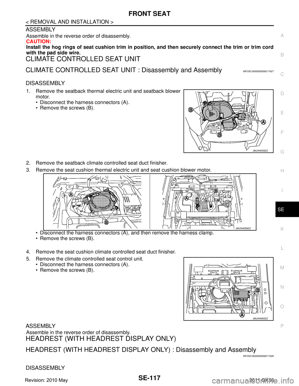
1. Remove the seatback thermal electric unit and seatback blower
motor.
Disconnect the harness connectors (A).
Remove the screws (B).
2. Remove the seatback climate controlled seat duct finisher.
3. Remove the seat cushion thermal electric unit and seat cushion blower motor.
Disconnect the harness connectors (A), and then remove the harness clamp.
Remove the screws (B).
4. Remove the seat cushion climat e controlled seat duct finisher.
5. Remove the climate controlled seat control unit. Disconnect the harness connectors (A).
Remove the screws (B).
ASSEMBLY
Assemble in the reverse order of disassembly.
HEADREST (WITH HEAD REST DISPLAY ONLY)
HEADREST (WITH HEADREST DISPLAY ONLY) : Disassembly and Assembly
INFOID:0000000006217428
DISASSEMBLY
JMJIA4058ZZ
JMJIA4059ZZ
JMJIA4060ZZ
Revision: 2010 May2011 QX56
Page 4589 of 5598
SE-130
< REMOVAL AND INSTALLATION >
SECOND SEAT
1. Remove the reclining device outer cover (outside) and reclining device outer cover (inside).
Refer to SE-130, "
SEAT CUSHION : Disassembly and Assembly".
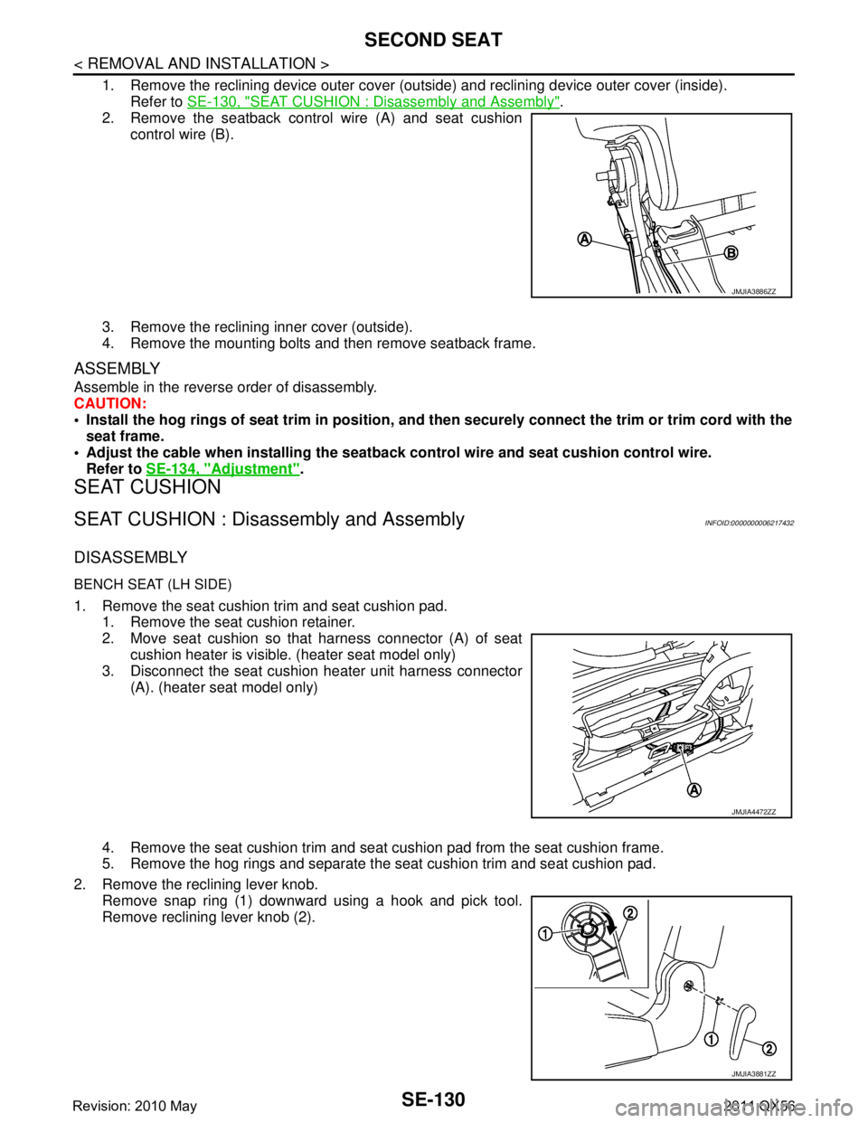
2. Remove the seatback control wire (A) and seat cushion
control wire (B).
3. Remove the reclining inner cover (outside).
4. Remove the mounting bolts and then remove seatback frame.
ASSEMBLY
Assemble in the reverse order of disassembly.
CAUTION:
Install the hog rings of seat trim in position, and then securely connect the trim or trim cord with the
seat frame.
Adjust the cable when installing the seatback control wire and seat cushion control wire.
Refer to SE-134, "
Adjustment".
SEAT CUSHION
SEAT CUSHION : Disa ssembly and AssemblyINFOID:0000000006217432
DISASSEMBLY
BENCH SEAT (LH SIDE)
1. Remove the seat cushion trim and seat cushion pad.
1. Remove the seat cushion retainer.
2. Move seat cushion so that harness connector (A) of seatcushion heater is visible. (heater seat model only)
3. Disconnect the seat cushion heater unit harness connector (A). (heater seat model only)
4. Remove the seat cushion trim and seat cushion pad from the seat cushion frame.
5. Remove the hog rings and separate the seat cushion trim and seat cushion pad.
2. Remove the reclining lever knob. Remove snap ring (1) downward using a hook and pick tool.
Remove reclining lever knob (2).
JMJIA3886ZZ
JMJIA4472ZZ
JMJIA3881ZZ
Revision: 2010 May2011 QX56
Page 4592 of 5598
SECOND SEATSE-133
< REMOVAL AND INSTALLATION >
C
DE
F
G H
I
K L
M A
B
SE
N
O P
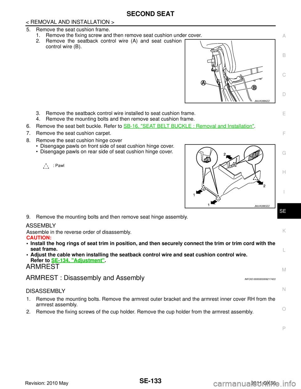
5. Remove the seat cushion frame. 1. Remove the fixing screw and then remove seat cushion under cover.
2. Remove the seatback control wire (A) and seat cushion control wire (B).
3. Remove the seatback control wire installed to seat cushion frame.
4. Remove the mounting bolts and then remove seat cushion frame.
6. Remove the seat belt buckle. Refer to SB-16, "
SEAT BELT BUCKLE : Removal and Installation".
7. Remove the seat cushion carpet.
8. Remove the seat cushion hinge cover Disengage pawls on front side of seat cushion hinge cover.
Disengage pawls on rear side of seat cushion hinge cover.
9. Remove the mounting bolts and then remove seat hinge assembly.
ASSEMBLY
Assemble in the reverse order of disassembly.
CAUTION:
Install the hog rings of seat trim in position, and then securely connect the trim or trim cord with the
seat frame.
Adjust the cable when installing the seatb ack control wire and seat cushion control wire.
Refer to SE-134, "
Adjustment".
ARMREST
ARMREST : Disassembly and AssemblyINFOID:0000000006217433
DISASSEMBLY
1. Remove the mounting bolts. Remove the armrest out er bracket and the armrest inner cover RH from the
armrest assembly.
2. Remove the fixing screws of the cup holder. Remove the cup holder from the armrest assembly.
JMJIA3886ZZ
: Pawl
JMJIA3883ZZ
Revision: 2010 May2011 QX56
Page 4599 of 5598
SE-140
< REMOVAL AND INSTALLATION >
THIRD SEAT
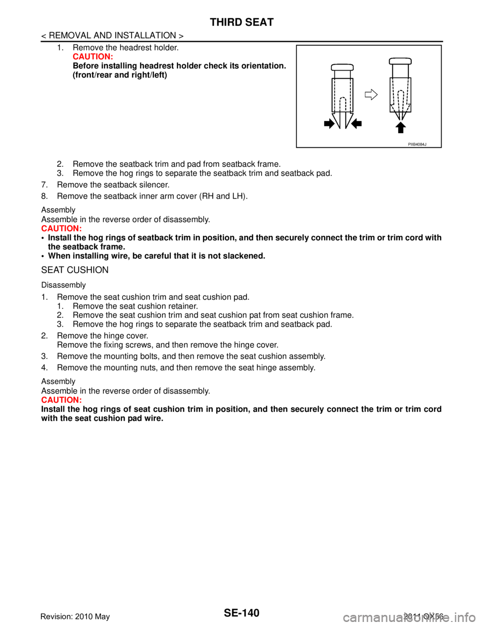
1. Remove the headrest holder.CAUTION:
Before installing headrest ho lder check its orientation.
(front/rear and right/left)
2. Remove the seatback trim and pad from seatback frame.
3. Remove the hog rings to separate the seatback trim and seatback pad.
7. Remove the seatback silencer.
8. Remove the seatback inner arm cover (RH and LH).
Assembly
Assemble in the reverse order of disassembly.
CAUTION:
Install the hog rings of seatback trim in position, and then securely connect the trim or trim cord with
the seatback frame.
When installing wire, be caref ul that it is not slackened.
SEAT CUSHION
Disassembly
1. Remove the seat cushion trim and seat cushion pad.
1. Remove the seat cushion retainer.
2. Remove the seat cushion trim and seat cushion pat from seat cushion frame.
3. Remove the hog rings to separate the seatback trim and seatback pad.
2. Remove the hinge cover. Remove the fixing screws, and then remove the hinge cover.
3. Remove the mounting bolts, and then remove the seat cushion assembly.
4. Remove the mounting nuts, and then remove the seat hinge assembly.
Assembly
Assemble in the reverse order of disassembly.
CAUTION:
Install the hog rings of seat cushio n trim in position, and then securely connect the trim or trim cord
with the seat cushion pad wire.
PIIB4084J
Revision: 2010 May2011 QX56
Page 4608 of 5598
SEC-1
BODY EXTERIOR, DOORS, ROOF & VEHICLE SECURITY
C
D
E
F
G H
I
J
L
M
SECTION SEC
A
B
SEC
N
O P
CONTENTS
SECURITY CONTROL SYSTEM
WITH INTELLIGE NT KEY SYSTEM
PRECAUTION ................ ...............................
5
PRECAUTIONS .............................................. .....5
Precaution for Supplemental Restraint System
(SRS) "AIR BAG" and "SEAT BELT PRE-TEN-
SIONER" ............................................................. ......
5
Precaution Necessary for Steering Wheel Rota-
tion after Battery Disconnect .....................................
5
Precaution for Procedure without Cowl Top Cover ......6
SYSTEM DESCRIPTION ..............................7
COMPONENT PARTS ................................... .....7
Component Parts Location .................................. ......7
Component Description .............................................8
A/T Shift Selector (Detention Switch) ........................8
BCM ..........................................................................8
ECM ..........................................................................9
IPDM E/R ..................................................................9
NATS Antenna Amp. .................................................9
TCM ..........................................................................9
Combination Meter ....................................................9
Door Switch ...............................................................9
Hood Switch ..............................................................9
Inside Key Antenna ...................................................9
Intelligent Key ............................................................9
Push-button Ignition Switch .....................................10
Remote Keyless Entry Receiver .............................10
Security Indicator Lamp ..........................................10
Starter Control Relay ...............................................10
Starter Relay ...........................................................10
Steering Lock Relay ................................................10
Steering Lock Unit ...................................................10
Stop Lamp Switch ...................................................10
Transmission Range Switch ....................................10
Vehicle Information Display .....................................11
SYSTEM .............................................................12
INTELLIGENT KEY SYSTEM/ENGINE START
FUNCTION ............................................................. ....
12
INTELLIGENT KEY SYSTEM/ENGINE START
FUNCTION : System Diagram ................................
12
INTELLIGENT KEY SYSTEM/ENGINE START
FUNCTION : System Description ............................
12
INFINITI VEHICLE IMMOBILIZER SYSTEM-NATS ....14
INFINITI VEHICLE IMMOBILIZER SYSTEM-
NATS : System Diagram .........................................
15
INFINITI VEHICLE IMMOBILIZER SYSTEM-
NATS : System Description .....................................
15
VEHICLE SECURITY SYSTEM .................................17
VEHICLE SECURITY SYSTEM : System Dia-
gram .................................................................... ....
17
VEHICLE SECURITY SYSTEM : System Descrip-
tion ...........................................................................
18
DIAGNOSIS SYSTEM (BCM) ...........................21
COMMON ITEM ..................................................... ....21
COMMON ITEM : CONSULT-III Function (BCM -
COMMON ITEM) .....................................................
21
INTELLIGENT KEY ................................................ ....22
INTELLIGENT KEY : CONSULT-III Function
(BCM - INTELLIGENT KEY) ....................................
22
THEFT ALM ........................................................... ....26
THEFT ALM : CONSULT-III Function (BCM -
THEFT) ................................................................ ....
26
IMMU ...................................................................... ....27
IMMU : CONSULT-III Function (BCM - IMMU) ........27
DIAGNOSIS SYSTEM (IPDM E/R) ...................28
CONSULT-III Function (IPDM E/R) .........................28
ECU DIAGNOSIS INFORMATION ..............30
ECM, IPDM E/R, BCM .......................................30
List of ECU Reference ......................................... ....30
Revision: 2010 May2011 QX56