2011 INFINITI QX56 bulb
[x] Cancel search: bulbPage 2854 of 5598
![INFINITI QX56 2011 Factory Service Manual
EXL-144
< REMOVAL AND INSTALLATION >[XENON TYPE]
LICENSE PLATE LAMP
3. Turn bulb socket (1) counterclockwise and unlock it.
4. Remove bulb (2) from socket.
JPLIA0930ZZ
Revision: 2010 May2011 QX56 INFINITI QX56 2011 Factory Service Manual
EXL-144
< REMOVAL AND INSTALLATION >[XENON TYPE]
LICENSE PLATE LAMP
3. Turn bulb socket (1) counterclockwise and unlock it.
4. Remove bulb (2) from socket.
JPLIA0930ZZ
Revision: 2010 May2011 QX56](/manual-img/42/57033/w960_57033-2853.png)
EXL-144
< REMOVAL AND INSTALLATION >[XENON TYPE]
LICENSE PLATE LAMP
3. Turn bulb socket (1) counterclockwise and unlock it.
4. Remove bulb (2) from socket.
JPLIA0930ZZ
Revision: 2010 May2011 QX56
Page 2855 of 5598
![INFINITI QX56 2011 Factory Service Manual
SERVICE DATA AND SPECIFICATIONS (SDS)
EXL-145
< SERVICE DATA AND SPECIFICATIONS (SDS) [XENON TYPE]
C
D
E
F
G H
I
J
K
M A
B
EXL
N
O P
SERVICE DATA AND SPECIFICATIONS (SDS)
SERVICE DATA AND SPECIFICAT INFINITI QX56 2011 Factory Service Manual
SERVICE DATA AND SPECIFICATIONS (SDS)
EXL-145
< SERVICE DATA AND SPECIFICATIONS (SDS) [XENON TYPE]
C
D
E
F
G H
I
J
K
M A
B
EXL
N
O P
SERVICE DATA AND SPECIFICATIONS (SDS)
SERVICE DATA AND SPECIFICAT](/manual-img/42/57033/w960_57033-2854.png)
SERVICE DATA AND SPECIFICATIONS (SDS)
EXL-145
< SERVICE DATA AND SPECIFICATIONS (SDS) [XENON TYPE]
C
D
E
F
G H
I
J
K
M A
B
EXL
N
O P
SERVICE DATA AND SPECIFICATIONS (SDS)
SERVICE DATA AND SPECIFICATIONS (SDS)
Bulb SpecificationsINFOID:0000000006369512
Item Type Wattage (W)
Front combination lamp Headlamp (HI/LO) D2S (Xenon) 35
Front turn signal lamp WY21W (Amber) 21
Parking lamp W5W 5
Front fog lamp H8 35
Side turn signal lamp Replace as an assembly because it cannot be disassembled.
Rear combination lamp Stop lamp/Tail lamp LED —
Rear turn signal lamp WY21W 21
Back-up lamp W16W 16
Tail lamp W5W 5
License plate lamp W5W 5
High-mounted stop lamp LED —
Revision: 2010 May2011 QX56
Page 2990 of 5598

GI-26
< PRECAUTION >
PRECAUTIONS
PRECAUTION
PRECAUTIONS
DescriptionINFOID:0000000006280865
Observe the following precautions to ensure safe and proper servicing. These precautions are not
described in each individual section.
Precaution for Supplemental Restraint S ystem (SRS) "AIR BAG" and "SEAT BELT
PRE-TENSIONER"
INFOID:0000000006280866
The Supplemental Restraint System such as “A IR BAG” and “SEAT BELT PRE-TENSIONER”, used along
with a front seat belt, helps to reduce the risk or severi ty of injury to the driver and front passenger for certain
types of collision. This system includes seat belt switch inputs and dual stage front air bag modules. The SRS
system uses the seat belt switches to determine the front air bag deployment, and may only deploy one front
air bag, depending on the severity of a collision and w hether the front occupants are belted or unbelted.
Information necessary to service the system safely is included in the “SRS AIR BAG” and “SEAT BELT” of this
Service Manual.
WARNING:
To avoid rendering the SRS inopera tive, which could increase the risk of personal injury or death in
the event of a collision that would result in air bag inflation, all maintenance must be performed by
an authorized NISS AN/INFINITI dealer.
Improper maintenance, including in correct removal and installation of the SRS, can lead to personal
injury caused by unintent ional activation of the system. For re moval of Spiral Cable and Air Bag
Module, see the “SRS AIR BAG”.
Do not use electrical test equipmen t on any circuit related to the SRS unless instructed to in this
Service Manual. SRS wiring harnesses can be identi fied by yellow and/or orange harnesses or har-
ness connectors.
PRECAUTIONS WHEN USING POWER TOOLS (AIR OR ELECTRIC) AND HAMMERS
WARNING:
When working near the Air Bag Diagnosis Sensor Unit or other Air Bag System sensors with the
ignition ON or engine running, DO NOT use air or electric power tools or strike near the sensor(s)
with a hammer. Heavy vibration could activate the sensor(s) and deploy the air bag(s), possibly
causing serious injury.
When using air or electric power tools or hammers , always switch the ignition OFF, disconnect the
battery, and wait at least 3 minu tes before performing any service.
Precautions For Xenon Headlamp ServiceINFOID:0000000006280867
WARNING:
Comply with the following warnings to prevent any serious accident.
Disconnect the battery cable (negative terminal) or the power supply fuse before installing, remov-
ing, or touching the xenon headlamp (bulb included). The xenon headlamp contains high-voltage
generated parts.
Never work with wet hands.
Check the xenon headlamp ON-OFF status after assembling it to the vehicle. Never turn the xenon
headlamp ON in other conditions. Connect th e power supply to the vehicle-side connector.
(Turning it ON outside the lamp case m ay cause fire or visual impairments.)
Never touch the bulb glass immediately after turning it OFF. It is extremely hot.
CAUTION:
Comply with the following cautions to prevent any error and malfunction.
Install the xenon bulb securely. (Ins ufficient bulb socket installation may melt the bulb, the connec-
tor, the housing, etc. by high-v oltage leakage or corona discharge.)
Never perform HID circuit in spection with a tester.
Never touch the xenon bulb glass with ha nds. Never put oil and grease on it.
Dispose of the used xenon bulb after packing it in thick vinyl without breaking it.
Never wipe out dirt and cont amination with organic solven t (thinner, gasoline, etc.).
Revision: 2010 May2011 QX56
Page 3010 of 5598

GI-46
< BASIC INSPECTION >
SERVICE INFORMATION FOR ELECTRICAL INCIDENT
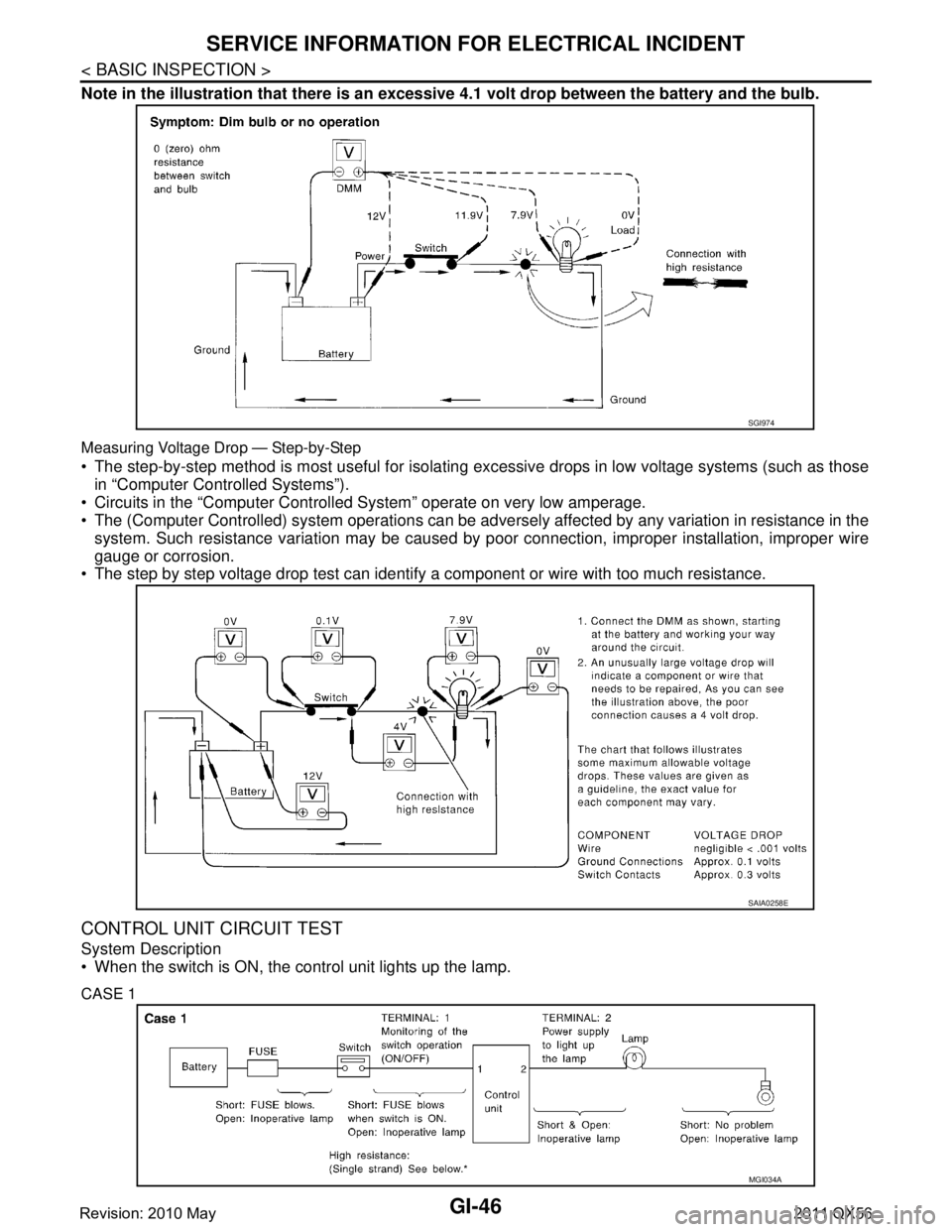
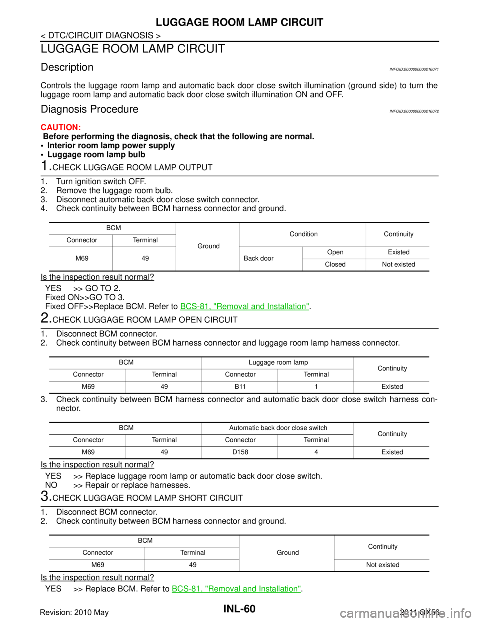
Note in the illustration that there is an excessive 4.1 volt drop between the battery and the bulb.
Measuring Voltage Drop — Step-by-Step
The step-by-step method is most useful for isolating excessive drops in low voltage systems (such as those
in “Computer Controlled Systems”).
Circuits in the “Computer Controlled System” operate on very low amperage.
The (Computer Controlled) system oper ations can be adversely affected by any variation in resistance in the
system. Such resistance variation may be caused by poor connection, improper installation, improper wire
gauge or corrosion.
The step by step voltage drop test can identify a component or wire with too much resistance.
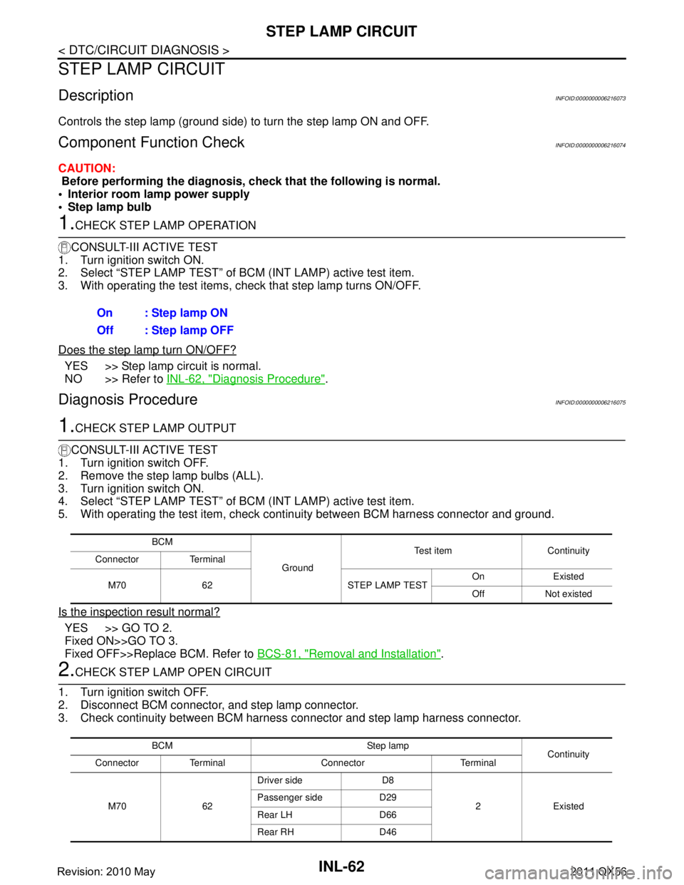
CONTROL UNIT CIRCUIT TEST
System Description
When the switch is ON, the control unit lights up the lamp.
CASE 1
SGI974
SAIA0258E
MGI034A
Revision: 2010 May2011 QX56
Page 3269 of 5598

INL-2
LUGGAGE ROOM LAMP CIRCUIT ..................60
Description ........................................................... ...60
Diagnosis Procedure ..............................................60
STEP LAMP CIRCUIT .......................................62
Description ........................................................... ...62
Component Function Check ...................................62
Diagnosis Procedure ..............................................62
PUDDLE LAMP CIRCUIT ..................................64
Description ........................................................... ...64
Diagnosis Procedure ..............................................64
PUSH-BUTTON IGNITION SWITCH ILLUMI-
NATION CIRCUIT ..............................................
65
Component Function Check ................................ ...65
Diagnosis Procedure ..............................................65
SYMPTOM DIAGNOSIS .............................67
INTERIOR LIGHTING SYSTEM SYMPTOMS ...67
Symptom Table ................................................... ...67
REMOVAL AND INSTALLATION ...............68
MAP LAMP ..................................................... ...68
Exploded View ..................................................... ...68
Removal and Installation ........................................68
Replacement ..........................................................68
VANITY MIRROR LAMP ...................................69
Exploded View ..................................................... ...69
Replacement ..........................................................69
GLOVE BOX LAMP ...........................................70
Exploded View ..................................................... ...70
Replacement ..........................................................70
FOOT LAMP ......................................................71
DRIVER SIDE ......................................................... ...71
DRIVER SIDE : Exploded View ..............................71
DRIVER SIDE : Replacement ................................71
PASSENGER SIDE ...................................................71
PASSENGER SIDE : Exploded View .....................71
PASSENGER SIDE : Replac ement ........................72
REAR FOOT LAMP ................................................ ...72
REAR FOOT LAMP : Exploded View .....................72
REAR FOOT LAMP : Removal and Installation ......72
STEP LAMP .......................................................74
Exploded View ..................................................... ...74
Removal and Installation .........................................74
Replacement ...........................................................74
MOOD LAMP .....................................................75
FRONT DOOR ARMREST ..................................... ...75
FRONT DOOR ARMREST : Exploded View ..........75
FRONT DOOR ARMREST : Replacement .............75
REAR DOOR ARMREST ....................................... ...75
REAR DOOR ARMREST : Exploded View .............75
REAR DOOR ARMREST : Replacement ...............76
PERSONAL LAMP ............................................77
Exploded View ..................................................... ...77
Removal and Installation .........................................77
Replacement ...........................................................78
PUDDLE LAMP .............................................. ...79
Exploded View ..................................................... ...79
Removal and Installation .........................................79
LUGGAGE ROOM LAMP ..................................81
Exploded View ..................................................... ...81
Removal and Installation .........................................81
Replacement ...........................................................81
SERVICE DATA AND SPECIFICATIONS
(SDS) .......... ................................................
82
SERVICE DATA AND SPECIFICATIONS
(SDS) .............................................................. ...
82
Bulb Specifications ............................................... ...82
Revision: 2010 May2011 QX56
Page 3325 of 5598

INL-58
< DTC/CIRCUIT DIAGNOSIS >
INTERIOR ROOM LAMP CONTROL CIRCUIT
INTERIOR ROOM LAMP CONTROL CIRCUIT
DescriptionINFOID:0000000006216068
Controls each interior room lamp (ground side) by PWM signal.
NOTE:
PWM signal control period is approximately 250 Hz (in the gradual brightening/dimming).
Component Function CheckINFOID:0000000006216069
CAUTION:
Before performing the diagnosis, check that the following are normal.
Interior room lamp power supply
Map lamp bulb
Personal lamp bulb
Foot lamp bulb
1.CHECK INTERIOR ROOM LAMP CONTROL FUNCTION
CONSULT-III ACTIVE TEST
1. Switch the map lamp switch and personal lamp switch to DOOR.
2. Turn ignition switch ON.
3. Select “INT LAMP” of BCM (INT LAMP) active test item.
4. With operating the test items, c heck that each interior room lamp turns ON/OFF (gradual brightening/dim-
ming).
Does the interior room lamp turns ON/OFF (gradual brightening/dimming)?
YES >> Interior room lamp control circuit is normal.
NO >> Refer to INL-58, "
Diagnosis Procedure".
Diagnosis ProcedureINFOID:0000000006216070
1.CHECK INTERIOR ROOM LAMP CONTROL OUTPUT
CONSULT-III ACTIVE TEST
1. Switch the map lamp switch and personal lamp switch to DOOR.
2. Turn ignition switch OFF.
3. Remove all the bulbs of map lamp, foot lamp and personal lamp.
4. Turn ignition switch ON.
5. Select “INT LAMP” of BCM (INT LAMP) active test item.
6. With operating the test item, check c ontinuity between BCM harness connector and ground.
Is the inspection result normal?
YES >> GO TO 2.
Fixed ON>>GO TO 3.
Fixed OFF>>Replace BCM. Refer to BCS-81, "
Removal and Installation".
2.CHECK INTERIOR ROOM LAMP CONTROL OPEN CIRCUIT
1. Turn ignition switch OFF.
2. Disconnect BCM connector, map lamp connector, personal lamp connector and foot lamp connector.
3. Check continuity between BCM harness connector and foot lamp harness connector.
On : Interior room lamp gradual brightening
Off : Interior room lamp gradual dimming
BCM
Ground Test item Continuity
Connector Terminal
M70 63 INT LAMP On Existed
Off Not existed
Revision: 2010 May2011 QX56
Page 3327 of 5598

INL-60
< DTC/CIRCUIT DIAGNOSIS >
LUGGAGE ROOM LAMP CIRCUIT
LUGGAGE ROOM LAMP CIRCUIT
DescriptionINFOID:0000000006216071
Controls the luggage room lamp and automatic back door close switch illumination (ground side) to turn the
luggage room lamp and automatic back door close switch illumination ON and OFF.
Diagnosis ProcedureINFOID:0000000006216072
CAUTION:
Before performing the diagnosis, check that the following are normal.
Interior room lamp power supply
Luggage room lamp bulb
1.CHECK LUGGAGE ROOM LAMP OUTPUT
1. Turn ignition switch OFF.
2. Remove the luggage room bulb.
3. Disconnect automatic back door close switch connector.
4. Check continuity between BCM harness connector and ground.
Is the inspection result normal?
YES >> GO TO 2.
Fixed ON>>GO TO 3.
Fixed OFF>>Replace BCM. Refer to BCS-81, "
Removal and Installation".
2.CHECK LUGGAGE ROOM LAMP OPEN CIRCUIT
1. Disconnect BCM connector.
2. Check continuity between BCM harness c onnector and luggage room lamp harness connector.
3. Check continuity between BCM harness connector and automatic back door close switch harness con-
nector.
Is the inspection result normal?
YES >> Replace luggage room lamp or automatic back door close switch.
NO >> Repair or replace harnesses.
3.CHECK LUGGAGE ROOM LAMP SHORT CIRCUIT
1. Disconnect BCM connector.
2. Check continuity between BCM harness connector and ground.
Is the inspection result normal?
YES >> Replace BCM. Refer to BCS-81, "Removal and Installation".
BCM
Ground Condition Continuity
Connector Terminal
M69 49 Back door Open Existed
Closed Not existed
BCM Luggage room lamp Continuity
Connector Terminal Connector Terminal
M69 49 B11 1 Existed
BCM Automatic back door close switch Continuity
Connector Terminal Connector Terminal
M69 49 D158 4 Existed
BCM GroundContinuity
Connector Terminal
M69 49 Not existed
Revision: 2010 May2011 QX56
Page 3329 of 5598

INL-62
< DTC/CIRCUIT DIAGNOSIS >
STEP LAMP CIRCUIT
STEP LAMP CIRCUIT
DescriptionINFOID:0000000006216073
Controls the step lamp (ground side) to turn the step lamp ON and OFF.
Component Function CheckINFOID:0000000006216074
CAUTION:
Before performing the diagnosis, check that the following is normal.
Interior room lamp power supply
Step lamp bulb
1.CHECK STEP LAMP OPERATION
CONSULT-III ACTIVE TEST
1. Turn ignition switch ON.
2. Select “STEP LAMP TEST” of BCM (INT LAMP) active test item.
3. With operating the test items, c heck that step lamp turns ON/OFF.
Does the step lamp turn ON/OFF?
YES >> Step lamp circuit is normal.
NO >> Refer to INL-62, "
Diagnosis Procedure".
Diagnosis ProcedureINFOID:0000000006216075
1.CHECK STEP LAMP OUTPUT
CONSULT-III ACTIVE TEST
1. Turn ignition switch OFF.
2. Remove the step lamp bulbs (ALL).
3. Turn ignition switch ON.
4. Select “STEP LAMP TEST” of BCM (INT LAMP) active test item.
5. With operating the test item, check c ontinuity between BCM harness connector and ground.
Is the inspection result normal?
YES >> GO TO 2.
Fixed ON>>GO TO 3.
Fixed OFF>>Replace BCM. Refer to BCS-81, "
Removal and Installation".
2.CHECK STEP LAMP OPEN CIRCUIT
1. Turn ignition switch OFF.
2. Disconnect BCM connector, and step lamp connector.
3. Check continuity between BCM harness connector and step lamp harness connector.
On : Step lamp ON
Off : Step lamp OFF
BCM
Ground Test item Continuity
Connector Terminal
M70 62 STEP LAMP TEST On Existed
Off Not existed
BCM Step lamp Continuity
Connector Terminal Connector Terminal
M70 62 Driver side D8
2 Existed
Passenger side D29
Rear LH D66
Rear RH D46
Revision: 2010 May2011 QX56