2011 INFINITI QX56 oil
[x] Cancel search: oilPage 3870 of 5598
![INFINITI QX56 2011 Factory Service Manual
PCS
B2098 IGNITION RELAY ON STUCKPCS-29
< DTC/CIRCUIT DIAGNOSIS > [IPDM E/R]
C
D
E
F
G H
I
J
K L
B A
O P
N
B2098 IGNITION RELAY ON STUCK
DescriptionINFOID:0000000006220179
IPDM E/R operates the ign INFINITI QX56 2011 Factory Service Manual
PCS
B2098 IGNITION RELAY ON STUCKPCS-29
< DTC/CIRCUIT DIAGNOSIS > [IPDM E/R]
C
D
E
F
G H
I
J
K L
B A
O P
N
B2098 IGNITION RELAY ON STUCK
DescriptionINFOID:0000000006220179
IPDM E/R operates the ign](/manual-img/42/57033/w960_57033-3869.png)
PCS
B2098 IGNITION RELAY ON STUCKPCS-29
< DTC/CIRCUIT DIAGNOSIS > [IPDM E/R]
C
D
E
F
G H
I
J
K L
B A
O P
N
B2098 IGNITION RELAY ON STUCK
DescriptionINFOID:0000000006220179
IPDM E/R operates the ignition relay when it receives
an ignition switch ON signal from BCM via CAN com-
munication.
Turn the ignition relay OFF by pressing the push-butt on ignition switch once when the vehicle speed is 4 km/
h (2.5 MPH) or less.
Turn the ignition relay OFF with the following operat ion when the vehicle speed is more than 4 km/h (2.5
MPH) or when an abnormal condition occurs in CAN communication from the combination meter (Emer-
gency OFF)
- Press and hold the push-button ignition switch for 2 seconds or more.
- Press the push-button ignition switch 3 times within 1.5 seconds.
NOTE:
The ignition relay does not turn ON for 3 seconds af ter emergency OFF even if the push-button ignition switch
is pressed.
DTC LogicINFOID:0000000006220180
DTC DETECTION LOGIC
Diagnosis ProcedureINFOID:0000000006220181
1.PERFORM SELF DIAGNOSIS
1. Turn the ignition switch ON.
2. Erase “Self Diagnostic Result” of IPDM E/R.
3. Turn the ignition switch OFF, and wait for 1 second or more.
4. Turn the ignition switch ON. Check “Self Diagnostic Result” again.
Is DTC
“B2098” displayed?
YES >> Replace IPDM E/R. Refer to PCS-32, "Removal and Installation".
NO >> Refer to GI-40, "
Intermittent Incident".
DTCCONSULT-III dis-
play description DTC Detection Condit
ion Possible causes
B2098 IGN RELAY ON The ignition relay ON is detected for 1 second at ignition switch OFF
(CPU monitors the status at the contact and excitation coil circuits
of the ignition relay inside it) Ignition relay malfunction
Revision: 2010 May2011 QX56
Page 3871 of 5598
![INFINITI QX56 2011 Factory Service Manual
PCS-30
< DTC/CIRCUIT DIAGNOSIS >[IPDM E/R]
B2099 IGNITION RELAY OFF STUCK
B2099 IGNITION RELAY OFF STUCK
DescriptionINFOID:0000000006220182
IPDM E/R operates the ignition relay when it receives
an INFINITI QX56 2011 Factory Service Manual
PCS-30
< DTC/CIRCUIT DIAGNOSIS >[IPDM E/R]
B2099 IGNITION RELAY OFF STUCK
B2099 IGNITION RELAY OFF STUCK
DescriptionINFOID:0000000006220182
IPDM E/R operates the ignition relay when it receives
an](/manual-img/42/57033/w960_57033-3870.png)
PCS-30
< DTC/CIRCUIT DIAGNOSIS >[IPDM E/R]
B2099 IGNITION RELAY OFF STUCK
B2099 IGNITION RELAY OFF STUCK
DescriptionINFOID:0000000006220182
IPDM E/R operates the ignition relay when it receives
an ignition switch ON signal from BCM via CAN com-
munication.
Turn the ignition relay OFF by pressing the push-butt on ignition switch once when the vehicle speed is 4 km/
h (2.5 MPH) or less.
Turn the ignition relay OFF with the following operati on when the vehicle speed is more than 4 km/h (2.5
MPH) or when an abnormal condition occurs in CAN communication from the combination meter (Emer-
gency OFF)
- Press and hold the push-button ignition switch for 2 seconds or more.
- Press the push-button ignition switch 3 times within 1.5 seconds.
NOTE:
The ignition relay does not turn ON for 3 seconds af ter emergency OFF even if the push-button ignition switch
is pressed.
DTC LogicINFOID:0000000006220183
DTC DETECTION LOGIC
NOTE:
When IPDM E/R power supply voltage is low (Approx. 7 - 8 V for about 1 second), the “DTC: B2099” may be detected.
Diagnosis ProcedureINFOID:0000000006220184
1.PERFORM SELF DIAGNOSIS
1. Turn the ignition switch ON.
2. Erase “Self Diagnostic Result”.
3. Turn the ignition switch OFF.
4. Turn the ignition switch ON. Check “Self Diagnostic Result” again.
Is DTC
“B2099” displayed?
YES >> Replace IPDM E/R. Refer to PCS-32, "Removal and Installation".
NO >> Refer to GI-40, "
Intermittent Incident".
DTCCONSULT-III dis-
play description DTC Detection Condit
ion Possible causes
B2099 IGN RELAY OFF The ignition relay OFF is detected for 1 second at ignition switch ON
(CPU monitors the status at the contact and excitation coil circuits of
the ignition relay inside it) Ignition relay malfunction
Revision: 2010 May2011 QX56
Page 4204 of 5598

RAX-8
< REMOVAL AND INSTALLATION >
REAR WHEEL HUB AND HOUSING
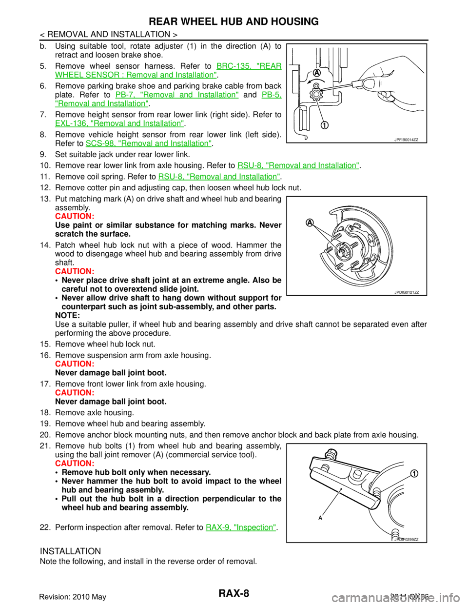
b. Using suitable tool, rotate adjuster (1) in the direction (A) toretract and loosen brake shoe.
5. Remove wheel sensor harness. Refer to BRC-135, "
REAR
WHEEL SENSOR : Removal and Installation".
6. Remove parking brake shoe and parking brake cable from back plate. Refer to PB-7, "
Removal and Installation" and PB-5,
"Removal and Installation".
7. Remove height sensor from rear lower link (right side). Refer to EXL-136, "
Removal and Installation".
8. Remove vehicle height sensor from rear lower link (left side). Refer to SCS-98, "
Removal and Installation".
9. Set suitable jack under rear lower link.
10. Remove rear lower link from axle housing. Refer to RSU-8, "
Removal and Installation".
11. Remove coil spring. Refer to RSU-8, "
Removal and Installation".
12. Remove cotter pin and adjusting cap, then loosen wheel hub lock nut.
13. Put matching mark (A) on drive shaft and wheel hub and bearing assembly.
CAUTION:
Use paint or similar substance for matching marks. Never
scratch the surface.
14. Patch wheel hub lock nut with a piece of wood. Hammer the wood to disengage wheel hub and bearing assembly from drive
shaft.
CAUTION:
Never place drive shaft joint at an extreme angle. Also be
careful not to over extend slide joint.
Never allow drive shaft to ha ng down without support for
counterpart such as joint sub-assembly, and other parts.
NOTE:
Use a suitable puller, if wheel hub and bearing assembly and drive shaft cannot be separated even after
performing the above procedure.
15. Remove wheel hub lock nut.
16. Remove suspension arm from axle housing. CAUTION:
Never damage ball joint boot.
17. Remove front lower link from axle housing. CAUTION:
Never damage ball joint boot.
18. Remove axle housing.
19. Remove wheel hub and bearing assembly.
20. Remove anchor block mounting nuts, and then remove anchor block and back plate from axle housing.
21. Remove hub bolts (1) from wheel hub and bearing assembly, using the ball joint remover (A) (commercial service tool).
CAUTION:
Remove hub bolt only when necessary.
Never hammer the hub bolt to avoid impact to the wheel
hub and bearing assembly.
Pull out the hub bolt in a direction perpendicular to the wheel hub and bearing assembly.
22. Perform inspection after removal. Refer to RAX-9, "
Inspection".
INSTALLATION
Note the following, and install in the reverse order of removal.
JPFIB0014ZZ
JPDIG0121ZZ
JPDIF0299ZZ
Revision: 2010 May2011 QX56
Page 4207 of 5598

REAR DRIVE SHAFTRAX-11
< REMOVAL AND INSTALLATION >
CEF
G H
I
J
K L
M A
B
RAX
N
O P
REAR DRIVE SHAFT
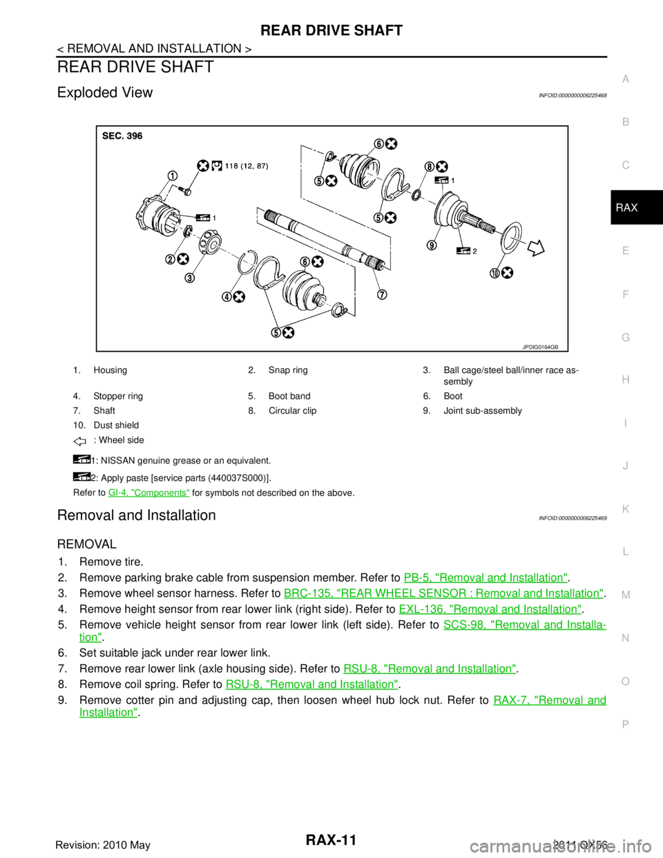
Exploded ViewINFOID:0000000006225468
Removal and InstallationINFOID:0000000006225469
REMOVAL
1. Remove tire.
2. Remove parking brake cable from suspension member. Refer to PB-5, "
Removal and Installation".
3. Remove wheel sensor harness. Refer to BRC-135, "
REAR WHEEL SENSOR : Removal and Installation".
4. Remove height sensor from rear lower link (right side). Refer to EXL-136, "
Removal and Installation".
5. Remove vehicle height sensor from rear lower link (left side). Refer to SCS-98, "
Removal and Installa-
tion".
6. Set suitable jack under rear lower link.
7. Remove rear lower link (axle housing side). Refer to RSU-8, "
Removal and Installation".
8. Remove coil spring. Refer to RSU-8, "
Removal and Installation".
9. Remove cotter pin and adjusting cap, then loosen wheel hub lock nut. Refer to RAX-7, "
Removal and
Installation".
1. Housing 2. Snap ring 3. Ball cage/steel ball/inner race as-
sembly
4. Stopper ring 5. Boot band 6. Boot
7. Shaft 8. Circular clip 9. Joint sub-assembly
10. Dust shield : Wheel side
1: NISSAN genuine grease or an equivalent.
2: Apply paste [service parts (440037S000)].
Refer to GI-4, "
Components" for symbols not described on the above.
JPDIG0164GB
Revision: 2010 May2011 QX56
Page 4256 of 5598

RSU-1
SUSPENSION
C
DF
G H
I
J
K L
M
SECTION RSU
A
B
RSU
N
O PCONTENTS
REAR SUSPENSION
PRECAUTION ................ ...............................2
PRECAUTIONS .............................................. .....2
Precautions for Suspension ................................ ......2
PREPARATION ............................................3
PREPARATION .............................................. .....3
Special Service Tools .......................................... ......3
Commercial Service Tools ........................................3
SYMPTOM DIAGNOSIS ...............................4
NOISE, VIBRATION AND HARSHNESS
(NVH) TROUBLESHOOTING ........................ .....
4
NVH Troubleshooting Chart ................................ ......4
PERIODIC MAINTENANCE ..........................5
REAR SUSPENSION ASSEMBLY ................ .....5
Inspection ............................................................ ......5
WHEEL ALIGNMENT ..........................................6
Inspection ............................................................ ......6
Adjustment ................................................................6
REMOVAL AND INSTALLATION ................8
REAR LOWER LINK & COIL SPRING .......... .....8
Exploded View .................................................... ......8
Removal and Installation ...........................................8
Inspection ..................................................................9
REAR SHOCK ABSORBER ..............................10
Exploded View .................................................... ....10
Removal and Installation ..................................... ....10
Inspection and Adjustment ......................................11
Disposal ...................................................................12
SUSPENSION ARM ..........................................13
Exploded View .........................................................13
Removal and Installation .........................................13
Inspection and Adjustment ......................................13
FRONT LOWER LINK .......................................15
Exploded View .........................................................15
Removal and Installation .........................................15
Inspection ................................................................15
REAR STABILIZER ..........................................17
Exploded View .........................................................17
Removal and Installation .........................................17
Inspection ................................................................17
UNIT REMOVAL AND INSTALLATION ......18
REAR SUSPENSION MEMBER .......................18
Exploded View ..................................................... ....18
Removal and Installation .........................................18
Inspection and Adjustment ......................................19
SERVICE DATA AND SPECIFICATIONS
(SDS) ............... .............................................
20
SERVICE DATA AND SPECIFICATIONS
(SDS) .................................................................
20
Wheel Alignment ................................................. ....20
Ball Joint ..................................................................20
Wheel Height ...........................................................20
Revision: 2010 May2011 QX56
Page 4257 of 5598

RSU-2
< PRECAUTION >
PRECAUTIONS
PRECAUTION
PRECAUTIONS
Precautions for SuspensionINFOID:0000000006225656
• When installing rubber bushings, the final tightening must be carried out under unladen conditions with tires
on ground. Spilled oil might shorten the life of rubber bushings. Be sure to wipe off any spilled oil.
- Unladen conditions mean that fuel, engine coolant and l ubricant are full. Spare tire, jack, hand tools and
mats are in designated positions.
After servicing suspension parts, be sure to check wheel alignment.
Self-lock nuts are not reusable. Always use new ones when installing. Since new self-lock nuts are pre-oiled,
tighten as they are.
Revision: 2010 May2011 QX56
Page 4258 of 5598

PREPARATIONRSU-3
< PREPARATION >
C
DF
G H
I
J
K L
M A
B
RSU
N
O P
PREPARATION
PREPARATION
Special Service ToolsINFOID:0000000006225657
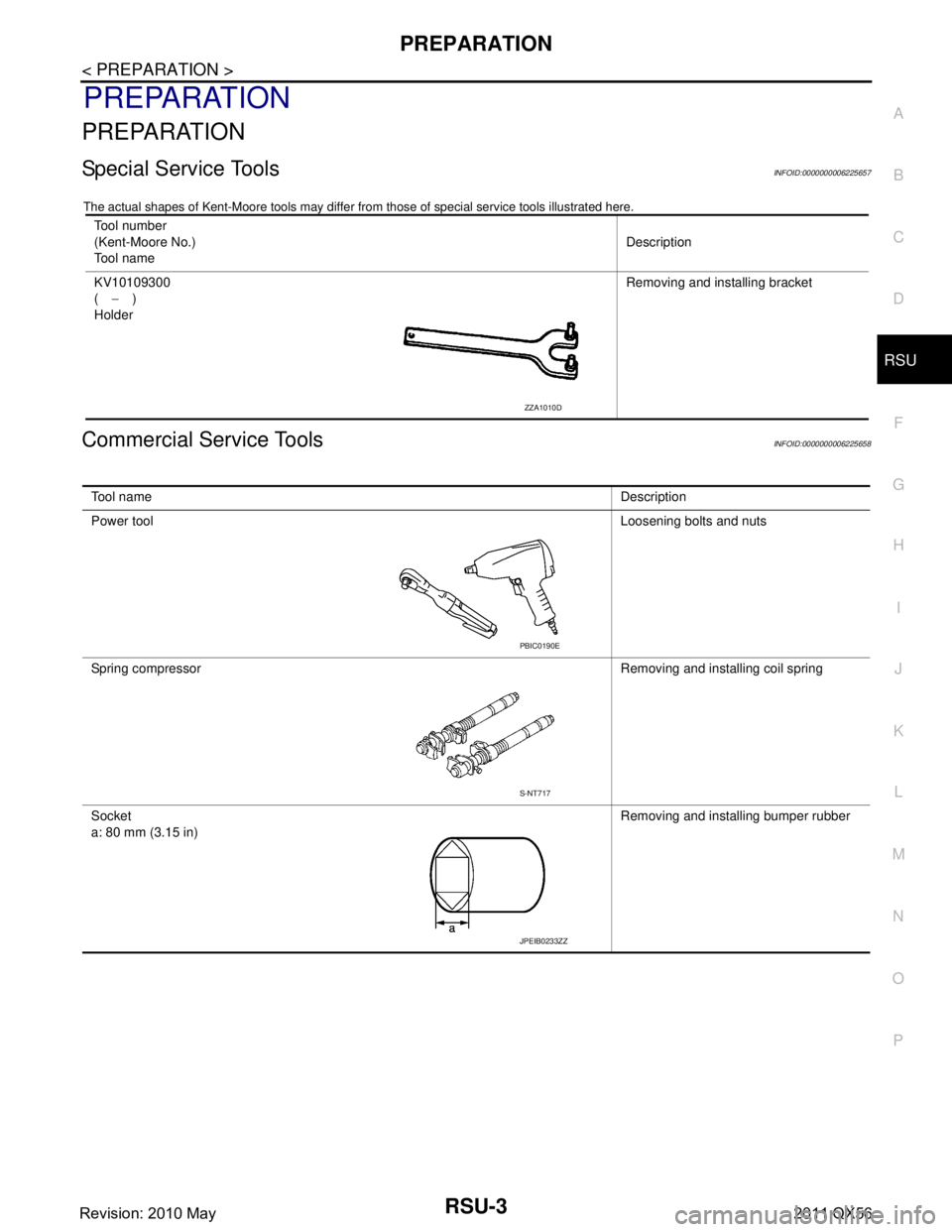
The actual shapes of Kent-Moore t ools may differ from those of special service tools illustrated here.
Commercial Service ToolsINFOID:0000000006225658
Tool number
(Kent-Moore No.)
Tool name Description
KV10109300
( − )
Holder Removing and installing bracket
ZZA1010D
Tool name
Description
Power tool Loosening bolts and nuts
Spring compressor Removing and installing coil spring
Socket
a: 80 mm (3.15 in) Removing and installing bumper rubber
PBIC0190E
S-NT717
JPEIB0233ZZ
Revision: 2010 May2011 QX56
Page 4260 of 5598

REAR SUSPENSION ASSEMBLYRSU-5
< PERIODIC MAINTENANCE >
C
DF
G H
I
J
K L
M A
B
RSU
N
O P
PERIODIC MAINTENANCE
REAR SUSPENSION ASSEMBLY
InspectionINFOID:0000000006225660
MOUNTING INSPECTION
Check the mounting conditions (looseness, backlash) of each component and component conditions (wear,
damage) are normal.
BALL JOINT AXIAL END PLAY
Measure axial end play by placing and moving up/down with an iron bar or equivalent between suspension
arm or front lower link and axle assembly.
CAUTION:
• Never depress brake pedal when measuring.
Never perform with tires on level ground.
Be careful not to damage ball joint boot.
SHOCK ABSORBER
Check for oil leakage and damage. Replace it if necessary. Axial end play : Refer to
RSU-20, "
Ball Joint".
Revision: 2010 May2011 QX56