2011 INFINITI QX56 ECO mode
[x] Cancel search: ECO modePage 3531 of 5598
![INFINITI QX56 2011 Factory Service Manual
LAN
CONFIGURATION (CAN GATEWAY)LAN-111
< BASIC INSPECTION > [CAN GATEWAY]
C
D
E
F
G H
I
J
K L
B A
O P
N
CONFIGURATION (CAN GATEWAY)
DescriptionINFOID:0000000006220583
Vehicle specification needs to b INFINITI QX56 2011 Factory Service Manual
LAN
CONFIGURATION (CAN GATEWAY)LAN-111
< BASIC INSPECTION > [CAN GATEWAY]
C
D
E
F
G H
I
J
K L
B A
O P
N
CONFIGURATION (CAN GATEWAY)
DescriptionINFOID:0000000006220583
Vehicle specification needs to b](/manual-img/42/57033/w960_57033-3530.png)
LAN
CONFIGURATION (CAN GATEWAY)LAN-111
< BASIC INSPECTION > [CAN GATEWAY]
C
D
E
F
G H
I
J
K L
B A
O P
N
CONFIGURATION (CAN GATEWAY)
DescriptionINFOID:0000000006220583
Vehicle specification needs to be written with CONSULT-II
I because it is not written after replacing CAN gate-
way.
Configuration has three functions as follows
CAUTION:
When replacing CAN gateway, you must perfo rm “WRITE CONFIGURATION” with CONSULT-III.
Complete the procedure of “WRITE CONFIGURATION” in order.
If you set incorrect “WRITE CONF IGURATION”, incidents might occur.
Configuration is different for each vehicle model. Confirm conf iguration of each vehicle model.
Never perform “WRITE CONFIGURATION” except for new CAN gateway.
Work ProcedureINFOID:0000000006220584
1.WRITING MODE SELECTION
CONSULT-III Configuration
Select “CONFIGURATION” of CAN gateway.
When writing saved data>>GO TO 2.
When writing manually>>GO TO 3.
2.PERFORM “WRITE CONFIG URATION - CONFIG FILE”
CONSULT-III Configuration
Perform “WRITE CONFIGURATION - Config file”.
>> WORK END
3.PERFORM “WRITE CONFIGURATION - MANUAL SELECTION”
CONSULT-III Configuration
1. Select “WRITE CONFIGURATION - Manual selection”.
2. Select “SETTING”.
3. When “COMMAND FINISHED”, select “End”.
>> GO TO 4.
4.CHECK “SELF DIAGNOSTIC RESULT”
1. Erase all ECU self-diagnosis results using CONSULT-III.
2. Turn the ignition switch OFF.
3. Turn the ignition switch ON and wait for 2 seconds or more.
4. Perform “All DTC Reading” using CONSULT-III.
5. Check that all ECU self-diagnosis results have no DTC of CAN communication. NOTE:
DTCs of CAN communication are as follows:
U0101
U0140
U0164
U1000
U1001
U1507
Function Description
READ CONFIGURATION Reads the vehicle configuration of current CAN gateway.
Saves the read vehicle configuration.
WRITE CONFIGURATION - Manual selection Writes the vehicle configuration with manual selection.
WRITE CONFIGURATION - Config file Writes the vehicle configuration with saved data.
Revision: 2010 May2011 QX56
Page 3533 of 5598
![INFINITI QX56 2011 Factory Service Manual
LAN
U1000 CAN COMM CIRCUITLAN-113
< DTC/CIRCUIT DIAGNOSIS > [CAN GATEWAY]
C
D
E
F
G H
I
J
K L
B A
O P
N
DTC/CIRCUIT DIAGNOSIS
U1000 CAN COMM CIRCUIT
DescriptionINFOID:0000000006220585
CAN (Controller INFINITI QX56 2011 Factory Service Manual
LAN
U1000 CAN COMM CIRCUITLAN-113
< DTC/CIRCUIT DIAGNOSIS > [CAN GATEWAY]
C
D
E
F
G H
I
J
K L
B A
O P
N
DTC/CIRCUIT DIAGNOSIS
U1000 CAN COMM CIRCUIT
DescriptionINFOID:0000000006220585
CAN (Controller](/manual-img/42/57033/w960_57033-3532.png)
LAN
U1000 CAN COMM CIRCUITLAN-113
< DTC/CIRCUIT DIAGNOSIS > [CAN GATEWAY]
C
D
E
F
G H
I
J
K L
B A
O P
N
DTC/CIRCUIT DIAGNOSIS
U1000 CAN COMM CIRCUIT
DescriptionINFOID:0000000006220585
CAN (Controller Area Network) is a serial communication line for real time applications. It is an on-vehicle mul-
tiplex communication line with high data communicati
on speed and excellent error detection ability. Modern
vehicle is equipped with many electroni c control unit, and each control unit shares information and links with
other control units during operation (not independent). In CAN communication, control units are connected
with two communication lines (CAN-H and CAN-L) allowing a high rate of information transmission with less
wiring. Each control unit transmits/receives data but selectively reads required data only.
CAN Communication Signal Chart. Refer to LAN-28, "
CAN COMMUNICATION SYSTEM : CAN Communica-
tion Signal Chart".
DTC LogicINFOID:0000000006220586
DTC DETECTION LOGIC
Diagnosis ProcedureINFOID:0000000006220587
1.PERFORM SELF DIAGNOSTIC
1. Turn the ignition switch ON and wait for 2 seconds or more.
2. Check “Self Diagnostic Result”.
Is
“U1000: CAN COMM CIRCUIT” displayed?
YES >> Refer to LAN-18, "Trouble Diagnosis Flow Chart".
NO >> Refer to GI-40, "
Intermittent Incident".
DTCCONSULT-III display de-
scription DTC Detection
Condition Possible cause
U1000 CAN COMM CIRCUIT When CAN gateway cannot communicate
CAN communication signal continuously for 2
seconds or more.
CAN communication system
Revision: 2010 May2011 QX56
Page 3677 of 5598
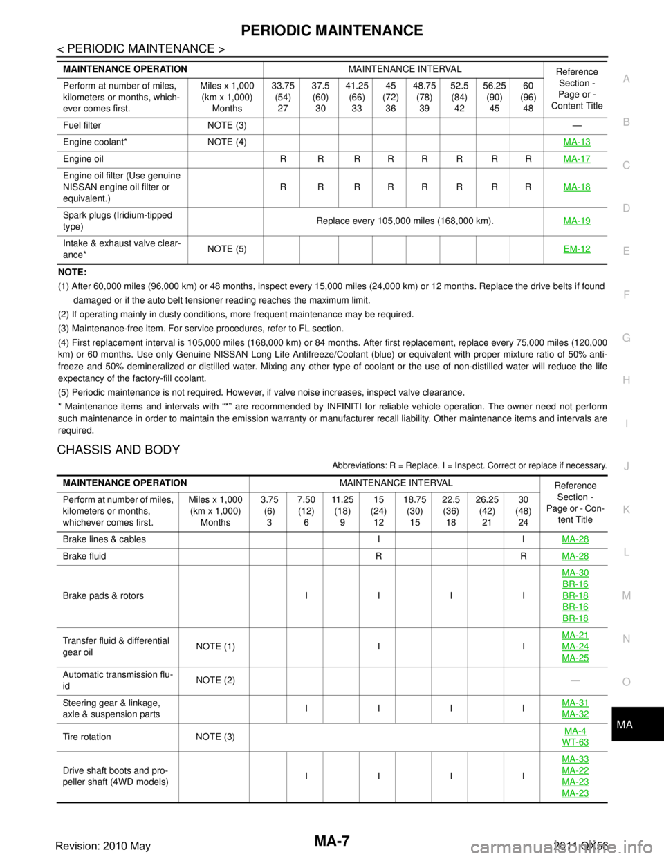
PERIODIC MAINTENANCEMA-7
< PERIODIC MAINTENANCE >
C
DE
F
G H
I
J
K L
M B
MA
N
O A
NOTE:
(1) After 60,000 miles (96,000 km) or 48 months, inspect every 15,000 miles (24,000 km) or 12 months. Replace the drive belts i
f found
damaged or if the auto belt tensioner reading reaches the maximum limit.
(2) If operating mainly in dusty conditions, more frequent maintenance may be required.
(3) Maintenance-free item. For service procedures, refer to FL section.
(4) First replacement interval is 105,000 miles (168,000 km) or 84 months. After first replacement, replace every 75,000 miles (120,000
km) or 60 months. Use only Genu ine NISSAN Long Life Antifreeze/Coo lant (blue) or equivalent with proper mixture ratio of 50% anti-
freeze and 50% demineralized or distilled water. Mixing any other type of coolant or the use of non-distilled water will reduce the life
expectancy of the factory-fill coolant.
(5) Periodic maintenance is not required. However, if valve noise increases, inspect valve clearance.
* Maintenance items and intervals with “*” are recommended by INFINITI for reliable vehicle operation. The owner need not perfo rm
such maintenance in order to maintain the emission warranty or manufacturer recall liability. Other maintenance items and inter vals are
required.
CHASSIS AND BODY
Abbreviations: R = Replace. I = Inspec t. Correct or replace if necessary.
Fuel filter NOTE (3) —
Engine coolant* NOTE (4) MA-13
Engine oil R R R R R R R RMA-17
Engine oil filter (Use genuine
NISSAN engine oil filter or
equivalent.)R R RRRRRR
MA-18
Spark plugs (Iridium-tipped
type)Replace every 105,000 miles (168,000 km).
MA-19
Intake & exhaust valve clear-
ance*NOTE (5)
EM-12
MAINTENANCE OPERATIONMAINTENANCE INTERVAL
Reference
Section -
Page or -
Content Title
Perform at number of miles,
kilometers or months, which-
ever comes first. Miles x 1,000
(km x 1,000)
Months 33.75
(54)
27 37.5
(60)
30 41.25
(66)
33 45
(72)
36 48.75
(78)
39 52.5
(84)
42 56.25
(90)
45 60
(96)
48
MAINTENANCE OPERATION MAINTENANCE INTERVAL
Reference
Section -
Page or - Con- tent Title
Perform at number of miles,
kilometers or months,
whichever comes first. Miles x 1,000
(km x 1,000)
Months 3.75
(6)
3 7.50
(12)
6 11 . 2 5
(18)
9 15
(24)
12 18.75
(30)
15 22.5
(36)
18 26.25
(42)
21 30
(48)
24
Brake lines & cables I I MA-28
Brake fluid R RMA-28
Brake pads & rotors I I I IMA-30
BR-16
BR-18
BR-16
BR-18
Transfer fluid & differential
gear oil
NOTE (1) I I MA-21MA-24
MA-25
Automatic transmission flu-
id
NOTE (2)
—
Steering gear & linkage,
axle & suspension parts IIII
MA-31
MA-32
Tire rotation NOTE (3) MA-4WT-63
Drive shaft boots and pro-
peller shaft (4WD models) IIII MA-33MA-22
MA-23
MA-23
Revision: 2010 May2011 QX56
Page 3679 of 5598
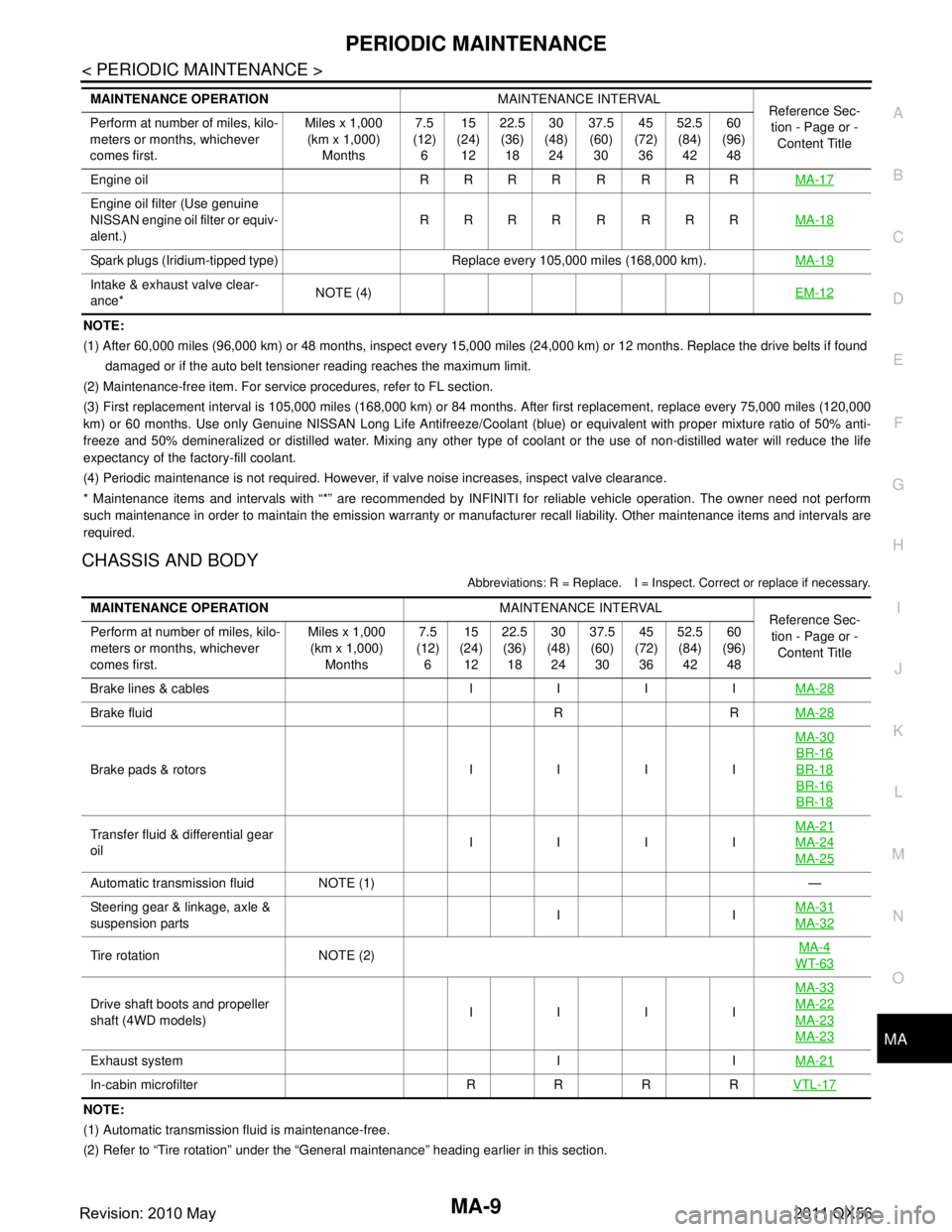
PERIODIC MAINTENANCEMA-9
< PERIODIC MAINTENANCE >
C
DE
F
G H
I
J
K L
M B
MA
N
O A
NOTE:
(1) After 60,000 miles (96,000 km) or 48 months, inspect every 15,000 miles (24,000 km) or 12 months. Replace the drive belts i
f found
damaged or if the auto belt tensioner reading reaches the maximum limit.
(2) Maintenance-free item. For service procedures, refer to FL section.
(3) First replacement interval is 105,000 miles (168,000 km) or 84 months. After first replacement, replace every 75,000 miles (120,000
km) or 60 months. Use only Genu ine NISSAN Long Life Antifreeze/Coo lant (blue) or equivalent with proper mixture ratio of 50% anti-
freeze and 50% demineralized or distilled water. Mixing any other type of coolant or the use of non-distilled water will reduce the life
expectancy of the factory-fill coolant.
(4) Periodic maintenance is not required. However, if valve noise increases, inspect valve clearance.
* Maintenance items and intervals with “*” are recommended by INFINITI for reliable vehicle operation. The owner need not perfo rm
such maintenance in order to maintain the emission warranty or manufacturer recall liability. Other maintenance items and inter vals are
required.
CHASSIS AND BODY
Abbreviations: R = Replace. I = Inspec t. Correct or replace if necessary.
NOTE:
(1) Automatic transmission fluid is maintenance-free.
(2) Refer to “Tire rotation” under the “General maintenance” heading earlier in this section.
Engine oil R R R R R R R R
MA-17
Engine oil filter (Use genuine
NISSAN engine oil filter or equiv-
alent.)RRRR R RRR
MA-18
Spark plugs (Iridium-tipped type) Replace every 105,000 miles (168,000 km). MA-19
Intake & exhaust valve clear-
ance*NOTE (4)
EM-12
MAINTENANCE OPERATIONMAINTENANCE INTERVAL
Reference Sec-
tion - Page or -
Content Title
Perform at number of miles, kilo-
meters or months, whichever
comes first. Miles x 1,000
(km x 1,000)
Months 7.5
(12)
6 15
(24)
12 22.5
(36)
18 30
(48)
24 37.5
(60)
30 45
(72)
36 52.5
(84)
42 60
(96)
48
MAINTENANCE OPERATION MAINTENANCE INTERVAL
Reference Sec-
tion - Page or - Content Title
Perform at number of miles, kilo-
meters or months, whichever
comes first. Miles x 1,000
(km x 1,000) Months 7.5
(12) 6 15
(24) 12 22.5
(36) 18 30
(48) 24 37.5
(60) 30 45
(72) 36 52.5
(84) 42 60
(96) 48
Brake lines & cables I I I I MA-28
Brake fluid R RMA-28
Brake pads & rotors I I I IMA-30
BR-16
BR-18
BR-16
BR-18
Transfer fluid & differential gear
oil
IIIIMA-21MA-24
MA-25
Automatic transmission fluid NOTE (1)
—
Steering gear & linkage, axle &
suspension parts II
MA-31
MA-32
Tire rotation NOTE (2) MA-4WT-63
Drive shaft boots and propeller
shaft (4WD models) IIIIMA-33MA-22
MA-23
MA-23
Exhaust system I I
MA-21
In-cabin microfilter R R R RVTL-17
Revision: 2010 May2011 QX56
Page 3750 of 5598
MWI
COMPONENT PARTSMWI-7
< SYSTEM DESCRIPTION >
C
DE
F
G H
I
J
K L
M B A
O P
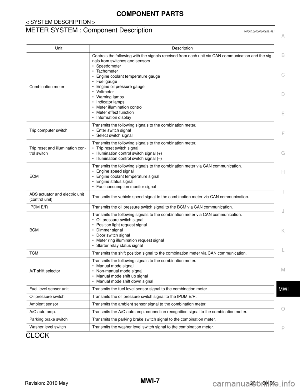
METER SYSTEM : Com ponent DescriptionINFOID:0000000006221691
CLOCK
Unit Description
Combination meter Controls the following with the signals received from each unit via CAN communication and the sig-
nals from switches and sensors.
Speedometer
Tachometer
Engine coolant temperature gauge
Fuel gauge
Engine oil pressure gauge
Voltmeter
Warning lamps
Indicator lamps
Meter illumination control
Meter effect function
Information display
Trip computer switch Transmits the following signals to the combination meter.
Enter switch signal
Select switch signal
Trip reset and illumination con-
trol switch Transmits the following signals to the combination meter.
Trip reset switch signal
Illumination control switch signal (+)
Illumination control switch signal (
−)
ECM Transmits the following signals to the combination meter via CAN communication.
Engine speed signal
Engine coolant temperature signal
Engine status signal
Fuel consumption monitor signal
ABS actuator and electric unit
(control unit) Transmits the vehicle speed signal to the combination meter via CAN communication.
IPDM E/R Transmits the oil pressure switch signal to the BCM via CAN communication.
BCM Transmits the following signals to the combination meter via CAN communication.
Oil pressure switch signal
Position light request signal
Dimmer signal
Door switch signal
Meter ring illumination request signal
Starter relay status signal
TCM Transmits the shift position signal to the combination meter via CAN communication.
A/T shift selector Transmits the following signals to the combination meter.
Manual mode signal
Non-manual mode signal
Manual mode shift up signal
Manual mode shift down signal
Fuel level sensor unit Transmits the fuel level sensor signal to the combination meter.
Oil pressure switch Transmits the oil pressure switch signal to the IPDM E/R.
Ambient sensor Transmits the ambient sensor signal to the combination meter.
A/C auto amp. Transmits the A/C auto amp. connection recognition signal to the combination meter.
Parking brake switch Transmits the parking brake switch signal to the combination meter.
Washer level switch Transmits the washer level switch signal to the combination meter.
Revision: 2010 May2011 QX56
Page 3772 of 5598
MWI
DIAGNOSIS SYSTEM (COMBINATION METER)
MWI-29
< SYSTEM DESCRIPTION >
C
D E
F
G H
I
J
K L
M B A
O P
DIAGNOSIS SYSTEM (COMBINATION METER)
On Board Diagnosis FunctionINFOID:0000000006221719
ON BOARD DIAGNOSIS ITEM
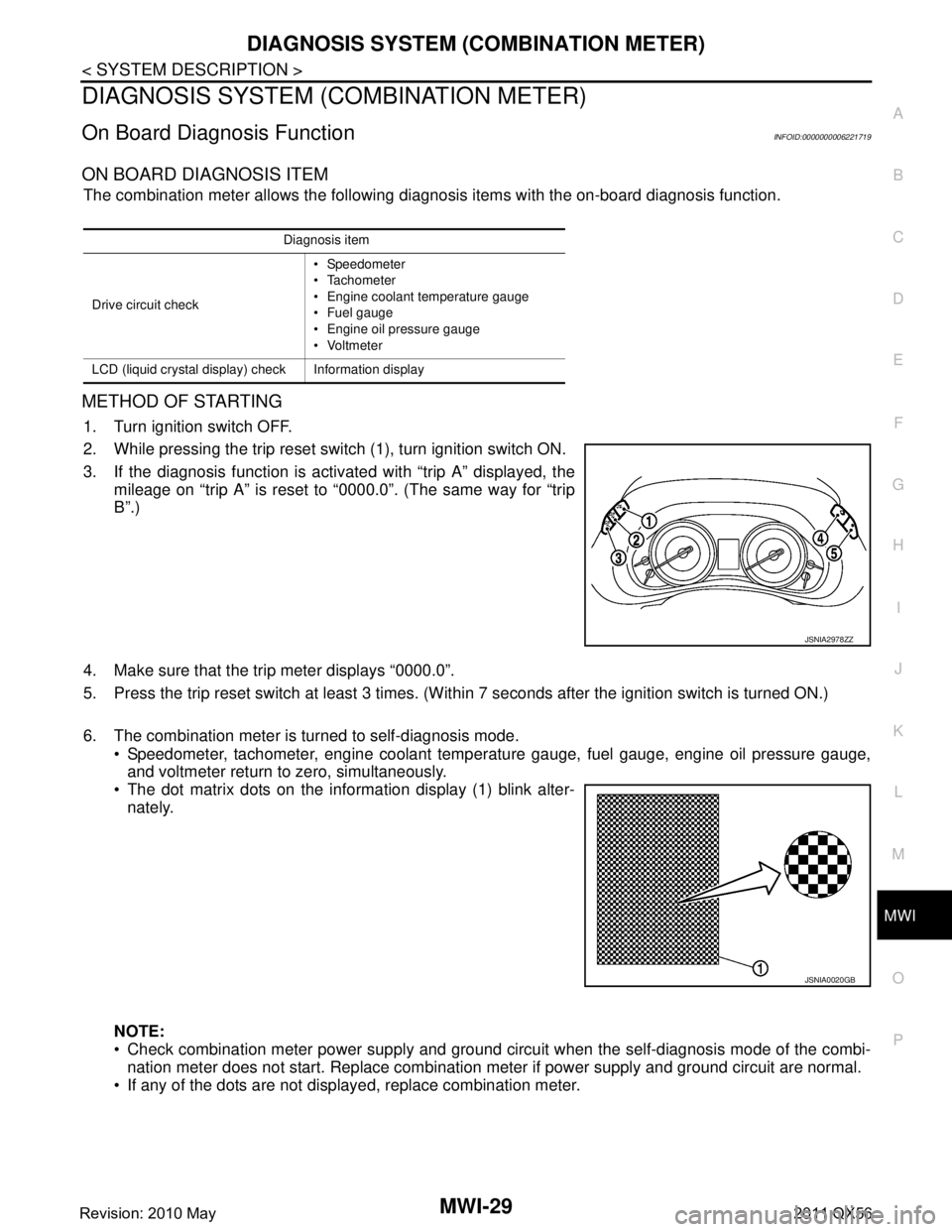
The combination meter allows the following diagnosis items with the on-board diagnosis function.
METHOD OF STARTING
1. Turn ignition switch OFF.
2. While pressing the trip reset switch (1), turn ignition switch ON.
3. If the diagnosis function is activated with “trip A” displayed, the
mileage on “trip A” is reset to “0000.0”. (The same way for “trip
B”.)
4. Make sure that the trip meter displays “0000.0”.
5. Press the trip reset switch at least 3 times. (Wit hin 7 seconds after the ignition switch is turned ON.)
6. The combination meter is turned to self-diagnosis mode. Speedometer, tachometer, engine coolant temper ature gauge, fuel gauge, engine oil pressure gauge,
and voltmeter return to zero, simultaneously.
The dot matrix dots on the information display (1) blink alter-
nately.
NOTE:
Check combination meter power supply and ground circuit when the self-diagnosis mode of the combi- nation meter does not start. Replace combination meter if power supply and ground circuit are normal.
If any of the dots are not displayed, replace combination meter.
Diagnosis item
Drive circuit check Speedometer
Tachometer
Engine coolant temperature gauge
Fuel gauge
Engine oil pressure gauge
Voltmeter
LCD (liquid crystal display) check Information display
JSNIA2978ZZ
JSNIA0020GB
Revision: 2010 May2011 QX56
Page 3776 of 5598
MWI
DIAGNOSIS SYSTEM (COMBINATION METER)
MWI-33
< SYSTEM DESCRIPTION >
C
D E
F
G H
I
J
K L
M B A
O P
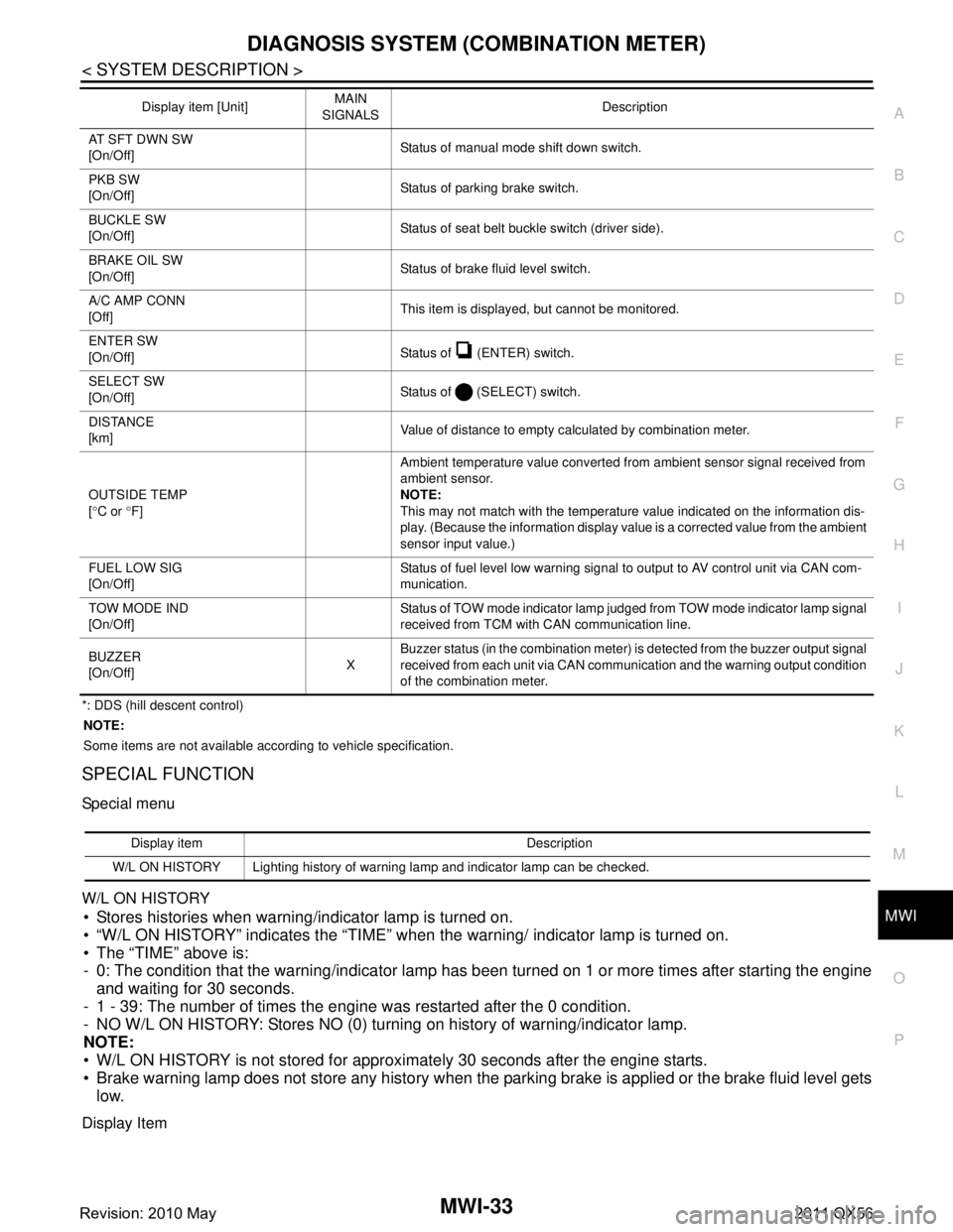
*: DDS (hill descent control) NOTE:
Some items are not available according to vehicle specification.
SPECIAL FUNCTION
Special menu
W/L ON HISTORY
Stores histories when warning/indicator lamp is turned on.
“W/L ON HISTORY” indicates the “TIME” when the warning/ indicator lamp is turned on.
The “TIME” above is:
- 0: The condition that the warning/indicator lamp has been turned on 1 or more times after starting the engine and waiting for 30 seconds.
- 1 - 39: The number of times the engine was restarted after the 0 condition.
- NO W/L ON HISTORY: Stores NO (0) turning on history of warning/indicator lamp.
NOTE:
W/L ON HISTORY is not stored for approximately 30 seconds after the engine starts.
Brake warning lamp does not store any history when the parking brake is applied or the brake fluid level gets
low.
Display Item
AT SFT DWN SW
[On/Off] Status of manual mode shift down switch.
PKB SW
[On/Off] Status of parking brake switch.
BUCKLE SW
[On/Off] Status of seat belt buckle switch (driver side).
BRAKE OIL SW
[On/Off] Status of brake fluid level switch.
A/C AMP CONN
[Off] This item is displayed, but cannot be monitored.
ENTER SW
[On/Off] Status of (ENTER) switch.
SELECT SW
[On/Off] Status of (SELECT) switch.
DISTANCE
[km] Value of distance to empty calculated by combination meter.
OUTSIDE TEMP
[ ° C or °F] Ambient temperature value converted from ambient sensor signal received from
ambient sensor.
NOTE:
This may not match with the temperature value indicated on the information dis-
play. (Because the information display value is a corrected value from the ambient
sensor input value.)
FUEL LOW SIG
[On/Off] Status of fuel level low warning signal to output to AV control unit via CAN com-
munication.
TOW MODE IND
[On/Off] Status of TOW mode indicator lamp judged from TOW mode indicator lamp signal
received from TCM with CAN communication line.
BUZZER
[On/Off] XBuzzer status (in the combination meter) is detected from the buzzer output signal
received from each unit via CAN communication and the warning output condition
of the combination meter.
Display item [Unit]
MAIN
SIGNALS Description
Display item Description
W/L ON HISTORY Lighting history of warning lamp and indicator lamp can be checked.
Revision: 2010 May2011 QX56
Page 3786 of 5598
MWI
COMBINATION METERMWI-43
< ECU DIAGNOSIS INFORMATION >
C
DE
F
G H
I
J
K L
M B A
O P
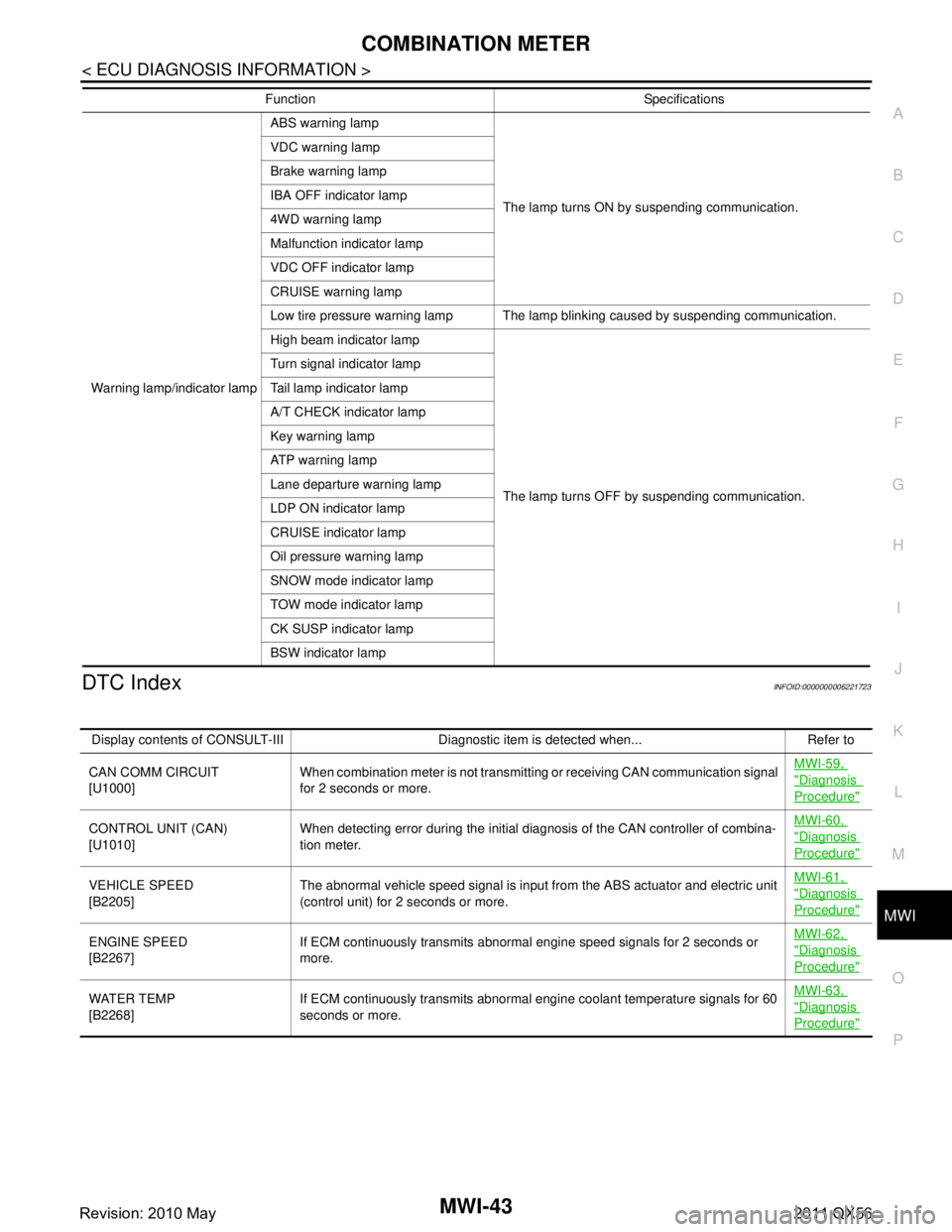
DTC IndexINFOID:0000000006221723
Warning lamp/indicator lamp ABS warning lamp
The lamp turns ON by suspending communication.
VDC warning lamp
Brake warning lamp
IBA OFF indicator lamp
4WD warning lamp
Malfunction indicator lamp
VDC OFF indicator lamp
CRUISE warning lamp
Low tire pressure warning lamp The lamp blinking caused by suspending communication.
High beam indicator lamp
The lamp turns OFF by suspending communication.
Turn signal indicator lamp
Tail lamp indicator lamp
A/T CHECK indicator lamp
Key warning lamp
AT P w a r n i n g l a m p
Lane departure warning lamp
LDP ON indicator lamp
CRUISE indicator lamp
Oil pressure warning lamp
SNOW mode indicator lamp
TOW mode indicator lamp
CK SUSP indicator lamp
BSW indicator lamp
Function Specifications
Display contents of CONSULT-III Diagnostic item is detected when... Refer to
CAN COMM CIRCUIT
[U1000] When combination meter is not transmitting or receiving CAN communication signal
for 2 seconds or more. MWI-59,
"Diagnosis
Procedure"
CONTROL UNIT (CAN)
[U1010]
When detecting error during the initial diagnosis of the CAN controller of combina-
tion meter. MWI-60, "Diagnosis
Procedure"
VEHICLE SPEED
[B2205]
The abnormal vehicle speed signal is input from the ABS actuator and electric unit
(control unit) for
2 seconds or more. MWI-61, "Diagnosis
Procedure"
ENGINE SPEED
[B2267]
If ECM continuously transmits abnormal engine speed signals for 2 seconds or
more. MWI-62, "Diagnosis
Procedure"
WATER TEMP
[B2268]
If ECM continuously transmits abnormal engine coolant temperature signals for 60
seconds or more. MWI-63, "Diagnosis
Procedure"
Revision: 2010 May2011 QX56