2011 INFINITI QX56 fuel tank removal
[x] Cancel search: fuel tank removalPage 2937 of 5598
FL-8
< REMOVAL AND INSTALLATION >
FUEL TANK
FUEL TANK
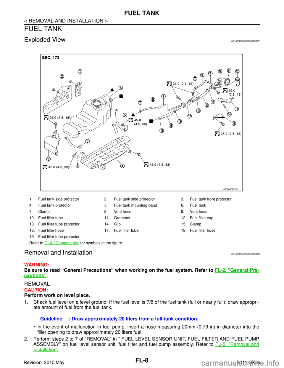
Exploded ViewINFOID:0000000006289687
Removal and InstallationINFOID:0000000006289688
WARNING:
Be sure to read “General Precautions” when working on the fuel system. Refer to FL-2, "
General Pre-
cautions".
REMOVAL
CAUTION:
Perform work on level place.
1. Check fuel level on a level ground. If the fuel level is 7/8 of the fuel tank (full or nearly full), draw appropri-
ate amount of fuel from the fuel tank.
In the event of malfunction in fuel pump, insert a hose measuring 20mm (0.79 in) in diameter into the
filler opening to draw approximately 20 liters fuel.
2. Perform steps 2 to 7 of “REMOVAL” in “ FUEL LEVEL SENSOR UNIT, FUEL FILTER AND FUEL PUMP ASSEMBLY” on fuel level sensor unit, fuel filter and fuel pump assembly. Refer to FL-5, "
Removal and
Installation".
1. Fuel tank side protector 2. Fuel tank side protector 3. Fuel tank front protector
4. Fuel tank protector 5. Fuel tank mounting band 6. Fuel tank
7. Clamp 8. Vent hose 9. Vent hose
10. Fuel filler tube 11. Grommet 12. Fuel filler cap
13. Fuel filler tube protector 14. Clip 15. Clamp
16. Fuel filler hose 17. Fuel filler tube 18. Fuel filler hose
19. Fuel filler tube protector
Refer to GI-4, "
Components" for symbols in the figure.
JSBIA0381GB
Guideline : Draw approximately 20 li ters from a full-tank condition.
Revision: 2010 May2011 QX56
Page 2938 of 5598
FUEL TANKFL-9
< REMOVAL AND INSTALLATION >
C
DE
F
G H
I
J
K L
M A
FL
NP
O
3. Remove LH rear wheel and tire.
4. Disconnect fuel filler hose, vent hose and EVAP hose at fuel tank side.
5. Remove fuel tank protector.
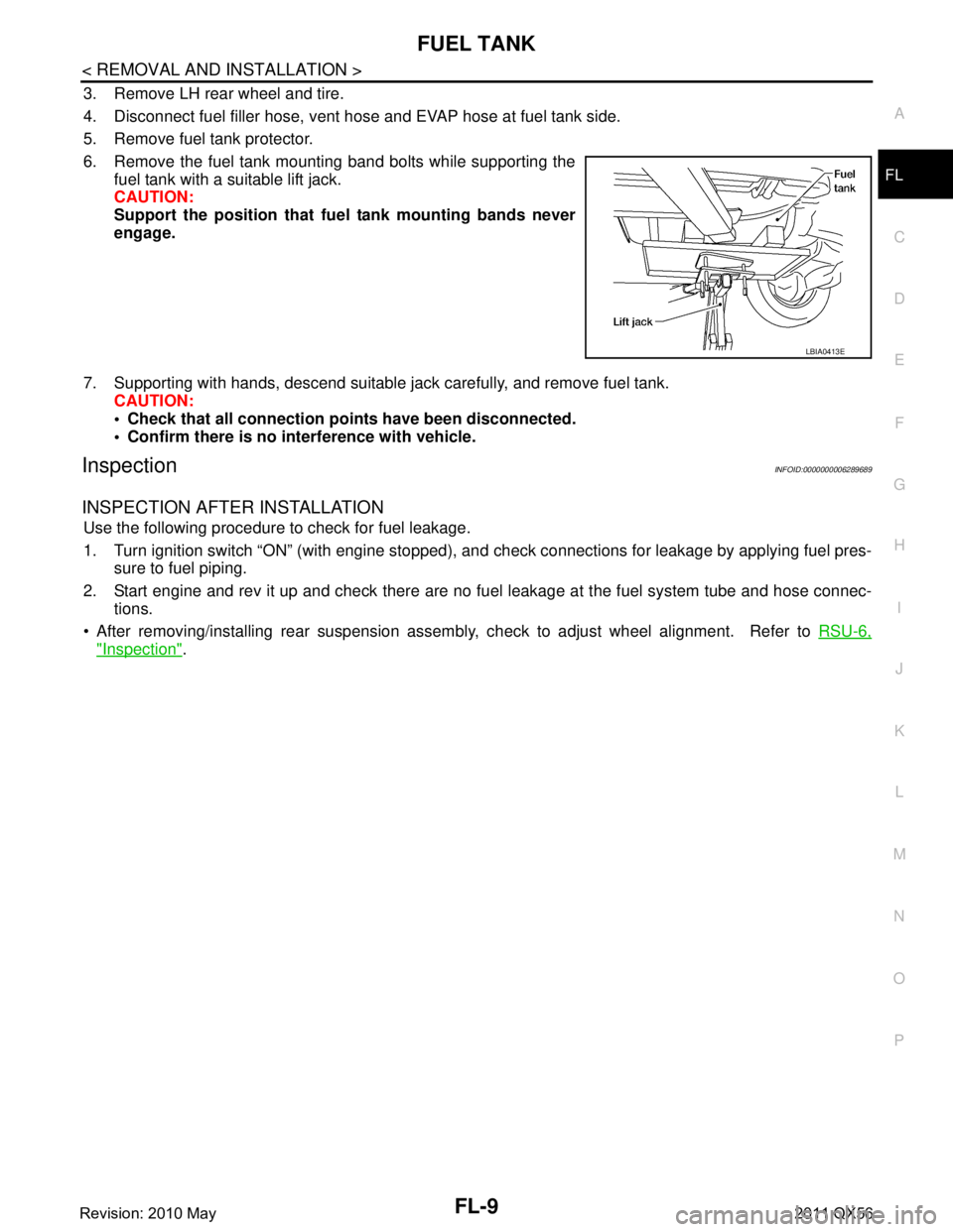
6. Remove the fuel tank mounting band bolts while supporting the
fuel tank with a suitable lift jack.
CAUTION:
Support the position that fu el tank mounting bands never
engage.
7. Supporting with hands, descend suitable jack carefully, and remove fuel tank. CAUTION:
Check that all connection po ints have been disconnected.
Confirm there is no interference with vehicle.
InspectionINFOID:0000000006289689
INSPECTION AFTER INSTALLATION
Use the following procedure to check for fuel leakage.
1. Turn ignition switch “ON” (with engine stopped), and check connections for leakage by applying fuel pres-
sure to fuel piping.
2. Start engine and rev it up and check there are no f uel leakage at the fuel system tube and hose connec-
tions.
After removing/installing rear suspension assembly, check to adjust wheel alignment. Refer to RSU-6,
"Inspection".
LBIA0413E
Revision: 2010 May2011 QX56
Page 2993 of 5598
PRECAUTIONSGI-29
< PRECAUTION >
C
DE
F
G H
I
J
K L
M B
GI
N
O P
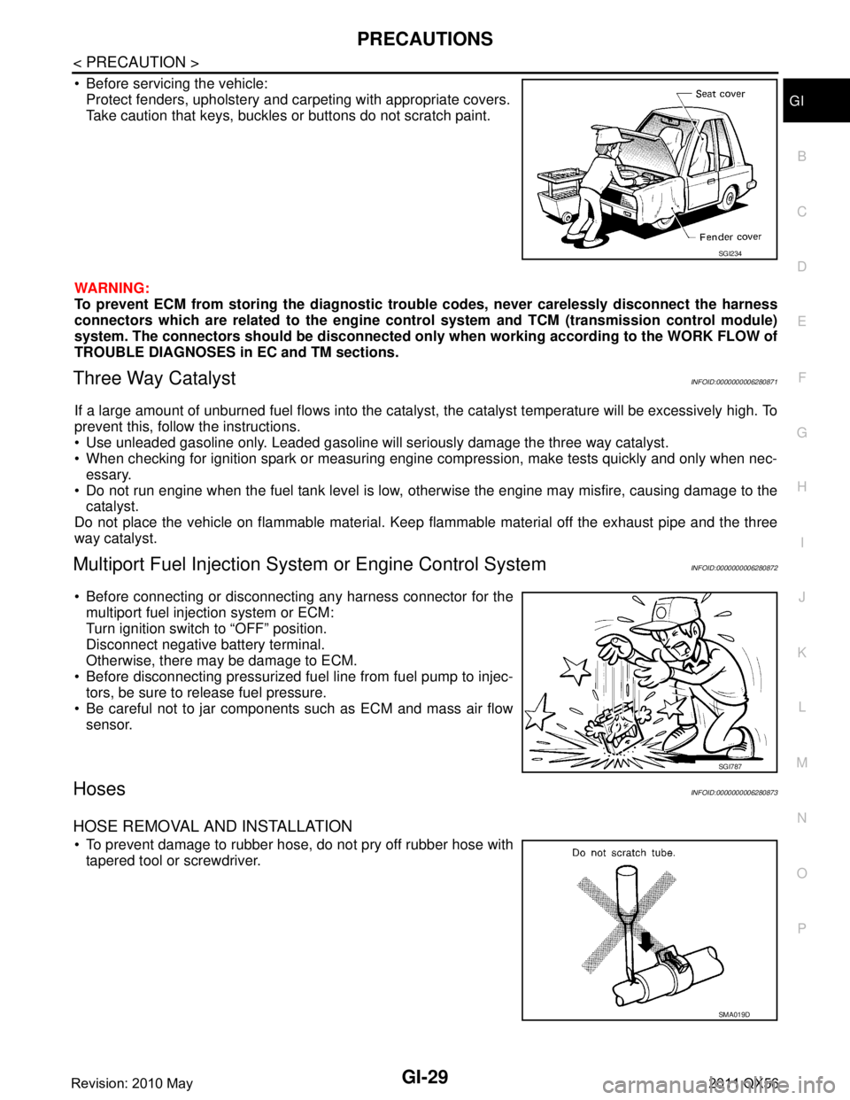
Before servicing the vehicle: Protect fenders, upholstery and carpeting with appropriate covers.
Take caution that keys, buckles or buttons do not scratch paint.
WARNING:
To prevent ECM from storing the diagnostic trou ble codes, never carelessly disconnect the harness
connectors which are related to the engine cont rol system and TCM (transmission control module)
system. The connectors should be disconnected only when working according to the WORK FLOW of
TROUBLE DIAGNOSES in EC and TM sections.
Three Way CatalystINFOID:0000000006280871
If a large amount of unburned fuel flows into the catalyst , the catalyst temperature will be excessively high. To
prevent this, follow the instructions.
Use unleaded gasoline only. Leaded gasoline will seriously damage the three way catalyst.
When checking for ignition spark or measuring engine compression, make tests quickly and only when nec- essary.
Do not run engine when the fuel tank level is low, otherwise the engine may misfire, causing damage to the
catalyst.
Do not place the vehicle on flammable material. Keep flammable material off the exhaust pipe and the three
way catalyst.
Multiport Fuel Inje ction System or Engine Control SystemINFOID:0000000006280872
Before connecting or disconnecti ng any harness connector for the
multiport fuel injection system or ECM:
Turn ignition switch to “OFF” position.
Disconnect negative battery terminal.
Otherwise, there may be damage to ECM.
Before disconnecting pressurized fuel line from fuel pump to injec- tors, be sure to release fuel pressure.
Be careful not to jar components such as ECM and mass air flow sensor.
HosesINFOID:0000000006280873
HOSE REMOVAL AND INSTALLATION
To prevent damage to rubber hose, do not pry off rubber hose withtapered tool or screwdriver.
SGI234
SGI787
SMA019D
Revision: 2010 May2011 QX56
Page 3671 of 5598
MA-1
MAINTENANCE
C
DE
F
G H
I
J
K L
M B
MA
SECTION MA
N
O A
CONTENTS
MAINTENANCE
PREPARATION .............
...............................3
PREPARATION .............................................. .....3
Special Service Tool ........................................... ......3
Commercial Service Tool ..........................................3
PERIODIC MAINTENANCE ..........................4
GENERAL MAINTENANCE ........................... .....4
Explanation of General Maintenance .................. ......4
PERIODIC MAINTENANCE ................................6
Introduction of Periodic Maintenance .................. ......6
Schedule 1 ................................................................6
Schedule 2 ................................................................8
RECOMMENDED FLUIDS AND LUBRI-
CANTS ................................................................
10
Fluids and Lubricants .......................................... ....10
Engine Oil Recommendation ..................................10
Anti-Freeze Coolant Mixture Ratio ..........................11
ENGINE MAINTENANCE ...................................12
DRIVE BELTS ....................................................... ....12
DRIVE BELTS : Exploded View ..............................12
DRIVE BELTS : Checking .......................................12
DRIVE BELTS : Tension Adjustment .....................12
ENGINE COOLANT ............................................... ....12
ENGINE COOLANT : Inspection .............................12
ENGINE COOLANT : Draining ................................13
ENGINE COOLANT : Refilling ................................13
ENGINE COOLANT : Flushing ...............................15
RESERVOIR TANK CAP ..........................................15
RESERVOIR TANK CAP : Inspection ................. ....15
RADIATOR ............................................................ ....16
RADIATOR : Inspection ..........................................16
FUEL LINES .......................................................... ....16
FUEL LINES : Inspection ........................................17
AIR CLEANER FILTER ......................................... ....17
AIR CLEANER FILTER : Removal and Installation
....
17
ENGINE OIL ........................................................... ....17
ENGINE OIL : Draining ............................................17
ENGINE OIL : Refilling ............................................17
OIL FILTER ............................................................ ....18
OIL FILTER : Removal and Installation ...................18
SPARK PLUG ........................................................ ....18
SPARK PLUG : Removal and Installation ...............19
SPARK PLUG : Inspection ......................................19
EVAP VAPOR LINES ............................................ ....20
EVAP VAPOR LINES : Inspection ...........................20
CHASSIS MAINTENANCE ...............................21
EXHAUST SYSTEM . ..................................................21
EXHAUST SYSTEM : Inspec tion ............................21
A/T FLUID .............................................................. ....21
A/T FLUID : Inspection ............................................21
TRANSFER FLUID ................................................ ....21
TRANSFER FLUID : Inspection ..............................21
TRANSFER FLUID : Draining .................................21
TRANSFER FLUID : Refilling ..................................22
FRONT PROPELLER SHAFT: 2F P15 ................. ....22
FRONT PROPELLER SHAFT: 2F P15 : Inspec-
tion ...........................................................................
22
REAR PROPELLER SHAFT: 2F P26 .................... ....23
REAR PROPELLER SHAFT: 2F P26 : Inspection ....23
REAR PROPELLER SHAFT: 2S1410 ................... ....23
REAR PROPELLER SHAFT: 2S1410 : Inspection ....23
FRONT DIFFERENTIAL GEAR OIL: R180A ........ ....24
FRONT DIFFERENTIAL GEAR OIL: R180A : In-
spection ...................................................................
24
Revision: 2010 May2011 QX56
Page 3686 of 5598
MA-16
< PERIODIC MAINTENANCE >
ENGINE MAINTENANCE
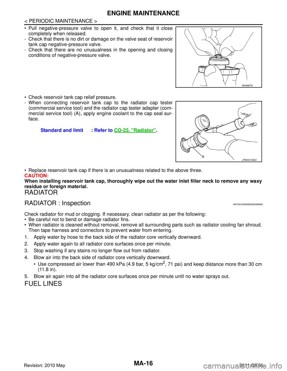
Pull negative-pressure valve to open it, and check that it closecompletely when released.
- Check that there is no dirt or damage on the valve seat of reservoir
tank cap negative-pressure valve.
- Check that there are no unusualness in the opening and closing conditions of negative-pressure valve.
Check reservoir tank cap relief pressure.
- When connecting reservoir tank cap to the radiator cap tester (commercial service tool) and the radiator cap tester adapter (com-
mercial service tool) (A), apply engine coolant to the cap seal sur-
face.
Replace reservoir tank cap if there is an unusualness related to the above three.
CAUTION:
When installing reservoir tank cap, thoroughly wipe out the water inlet filler neck to remove any waxy
residue or foreign material.
RADIATOR
RADIATOR : InspectionINFOID:0000000006394849
Check radiator for mud or clogging. If nec essary, clean radiator as per the following:
Be careful not to bend or damage radiator fins.
When radiator is cleaned without removal, remove all surrounding parts such as radiator cooling fan shroud. Then tape harness and connectors to prevent water from entering.
1. Apply water by hose to the back side of the radiator core vertically downward.
2. Apply water again to all radiator core surfaces once per minute.
3. Stop washing if any stains no longer flow out from radiator.
4. Blow air into the back side of radiator core vertically downward. Use compressed air lower than 490 kPa (4.9 bar, 5 kg/cm
2, 71 psi) and keep distance more than 30 cm
(11.8 in).
5. Blow air again into all the radiator core su rfaces once per minute until no water sprays out.
FUEL LINES
SMA967B
Standard and limit : Refer to CO-23, "Radiator".
JPBIA0109ZZ
Revision: 2010 May2011 QX56
Page 3687 of 5598
ENGINE MAINTENANCEMA-17
< PERIODIC MAINTENANCE >
C
DE
F
G H
I
J
K L
M B
MA
N
O A
FUEL LINES : InspectionINFOID:0000000006394850
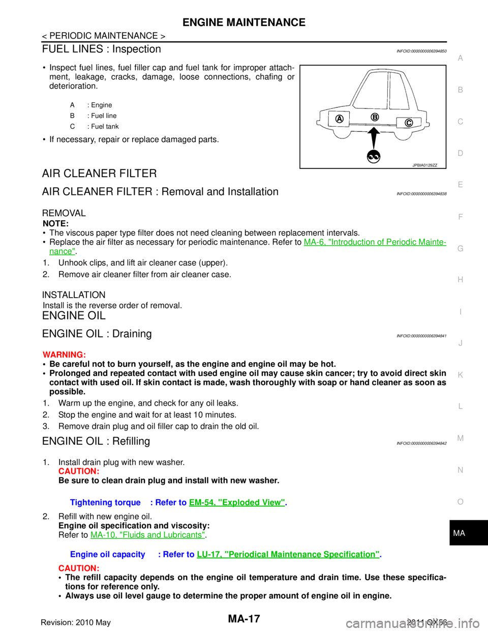
Inspect fuel lines, fuel filler cap and fuel tank for improper attach-
ment, leakage, cracks, damage, loose connections, chafing or
deterioration.
If necessary, repair or replace damaged parts.
AIR CLEANER FILTER
AIR CLEANER FILTER : Removal and InstallationINFOID:0000000006394838
REMOVAL
NOTE:
The viscous paper type filter does not need cleaning between replacement intervals.
Replace the air filter as necessary for periodic maintenance. Refer to MA-6, "
Introduction of Periodic Mainte-
nance".
1. Unhook clips, and lift air cleaner case (upper).
2. Remove air cleaner filter from air cleaner case.
INSTALLATION
Install is the reverse order of removal.
ENGINE OIL
ENGINE OIL : DrainingINFOID:0000000006394841
WARNING:
Be careful not to burn yourself, as th e engine and engine oil may be hot.
Prolonged and repeated contact with used engine oil may cau se skin cancer; try to avoid direct skin
contact with used oil. If skin contact is made, w ash thoroughly with soap or hand cleaner as soon as
possible.
1. Warm up the engine, and check for any oil leaks.
2. Stop the engine and wait for at least 10 minutes.
3. Remove drain plug and oil filler cap to drain the old oil.
ENGINE OIL : RefillingINFOID:0000000006394842
1. Install drain plug with new washer. CAUTION:
Be sure to clean drain plug and install with new washer.
2. Refill with new engine oil. Engine oil specificat ion and viscosity:
Refer to MA-10, "
Fluids and Lubricants".
CAUTION:
The refill capacity depends on the engine oi l temperature and drain time. Use these specifica-
tions for reference only.
Always use oil level gauge to determine the proper amount of engine oil in engine.
A : Engine
B : Fuel line
C : Fuel tank
JPBIA0129ZZ
Tightening torque : Refer to EM-54, "Exploded View".
Engine oil capacity : Refer to LU-17, "
Periodical Maintenance Specification".
Revision: 2010 May2011 QX56
Page 3818 of 5598
MWI
THE FUEL GAUGE INDICATOR DOES NOT OPERATE
MWI-75
< SYMPTOM DIAGNOSIS >
C
D E
F
G H
I
J
K L
M B A
O P
SYMPTOM DIAGNOSIS
THE FUEL GAUGE INDICA TOR DOES NOT OPERATE
DescriptionINFOID:0000000006221757
Fuel gauge will not indicate from a certain position.
Diagnosis ProcedureINFOID:0000000006221758
1.CHECK COMBINATION METER OUTPUT SIGNAL
1. Connect CONSULT-III.
2. Select the “Data Monitor” for the “METER/M&A” and compare the “FUEL METER” monitor value with the
fuel gauge reading on the combination meter. Refer to MWI-69, "
Component Function Check".
Does monitor value match fuel gauge reading?
YES >> GO TO 2.
NO >> Replace combination meter. Refer to MWI-85, "
Removal and Installation".
2.CHECK FUEL LEVEL SENSOR SIGNAL CIRCUIT
Check the fuel level sensor signal circuit. Refer to MWI-69, "
DiagnosisProcedure".
Is the inspection result normal?
YES >> GO TO 3.
NO >> Repair harness or connector.
3.CHECK FUEL LEVEL SENSOR UNIT
Perform a unit check for the fuel level sensor unit. Refer to MWI-70, "
Component Inspection".
Is the inspection result normal?
YES >> GO TO 4.
NO >> Replace fuel level sensor unit. Refer to FL-5, "
Removal and Installation".
4.CHECK FLOAT INTERFERENCE
Check that the float arm interferes with or binds to other components in the fuel tank.
Is the inspection result normal?
YES >> Replace combination meter. Refer to MWI-85, "Removal and Installation".
NO >> Repair or replace malfunctioning parts.
Revision: 2010 May2011 QX56