Page 4991 of 5598

ST-4
< PRECAUTION >
PRECAUTIONS
5. When the repair work is completed, re-connect both battery cables. With the brake pedal released, turn
the push-button ignition switch from ACC position to ON position, then to LOCK position. (The steering
wheel will lock when the push-button igniti on switch is turned to LOCK position.)
6. Perform self-diagnosis check of all control units using CONSULT-III.
Service Notice or Precautions for Steering SystemINFOID:0000000006225573
In case of removing steering gear assembly, make the final tightening with grounded and unloaded vehicle condition, and then check wheel alignment.
Observe the following precautions when disassembling.
- Before disassembly, thoroughly clean the outside of the unit.
- Disassembly should be done in a clean work area. It is im portant to prevent the internal parts from becoming
contaminated by dirt or other foreign matter.
- For easier and proper assembly, place disassembled parts in order on a parts rack.
- Use nylon cloth or paper towels to clean the parts; co mmon shop rags can leave lint that might interfere with
their operation.
- Never reuse non-reusable parts.
- Before assembling, apply the specified grease to the directed parts.
Revision: 2010 May2011 QX56
Page 4992 of 5598
PREPARATIONST-5
< PREPARATION >
C
DE
F
H I
J
K L
M A
B
ST
N
O P
PREPARATION
PREPARATION
Special Service ToolsINFOID:0000000006225574
The actual shapes of Kent-Moore t ools may differ from those of special service tools illustrated here.
Tool number
(Kent-Moore No.)
Tool name Description
ST27180001
(J-25726-A)
Steering wheel puller Removing steering wheel
ST3127S000
(J-25765-A)
Preload gauge Inspecting sliding torque, steering torque, and
rotating torque for ball joint
KV48103400
(—)
Preload adapter Inspecting rotating torque
KV40107300
(—)
Boot band crimping tool Installing boot band
KV48103500
(J-26357)
Oil pressure gauge Measuring oil pump relief pressure
KV48102500
(J-33914)
Oil pressure gauge adapter Measuring oil pump relief pressure
ZZA0819D
ZZA0806D
ZZA0824D
ZZA1229D
S-NT547
S-NT542
Revision: 2010 May2011 QX56
Page 4994 of 5598
COMPONENT PARTSST-7
< SYSTEM DESCRIPTION >
C
DE
F
H I
J
K L
M A
B
ST
N
O P
SYSTEM DESCRIPTION
COMPONENT PARTS
Component Parts Locatio n (Heated Steering Wheel)INFOID:0000000006225576
Component Description (Heated Steering Wheel)INFOID:0000000006225577
Heated Steering WheelINFOID:0000000006225578
The heated steering wheel is activated by the pow er supply from the heated steering wheel relay.
1. Heated steering wheel relay 2. Heated steering wheel switch 3. Heated steering wheel
A. Engine room right side
JSGIA0824ZZ
Part name Reference/Function
Heated steering wheel Heating element Refer to ST-7, "
Heated Steering Wheel".
Thermostat
Heated steering wheel relay Refer to ST-8, "
Heated Steering Wheel Relay".
Heated steering wheel switch Timer Refer to ST-8, "
Heated Steering Wheel Switch".
Revision: 2010 May2011 QX56
Page 4995 of 5598
ST-8
< SYSTEM DESCRIPTION >
COMPONENT PARTS
Furthermore, the heated steering wheel incorporates a heating element and a thermostat to control heated
steering wheel temperatures.
Heating element: Heat is generated by the passage of an electric current.
Thermostat: ON/OFF operation of power supply at a certain temperature.
Heated Steering Wheel SwitchINFOID:0000000006225579
Controls the heated steering wheel relay and operates the heated steering wheel system.
The heated steering wheel switch incorporates a ti mer and turns OFF the heated steering wheel relay when
operating time reaches a certain time.
- Timer: ON/OFF operation of the heated st eering wheel relay at a certain time.
Turns the indicator lamp ON when the system is activated.
Heated Steering Wheel RelayINFOID:0000000006225580
Operates the heated steering system with the control signal from the heated steering wheel switch.
Revision: 2010 May2011 QX56
Page 4996 of 5598

SYSTEMST-9
< SYSTEM DESCRIPTION >
C
DE
F
H I
J
K L
M A
B
ST
N
O P
SYSTEM
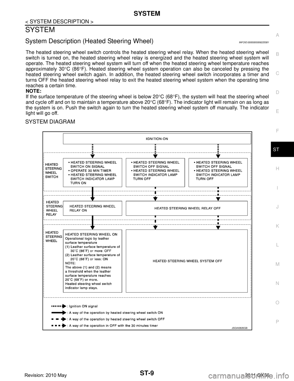
System Description (Heated Steering Wheel)INFOID:0000000006225581
The heated steering wheel switch controls the heated steering wheel relay. When the heated steering wheel
switch is turned on, the heated steering wheel relay is energized and the heated steering wheel system will
operate. The heated steering wheel system will turn of f when the heated steering wheel temperature reaches
approximately 30 °C (86 °F). Heated steering wheel system operati on can also be canceled by pressing the
heated steering wheel switch again. In addition, the heat ed steering wheel switch incorporates a timer and
turns OFF the heated steering wheel relay to exit the heated steering wheel system when the operating time
reaches a certain time.
NOTE:
If the surface temperature of the steering wheel is below 20 °C (68 °F), the system will heat the steering wheel
and cycle off and on to maintain a temperature above 20 °C (68 °F). The indicator light will remain on as long as
the system is on. Push the switch again to turn t he heated steering wheel system off manually. The indicator
light will go off.
SYSTEM DIAGRAM
JSGIA0826GB
Revision: 2010 May2011 QX56
Page 4997 of 5598
ST-10
< WIRING DIAGRAM >
HEATED STEERING WHEEL
WIRING DIAGRAM
HEATED STEERING WHEEL
Wiring DiagramINFOID:0000000006225582
JCGWM0373GB
Revision: 2010 May2011 QX56
Page 4998 of 5598
HEATED STEERING WHEELST-11
< WIRING DIAGRAM >
C
DE
F
H I
J
K L
M A
B
ST
N
O P
JCGWM0390GB
Revision: 2010 May2011 QX56
Page 4999 of 5598
ST-12
< WIRING DIAGRAM >
HEATED STEERING WHEEL
JCGWM0391GB
Revision: 2010 May2011 QX56