2011 INFINITI QX56 ECU
[x] Cancel search: ECUPage 1507 of 5598

BCM, IPDM E/RDEF-15
< ECU DIAGNOSIS INFORMATION >
C
DE
F
G H
I
J
K
M A
B
DEF
N
O P
ECU DIAGNOSIS INFORMATION
BCM, IPDM E/R
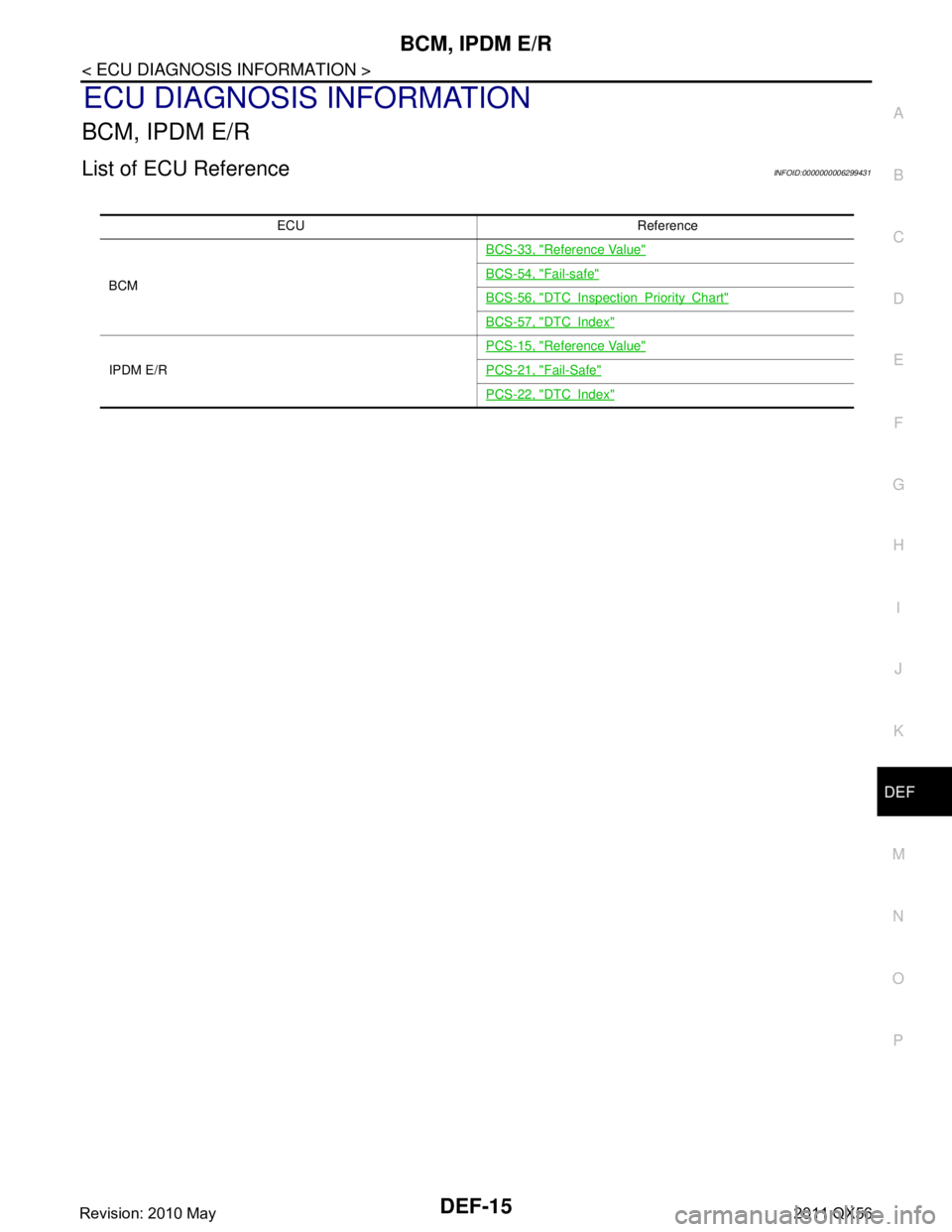
List of ECU ReferenceINFOID:0000000006299431
ECU Reference
BCM BCS-33, "
Reference Value"
BCS-54, "Fail-safe"
BCS-56, "DTCInspectionPriorityChart"
BCS-57, "DTCIndex"
IPDM E/R
PCS-15, "
Reference Value"
PCS-21, "Fail-Safe"
PCS-22, "DTCIndex"
Revision: 2010 May2011 QX56
Page 1537 of 5598

DLK-1
BODY EXTERIOR, DOORS, ROOF & VEHICLE SECURITY
C
D
E
F
G H
I
J
L
M
SECTION DLK
A
B
DLK
N
O P
CONTENTS
DOOR & LOCK
PRECAUTION ................ ...............................8
PRECAUTIONS .............................................. .....8
Precaution for Supplemental Restraint System
(SRS) "AIR BAG" and "SEAT BELT PRE-TEN-
SIONER" ............................................................. ......
8
Precaution Necessary for Steering Wheel Rota-
tion after Battery Disconnect .....................................
8
Precautions For Xenon Headlamp Service ...............9
Work ..........................................................................9
PREPARATION ...........................................10
PREPARATION .............................................. ....10
Commercial Service Tools .................................. ....10
SYSTEM DESCRIPTION .............................11
COMPONENT PARTS ................................... ....11
DOOR LOCK SYSTEM .............................................11
DOOR LOCK SYSTEM :
Component Parts Location ................................ ....
11
DOOR LOCK SYSTEM : Component Description ....12
AUTOMATIC BACK DOOR SYSTEM .......................13
AUTOMATIC BACK DOOR SYSTEM :
Component Parts Location ................................ ....
14
AUTOMATIC BACK DOOR SYSTEM :
Component Description ..........................................
15
SYSTEM (POWER DOOR LOCK SYSTEM) .....16
System Diagram .................................................. ....16
System Description .................................................16
SYSTEM (INTELLIGENT KEY SYSTEM) ..........18
INTELLIGENT KEY SYSTEM ...................................18
INTELLIGENT KEY SYSTEM : System Diagram ....18
INTELLIGENT KEY SYSTEM : System Descrip-
tion ..........................................................................
18
DOOR LOCK FUNCTION ...................................... ....19
DOOR LOCK FUNCTION : System Diagram ..........19
DOOR LOCK FUNCTION : System Description .....19
BACK DOOR OPEN FUNCTION ........................... ....21
BACK DOOR OPEN FUNCTION : System Dia-
gram ........................................................................
21
BACK DOOR OPEN FUNCTION : System De-
scription ...................................................................
21
REMOTE KEYLESS ENTRY FUNCTION ..................23
REMOTE KEYLESS ENTRY FUNCTION : Sys-
tem Diagram ........................................................ ....
23
REMOTE KEYLESS ENTRY FUNCTION : Sys-
tem Description ........................................................
23
KEY REMINDER FUNCTION ................................ ....25
KEY REMINDER FUNCTION : System Diagram ....25
KEY REMINDER FUNCTION : System Descrip-
tion ...........................................................................
26
WELCOME LIGHT FUNCTION ............................. ....26
WELCOME LIGHT FUNCTION : System Diagram
....
26
WELCOME LIGHT FUNCTION : System Descrip-
tion ...........................................................................
26
WARNING FUNCTION .......................................... ....27
WARNING FUNCTION : System Description ..........27
SYSTEM (AUTOMATIC BACK DOOR SYS-
TEM) ..................................................................
31
System Diagram .................................................. ....31
System Description ..................................................31
SYSTEM (INTEGRATED HOMELINK
TRANSMITTER) ................................................
37
System Description .............................................. ....37
DIAGNOSIS SYSTEM (BCM) ...........................38
COMMON ITEM ..................................................... ....38
COMMON ITEM : CONSULT-III Function (BCM -
COMMON ITEM) .....................................................
38
Revision: 2010 May2011 QX56
Page 1538 of 5598

DLK-2
DOOR LOCK .............................................................39
DOOR LOCK : CONSULT-III Function (BCM -
DOOR LOCK) .........................................................
39
INTELLIGENT KEY ................................................ ...40
INTELLIGENT KEY : CONSULT-III Function
(BCM - INTELLIGENT KEY) ...................................
41
TRUNK ................................................................... ...44
TRUNK : CONSULT-III Function (BCM - TRUNK) ...44
DIAGNOSIS SYSTEM (AUTOMATIC BACK
DOOR CONTROL UNIT) ...................................
45
CONSULT-III Function (AUTOMATIC BACK
DOOR CONTROL UNIT) ..................................... ...
45
ECU DIAGNOSIS INFORMATION ..............46
BCM ................................................................ ...46
List of ECU Reference ......................................... ...46
AUTOMATIC BACK DOOR CONTROL MOD-
ULE ....................................................................
47
Reference Value .................................................. ...47
Fail Safe .................................................................49
DTC Inspection Priority Chart ..............................49
DTC Index ..............................................................50
WIRING DIAGRAM .....................................51
DOOR & LOCK SYSTEM ............................... ...51
Wiring Diagram - DOOR & LOCK SYSTEM - ...... ...51
AUTOMATIC BACK DOOR SYSTEM ...............66
Wiring Diagram - AUTOMATIC BACK DOOR
SYSTEM - ............................................ ...................
66
INTEGRATED HOMELINK TRANSMITTER
SYSTEM ............ .............................................. ...
75
Wiring Diagram - INTEGRATED HOMELINK
TRANSMITTER SYSTEM - ....................................
75
BASIC INSPECTION ...... .............................77
DIAGNOSIS AND REPAIR WORK FLOW ..... ...77
Work Flow ............................................................ ...77
INSPECTION AND ADJUSTMENT ...................80
ADDITIONAL SERVICE WHEN REMOVING BAT-
TERY NEGATIVE TERMINAL ............................... ...
80
ADDITIONAL SERVICE WHEN REMOVING
BATTERY NEGATIVE TERMINAL : Description ....
80
ADDITIONAL SERVICE WHEN REMOVING
BATTERY NEGATIVE TERMINAL : Work Proce-
dure ........................................................................
80
ADDITIONAL SERVICE WHEN REPLACING
CONTROL UNIT (BCM) ......................................... ...
80
ADDITIONAL SERVICE WHEN REPLACING
CONTROL UNIT (BCM) : Description ....................
80
ADDITIONAL SERVICE WHEN REPLACING
CONTROL UNIT (BCM) : Work Procedure .......... ...
80
ADDITIONAL SERVICE WHEN REPLACING (AU-
TOMATIC BACK DOOR CONTROL MODULE) .......
80
ADDITIONAL SERVICE WHEN REPLACING
(AUTOMATIC BACK DOOR CONTROL MOD-
ULE) : Description ................................................ ...
80
ADDITIONAL SERVICE WHEN REPLACING
(AUTOMATIC BACK DOOR CONTROL MOD-
ULE) : Work Procedure ........................................ ...
80
DTC/CIRCUIT DIAGNOSIS ........................82
U1000 CAN COMM CIRCUIT ......................... ...82
Description ........................................................... ...82
DTC Logic ...............................................................82
Diagnosis Procedure ...............................................82
U1010 CONTROL UNIT (CAN) .........................83
DTC Logic ............................................................ ...83
Diagnosis Procedure ...............................................83
B2401 IGNITION POWER SUPPLY CIRCUIT ...84
DTC Logic ............................................................ ...84
Diagnosis Procedure ...............................................84
B2403 ENCODER ..............................................85
DTC Logic ............................................................ ...85
Diagnosis Procedure ...............................................85
B2409 HALF LATCH SWITCH ..........................86
DTC Logic ............................................................ ...86
Diagnosis Procedure ...............................................86
Component Inspection ............................................87
B2416 TOUCH SENSOR RH ............................88
DTC Logic ............................................................ ...88
Diagnosis Procedure ...............................................88
Component Inspection ............................................89
B2417 TOUCH SENSOR LH .............................90
DTC Logic ............................................................ ...90
Diagnosis Procedure ...............................................90
Component Inspection ............................................91
B2419 OPEN SWITCH ......................................92
DTC Logic ............................................................ ...92
Diagnosis Procedure ...............................................92
Component Inspection ............................................93
B2420 CLOSE SWITCH ....................................95
DTC Logic ............................................................ ...95
Diagnosis Procedure ...............................................95
Component Inspection ............................................96
B2421 CLUTCH OPERATION TIME .................97
DTC Logic ............................................................ ...97
Diagnosis Procedure ...............................................97
B2422 BACK DOOR STATE .............................98
DTC Logic ............................................................ ...98
Revision: 2010 May2011 QX56
Page 1545 of 5598

PRECAUTIONSDLK-9
< PRECAUTION >
C
DE
F
G H
I
J
L
M A
B
DLK
N
O P
5. When the repair work is completed, re-connect both battery cables. With the brake pedal released, turn
the push-button ignition switch from ACC position to ON position, then to LOCK position. (The steering
wheel will lock when the push-button ignition switch is turned to LOCK position.)
6. Perform self-diagnosis check of a ll control units using CONSULT-III.
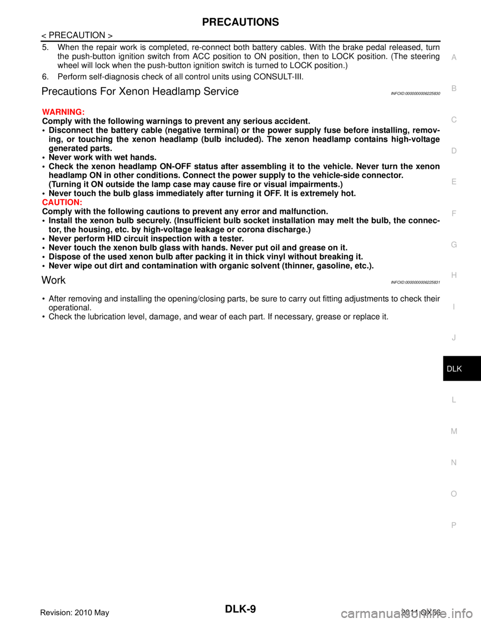
Precautions For Xenon Headlamp ServiceINFOID:0000000006225830
WARNING:
Comply with the follow ing warnings to prevent any serious accident.
Disconnect the battery cable (neg ative terminal) or the power supply fuse before installing, remov-
ing, or touching the xenon headlamp (bulb included). The xenon headlamp contains high-voltage
generated parts.
Never work with wet hands.
Check the xenon headlamp ON-OFF status after assem bling it to the vehicle. Never turn the xenon
headlamp ON in other conditions. Connect th e power supply to the vehicle-side connector.
(Turning it ON outside the lamp case m ay cause fire or visual impairments.)
Never touch the bulb glass immediately afte r turning it OFF. It is extremely hot.
CAUTION:
Comply with the follow ing cautions to prevent an y error and malfunction.
Install the xenon bulb securely. (I nsufficient bulb socket installation may melt the bulb, the connec-
tor, the housing, etc. by high-vol tage leakage or corona discharge.)
Never perform HID circuit inspection with a tester.
Never touch the xenon bulb glass with ha nds. Never put oil and grease on it.
Dispose of the used xenon bulb after p acking it in thick vinyl without breaking it.
Never wipe out dirt and cont amination with organic solven t (thinner, gasoline, etc.).
WorkINFOID:0000000006225831
After removing and installing the opening/closing parts, be sure to carry out fitting adjustments to check their
operational.
Check the lubrication level, damage, and wear of each part. If necessary, grease or replace it.
Revision: 2010 May2011 QX56
Page 1564 of 5598

DLK-28
< SYSTEM DESCRIPTION >
SYSTEM (INTELLIGENT KEY SYSTEM)
Take away warning
Door lock operation warning
Engine start information
Steering lock information
Intelligent Key low battery warning
Key ID warning
Key ID verification information
OPERATION CONDITION
Once the following condition from below is established, alert or warning is executed.
WARNING METHOD
The following table shows the alarm or warning methods with chime.
Warning/Information functions Operation procedure
Intelligent Key system malfunction When a malfun ction is detected on BCM, “KEY” warning lamp illuminates
OFF position warning For internal
Ignition switch: ACC position
Door switch (driver side
): ON (Door is open)
For external OFF position warning (For internal) is in active mode, driver side door is
closed
NOTE:
OFF position (For external) active only when each of the sequence occurs
as below: P position warning
→ ACC warning → OFF position warning (For
internal) → OFF position warning (For internal)
P position warning For internal
Shift position: Except P position
Engine is running to stopped (Ignition switch is ON to OFF)
For external Warning is activated when driver door is closed from the open position
while the P position warning (for inside vehicle) is ON
ACC warning When P position warning is in active mode, shift position changes P po-
sition
Ignition switch: ACC position
Ta k e a w a y w a r n i n g Door is open to close
Ignition switch: Except LOCK position
Door switch: ON to OFF (Door is open to close)
Intelligent Key cannot be detected inside the vehicle
Door is open Door switch: ON (Door is open)
Key ID verification every 5 seconds when registered Intelligent Key can-
not be detected inside the vehicle
Push-button ignition
switch operation Ignition switch: Except LOCK position
Press push-button ignition switch
Intelligent Key cannot be detected inside the vehicle
Door lock operation warning When door lock operation is requested while door lock operating condition
of door request switch or Intelligent Key are not satisfied
Engine start information Ignition switch is ON po-
sition
Ignition switch: ON position
Shift position: P position*
Engine is stopped
Ignition switch is except
ON position Ignition switch: Except ON position
Shift position: P position*
Intelligent Key is inserted in key slot or Intelligent Key can be detected
inside the vehicle
Steering lock information When steering lock cannot be released after ignition switch is turned ON
Intelligent Key low battery warning When Intelligent Key is low battery, BCM is detected after ignition switch is
turned ON
Key ID warning When registered Intelligent Key cannot be detected inside the vehicle after
ignition switch is turned ON
Key ID verification information When registered Intelligent Key cannot be detected inside the vehicle
Intelligent Key battery is discharged
When NATS antenna amp cannot be detected NATS ID
Revision: 2010 May2011 QX56
Page 1574 of 5598

DLK-38
< SYSTEM DESCRIPTION >
DIAGNOSIS SYSTEM (BCM)
DIAGNOSIS SYSTEM (BCM)
COMMON ITEM
COMMON ITEM : CONSULT-III Function (BCM - COMMON ITEM)INFOID:0000000006307583
APPLICATION ITEM
CONSULT-III performs the following functions via CAN communication with BCM.
SYSTEM APPLICATION
BCM can perform the following functions for each system.
NOTE:
It can perform the diagnosis modes except the following for all sub system selection items.
×: Applicable item
*: This item is indicated, but not used.
FREEZE FRAME DATA (FFD)
The BCM records the following vehicle condition at the time a particular DTC is detected, and displays on
CONSULT-III.
Diagnosis mode Function Description
Work Support Changes the setting for each system function.
Self Diagnostic Result Displays the diagnosis results judged by BCM. Refer to BCS-57, "
DTCIndex".
CAN Diag Support Monitor Monitors the reception status of CAN communication viewed from BCM. Refer to CONSULT-III opera-
tion manual.
Data Monitor The BCM input/output signals are displayed.
Active Test The signals used to activate ea ch device are forcibly supplied from BCM.
Ecu Identification The BCM part number is displayed.
Configuration Read and save the vehicle specification.
Write the vehicle specification when replacing BCM.
System Sub system selection item Diagnosis mode
Work Support Data Monitor Active Test
Door lock DOOR LOCK ×××
Rear window defogger REAR DEFOGGER ××
Warning chime BUZZER ××
Interior room lamp timer INT LAMP ×××
Exterior lamp HEAD LAMP ×××
Wiper and washer WIPER ×××
Turn signal and hazard warning lamps FLASHER ×××
— AIR CONDITONER* ××
Intelligent Key system
Engine start system INTELLIGENT KEY
×××
Combination switch COMB SW ×
Body control system BCM ×
IVIS IMMU ×××
Interior room lamp battery saver BATTERY SAVER ×××
Back door TRUNK ×
Vehicle security system THEFT ALM ×××
RAP system RETAINED PWR ×
Signal buffer system SIGNAL BUFFER ××
Revision: 2010 May2011 QX56
Page 1580 of 5598

DLK-44
< SYSTEM DESCRIPTION >
DIAGNOSIS SYSTEM (BCM)
TRUNK
TRUNK : CONSULT-III Function (BCM - TRUNK)INFOID:0000000006225857
DATA MONITOR
LCD This test is able to check meter display information
Engine start information displays when “BP N” on CONSULT-III screen is touched
Engine start information displays when “BP I” on CONSULT-III screen is touched
Key ID warning displays when “ID NG” on CONSULT-III screen is touched
Steering lock information displays when “ROTAT” on CONSULT-III screen is touched
P position warning displays when “SFT P” on CONSULT-III screen is touched
INSRT: This item is displayed, but cannot be monitored
BATT: This item is displayed, but cannot be monitored
Take away through window warning displays
when “NO KY” on CONSULT-III screen is
touched
Take away warning display when “OUTKEY” on CONSULT-III screen is touched
OFF position warning display when “LK WN” on CONSULT-III screen is touched
FLASHER This test is able to check security hazard lamp operation
The hazard lamps are activated after “LH/RH/Off” on CONSULT-III screen is touched
P RANGE This test is able to check A/T shift selector power supply
On: Operate
Off: Non-operation
ENGINE SW ILLUMI This test is able to check push-button ignition switch illumination operation
Push-ignition switch illumination illuminates when “ON” on CONSULT-III screen is touched
LOCK INDICATOR This test is able to check LOCK indicato
r (push-button ignition switch) operation
On: Operate
Off: Non-operation
ACC INDICATOR This test is able to check ACC indicator (push-button ignition switch) operation
On: Operate
Off: Non-operation
IGNITION ON IND This test is able to check ON indicator (push-button ignition switch) operation
On: Operate
Off: Non-operation
HORN This test is able to check horn operation
On: Operate
Off: Non-operation
TRUNK/BACK DOOR NOTE:
This item is displayed, but cannot be used
Test item Description
Monitor Item Contents
PUSH SW Indicates [On/Off] condition of push switch
UNLK SEN -DR Indicates [On/Off] condition of unlock sensor
VEH SPEED 1 Indicates [Km/h] condition of ve hicle speed signal from combination meter
TR/BD OPEN SW Indicates [On/Off] condition of back door opener switch
TRNK/HAT MNTR NOTE:
This item is displayed, but cannot be monitored
RKE-TR/BD NOTE:
This item is displayed, but cannot be monitored
Revision: 2010 May2011 QX56
Page 1581 of 5598

DIAGNOSIS SYSTEM (AUTOMATIC BACK DOOR CONTROL UNIT)
DLK-45
< SYSTEM DESCRIPTION >
C
D E
F
G H
I
J
L
M A
B
DLK
N
O P
DIAGNOSIS SYSTEM (AUTOMATIC BACK DOOR CONTROL UNIT)
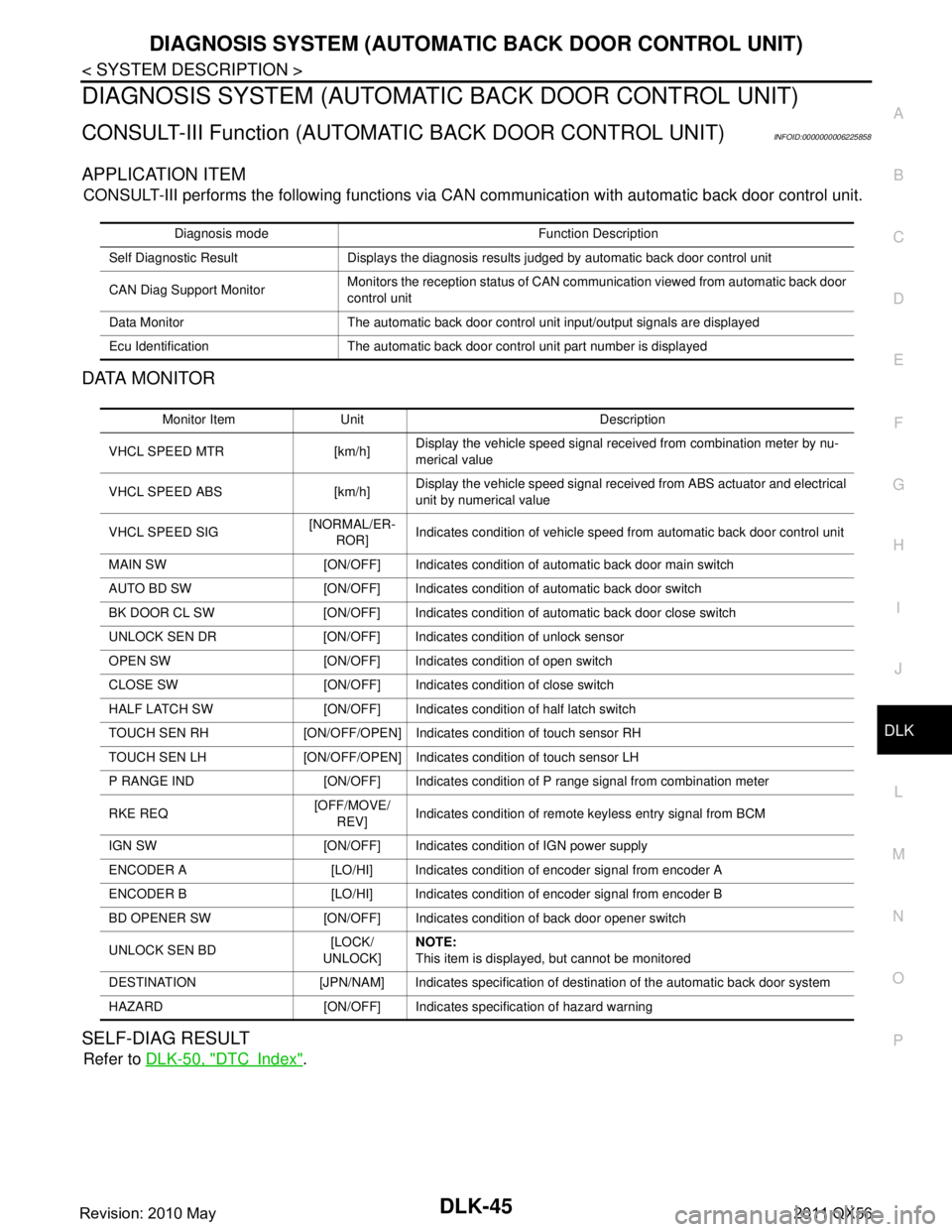
CONSULT-III Function (AUTOMATIC BACK DOOR CONTROL UNIT)INFOID:0000000006225858
APPLICATION ITEM
CONSULT-III performs the following functions via CA N communication with automatic back door control unit.
DATA MONITOR
SELF-DIAG RESULT
Refer to DLK-50, "DTCIndex".
Diagnosis mode Function Description
Self Diagnostic Result Displays the diagnosis results judged by automatic back door control unit
CAN Diag Support Monitor Monitors the reception status of CAN communication viewed from automatic back door
control unit
Data Monitor The automatic back door control unit input/output signals are displayed
Ecu Identification The automatic back door control unit part number is displayed
Monitor Item Unit Description
VHCL SPEED MTR [km/h] Display the vehicle speed signal received from combination meter by nu-
merical value
VHCL SPEED ABS [km/h] Display the vehicle speed
signal received from ABS actuator and electrical
unit by numerical value
VHCL SPEED SIG [NORMAL/ER-
ROR] Indicates condition of vehicle speed from automatic back door control unit
MAIN SW [ON/OFF] Indicates condition of automatic back door main switch
AUTO BD SW [ON/OFF] Indicates condition of automatic back door switch
BK DOOR CL SW [ON/OFF] Indicates condition of automatic back door close switch
UNLOCK SEN DR [ON/OFF] Indicates condition of unlock sensor
OPEN SW [ON/OFF] Indicates condition of open switch
CLOSE SW [ON/OFF] Indicates condition of close switch
HALF LATCH SW [ON/OFF] Indicates condition of half latch switch
TOUCH SEN RH [ON/OFF/OPEN] Indicates condition of touch sensor RH
TOUCH SEN LH [ON/OFF/OPEN] Indicates condition of touch sensor LH
P RANGE IND [ON/OFF] Indicates condition of P range signal from combination meter
RKE REQ [OFF/MOVE/
REV] Indicates condition of remote keyless entry signal from BCM
IGN SW [ON/OFF] Indicates condition of IGN power supply
ENCODER A [LO/HI] Indicates condition of encoder signal from encoder A
ENCODER B [LO/HI] Indicates condition of encoder signal from encoder B
BD OPENER SW [ON/OFF] Indicates condition of back door opener switch
UNLOCK SEN BD [LOCK/
UNLOCK] NOTE:
This item is displayed, but cannot be monitored
DESTINATION [JPN/NAM] Indicates specification of destination of the automatic back door system
HAZARD [ON/OFF] Indica tes specification of hazard warning
Revision: 2010 May2011 QX56