2011 INFINITI QX56 wheel
[x] Cancel search: wheelPage 2662 of 5598
EM-100
< UNIT REMOVAL AND INSTALLATION >
ENGINE ASSEMBLY
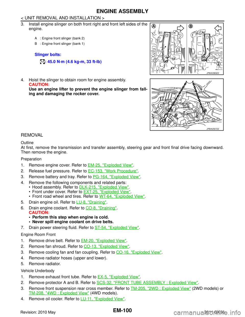
3. Install engine slinger on both front right and front left sides of theengine.
4. Hoist the slinger to obtain room for engine assembly. CAUTION:
Use an engine lifter to prevent the engine slinger from fall-
ing and damaging the rocker cover.
REMOVAL
Outline
At first, remove the transmission and transfer assemb ly, steering gear and front final drive facing downward.
Then remove the engine.
Preparation
1. Remove engine cover. Refer to EM-25, "Exploded View".
2. Release fuel pressure. Refer to EC-153, "
Work Procedure".
3. Remove battery and tray. Refer to PG-164, "
Exploded View".
4. Remove the following components and related parts: Hood assembly. Refer to DLK-215, "
Exploded View".
Front under cover. Refer to EXT-25, "
Exploded View".
Front road wheel and tires. Refer to WT-64, "
Exploded View".
5. Drain engine oil. Refer to LU-8, "
Draining".
6. Drain engine coolant. Refer to CO-8, "
Draining".
CAUTION:
Perform this step when engine is cold.
Never spill engine coolant on drive belts.
7. Drain power steering fluid. Refer to ST-54, "
Exploded View".
Engine Room Front
1. Remove drive belt. Refer to EM-20, "Exploded View".
2. Remove fan shroud. Refer to CO-13, "
Exploded View".
3. Remove cooling fan and fan coupling. Refer to CO-16, "
Exploded View".
4. Remove radiator hoses (upper and lower).
5. Remove radiator.
Vehicle Underbody
1. Remove exhaust front tube. Refer to EX-5, "Exploded View".
2. Remove protector A and B. Refer to SCS-32, "
FRONT TUBE ASSEMBLY : Exploded View".
3. Remove front suspension rear cross member. Refer to TM-205, "
2WD : Exploded View" (2WD models) or
TM-208, "
4WD : Exploded View" (4WD models).
4. Remove oil cooler. Refer to LU-11, "
Exploded View".
A : Engine front slinger (bank 2)
B : Engine front slinger (bank 1)
Slinger bolts:
: 45.0 N·m (4.6 kg-m, 33 ft-lb)
JPBIA3969ZZ
JPBIA2507ZZ
Revision: 2010 May2011 QX56
Page 2725 of 5598
![INFINITI QX56 2011 Factory Service Manual
SYSTEMEXL-15
< SYSTEM DESCRIPTION > [XENON TYPE]
C
D
E
F
G H
I
J
K
M A
B
EXL
N
O P
ACTIVE ADAPTIVE FRONT-LIGHTI NG SYSTEM : System DiagramINFOID:0000000006213899
ACTIVE ADAPTIVE FRONT-LIGHTING SYSTE INFINITI QX56 2011 Factory Service Manual
SYSTEMEXL-15
< SYSTEM DESCRIPTION > [XENON TYPE]
C
D
E
F
G H
I
J
K
M A
B
EXL
N
O P
ACTIVE ADAPTIVE FRONT-LIGHTI NG SYSTEM : System DiagramINFOID:0000000006213899
ACTIVE ADAPTIVE FRONT-LIGHTING SYSTE](/manual-img/42/57033/w960_57033-2724.png)
SYSTEMEXL-15
< SYSTEM DESCRIPTION > [XENON TYPE]
C
D
E
F
G H
I
J
K
M A
B
EXL
N
O P
ACTIVE ADAPTIVE FRONT-LIGHTI NG SYSTEM : System DiagramINFOID:0000000006213899
ACTIVE ADAPTIVE FRONT-LIGHTING SYSTEM : System DescriptionINFOID:0000000006213900
OUTLINE
AFS (ACTIVE ADAPTIVE FRONT-LIGHTING SY STEM) is controlled by AFS control unit.
AFS has AFS control (swivel control) and the headlamp auto aiming control.
- AFS control swivels the headlamp to the steering direction.
- Headlamp auto aiming control moves the headlamp light axis up/down according to the vehicle height.
AFS (ADAPTIVE FRONT-LIGHTING SYSTEM)
AFS Control Description
AFS control unit controls the headlamp (right) only when the steering wheel is turned rightward, and the
headlamp (left) only when the steering wheel is turned leftward.
AFS control unit detects the vehicle condition nec essary for AFS control with the following signals.
- AFS switch signal
- Vehicle speed signal (received from combination meter via CAN communication)
- Steering angle sensor signal (received from steering angle sensor via CAN communication)
- Shift position signal (received from TCM via CAN communication)
- Low beam status signal (received from IPDM E/R via CAN communication)
- Engine speed signal (received from ECM via CAN communication)
When the operation conditions are satisfied, AFS c ontrol unit controls the swivel angle depending on the
steering angle and the vehicle speed.
AFS operation condition- Swivel actuator initialization completed
- AFS “ON”(AFS OFF indicator lamp “OFF”)
- Headlamp ON
- While the engine running
- Selector lever position other than “P” or “R”
- Vehicle speed approximately 25 km/h (15.5 MPH) or more (Left swivel only; Right swivel activates regardless of the vehicle speed.)
Swivel Actuator Initialization
AFS control unit performs the swivel actuator in itialization when detecting that the engine starts.
JMLIA1077GB
Revision: 2010 May2011 QX56
Page 2790 of 5598
![INFINITI QX56 2011 Factory Service Manual
EXL-80
< DTC/CIRCUIT DIAGNOSIS >[XENON TYPE]
C0126 STEERING ANGLE SENSOR SIGNAL
C0126 STEERING ANGLE SENSOR SIGNAL
DTC LogicINFOID:0000000006213944
DTC DETECTION LOGIC
DTC CONFIRMATION PROCEDURE
1.DT INFINITI QX56 2011 Factory Service Manual
EXL-80
< DTC/CIRCUIT DIAGNOSIS >[XENON TYPE]
C0126 STEERING ANGLE SENSOR SIGNAL
C0126 STEERING ANGLE SENSOR SIGNAL
DTC LogicINFOID:0000000006213944
DTC DETECTION LOGIC
DTC CONFIRMATION PROCEDURE
1.DT](/manual-img/42/57033/w960_57033-2789.png)
EXL-80
< DTC/CIRCUIT DIAGNOSIS >[XENON TYPE]
C0126 STEERING ANGLE SENSOR SIGNAL
C0126 STEERING ANGLE SENSOR SIGNAL
DTC LogicINFOID:0000000006213944
DTC DETECTION LOGIC
DTC CONFIRMATION PROCEDURE
1.DTC ERASE
Erase the DTC memory of AFS with CONSULT-III.
>> GO TO 2.
2.DTC CONFIRMATION
1. Start the engine.
2. Turn the steering wheel to the maximum right/left.
3. Select the self-diagnosis with CONSULT-III.
4. Check the self-diagnosis result. Refer to EXL-39, "
DTC Index".
Is DTC
“C0126” detected?
YES >> Refer to EXL-80, "Diagnosis Procedure".
NO >> Refer to GI-40, "
Intermittent Incident".
Diagnosis ProcedureINFOID:0000000006213945
1.ABS ACTUATOR AND ELECTRICAL UNIT (CONTROL UNIT) SELF-DIAGNOSIS
Check the self-diagnosis result with CONSULT-III. C heck that ABS actuator and electrical unit (control unit)
does not detect any DTCs.
Is any DTC detected?
YES >> Check ABS actuator and electrical unit (control unit).Refer to BRC-51, "DTC Index".
NO >> GO TO 2.
2.DTC ERASE
Erase DTC memory of AFS with CONSULT-III.
Is the memory erased?
YES >> Inspection end.
NO >> Replace AFS control unit. Refer to EXL-135, "
Removal and Installation"
DTC No. Trouble diagnosis name DTC detection condition Possible causes
C0126 Steering angle sensor signal In any of the following conditions
The steering angle sensor signal
is not received.
The steering angle sensor signal error is received.
Out-of-standard signal (-900 °-
+900 °) is received. Steering angle sensor
AFS control unit
Revision: 2010 May2011 QX56
Page 2856 of 5598

EXT-1
BODY EXTERIOR, DOORS, ROOF & VEHICLE SECURITY
C
D
E
F
G H
I
J
L
M
SECTION EXT
A
B
EXT
N
O P
CONTENTS
EXTERIOR
PRECAUTION ................ ...............................3
PRECAUTIONS .............................................. .....3
Precaution for Supplemental Restraint System
(SRS) "AIR BAG" and "SEAT BELT PRE-TEN-
SIONER" ............................................................. ......
3
Precaution Necessary for Steering Wheel Rota-
tion after Battery Disconnect .....................................
3
Precaution for Procedure without Cowl Top Cover ......4
Precaution for Work ..................................................4
PREPARATION ............................................5
PREPARATION .............................................. .....5
Commercial Service Tools ................................. ......5
SYMPTOM DIAGNOSIS ...............................6
SQUEAK AND RATTLE TROUBLE DIAG-
NOSES ........................ ........................................
6
Work Flow ........................................................... ......6
Inspection Procedure ................................................8
Diagnostic Worksheet .............................................10
REMOVAL AND INSTALLATION ...............12
FRONT BUMPER ........................................... ....12
Exploded View .................................................... ....12
Removal and Installation .........................................13
REAR BUMPER .................................................16
Exploded View .................................................... ....16
Removal and Installation .........................................17
FRONT GRILLE .................................................19
Exploded View .................................................... ....19
Removal and Installation .........................................19
COWL TOP .........................................................21
Exploded View .................................................... ....21
Removal and Installation .........................................21
FENDER PROTECTOR ......................................23
FENDER PROTECTOR ......................................... ....23
FENDER PROTECTOR : Exploded View ...............23
FENDER PROTECTOR : Removal and Installa-
tion ...........................................................................
23
REAR WHEEL HOUSE PROTECTOR .................. ....23
REAR WHEEL HOUSE PROTECTOR : Exploded
View .........................................................................
24
REAR WHEEL HOUSE PROTECTOR : Removal
and Installation ........................................................
24
FLOOR SIDE FAIRING .....................................25
Exploded View .........................................................25
Removal and Installation .........................................25
OVER FENDER .................................................26
Exploded View .........................................................26
Removal and Installation .........................................26
ROOF RAIL .......................................................29
Exploded View .........................................................29
Removal and Installation .........................................29
ROOF SIDE MOLDING .....................................31
Exploded View .........................................................31
Removal and Installation .........................................31
DOOR OUTSIDE MOLDING .............................32
Exploded View .........................................................32
Removal and Installation .........................................32
DOOR PARTING SEAL ....................................34
Exploded View .........................................................34
Removal and Installation .........................................34
SILL MOLDING .................................................36
Exploded View .........................................................36
Removal and Installation .........................................36
DOOR SASH COVER .......................................37
Exploded View .........................................................37
Removal and Installation .........................................37
Revision: 2010 May2011 QX56
Page 2858 of 5598
PRECAUTIONSEXT-3
< PRECAUTION >
C
DE
F
G H
I
J
L
M A
B
EXT
N
O P
PRECAUTION
PRECAUTIONS
Precaution for Supplemental Restraint System (SRS) "AIR BAG" and "SEAT BELT
PRE-TENSIONER"
INFOID:0000000006367589
The Supplemental Restraint System such as “A IR BAG” and “SEAT BELT PRE-TENSIONER”, used along
with a front seat belt, helps to reduce the risk or severi ty of injury to the driver and front passenger for certain
types of collision. This system includes seat belt switch inputs and dual stage front air bag modules. The SRS
system uses the seat belt switches to determine the front air bag deployment, and may only deploy one front
air bag, depending on the severity of a collision and whether the front occupants are belted or unbelted.
Information necessary to service the system safely is included in the “SRS AIR BAG” and “SEAT BELT” of this
Service Manual.
WARNING:
• To avoid rendering the SRS inoper ative, which could increase the risk of personal injury or death in
the event of a collision that would result in air ba g inflation, all maintenance must be performed by
an authorized NISSAN/INFINITI dealer.
Improper maintenance, including in correct removal and installation of the SRS, can lead to personal
injury caused by unintentional act ivation of the system. For removal of Spiral Cable and Air Bag
Module, see the “SRS AIR BAG”.
Do not use electrical test equipm ent on any circuit related to the SRS unless instructed to in this
Service Manual. SRS wiring harnesses can be identi fied by yellow and/or orange harnesses or har-
ness connectors.
PRECAUTIONS WHEN USING POWER TOOLS (AIR OR ELECTRIC) AND HAMMERS
WARNING:
When working near the Air Bag Diagnosis Sensor Unit or other Air Bag System sensors with the
ignition ON or engine running, DO NOT use air or electric power tools or strike near the sensor(s)
with a hammer. Heavy vibration could activate the sensor(s) and deploy the air bag(s), possibly
causing serious injury.
When using air or electric power tools or hammers , always switch the ignition OFF, disconnect the
battery, and wait at least 3 minutes before performing any service.
Precaution Necessary for Steering Wh eel Rotation after Battery Disconnect
INFOID:0000000006367590
NOTE:
Before removing and installing any control units, first tu rn the push-button ignition switch to the LOCK posi-
tion, then disconnect both battery cables.
After finishing work, confirm that all control unit connectors are connected properly, then re-connect both
battery cables.
Always use CONSULT-III to perform self-diagnosis as a part of each function inspection after finishing work.
If a DTC is detected, perform trouble diagnos is according to self-diagnosis results.
For vehicle with steering lock unit, if the battery is disconnected or discharged, the steering wheel will lock and
cannot be turned.
If turning the steering wheel is required with the batte ry disconnected or discharged, follow the operation pro-
cedure below before starting the repair operation.
OPERATION PROCEDURE
1. Connect both battery cables. NOTE:
Supply power using jumper cables if battery is discharged.
2. Turn the push-button ignition switch to ACC position. (At this time, the steering lock will be released.)
3. Disconnect both battery cables. The steering lock wil l remain released with both battery cables discon-
nected and the steering wheel can be turned.
4. Perform the necessary repair operation.
Revision: 2010 May2011 QX56
Page 2859 of 5598
EXT-4
< PRECAUTION >
PRECAUTIONS
5. When the repair work is completed, re-connect both battery cables. With the brake pedal released, turn
the push-button ignition switch from ACC position to ON position, then to LOCK position. (The steering
wheel will lock when the push-button igniti on switch is turned to LOCK position.)
6. Perform self-diagnosis check of all control units using CONSULT-III.
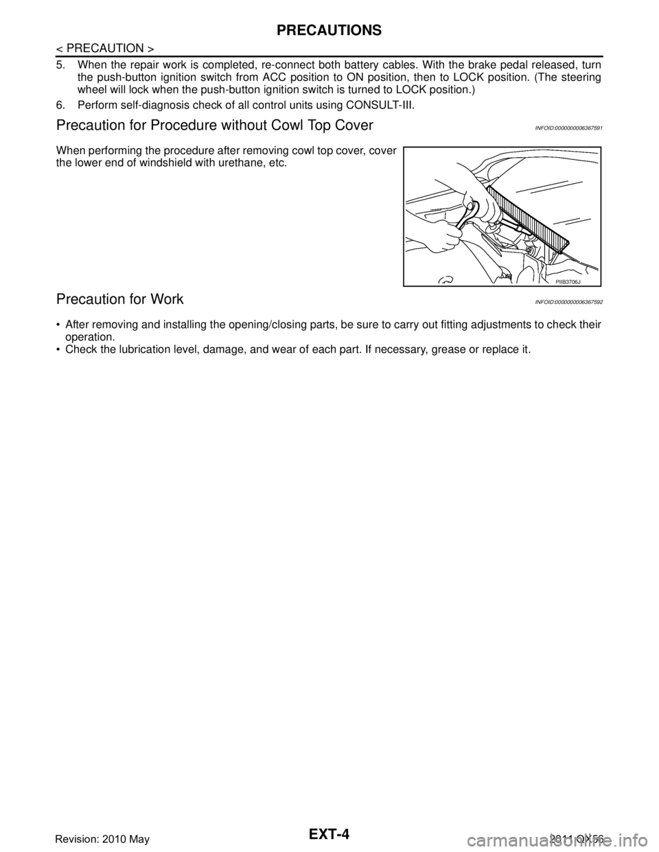
Precaution for Procedure without Cowl Top CoverINFOID:0000000006367591
When performing the procedure after removing cowl top cover, cover
the lower end of windshield with urethane, etc.
Precaution for WorkINFOID:0000000006367592
After removing and installing the opening/closing parts, be sure to carry out fitting adjustments to check their
operation.
Check the lubrication level, damage, and wear of each part. If necessary, grease or replace it.
PIIB3706J
Revision: 2010 May2011 QX56
Page 2878 of 5598
FENDER PROTECTOREXT-23
< REMOVAL AND INSTALLATION >
C
DE
F
G H
I
J
L
M A
B
EXT
N
O P
FENDER PROTECTOR
FENDER PROTECTOR
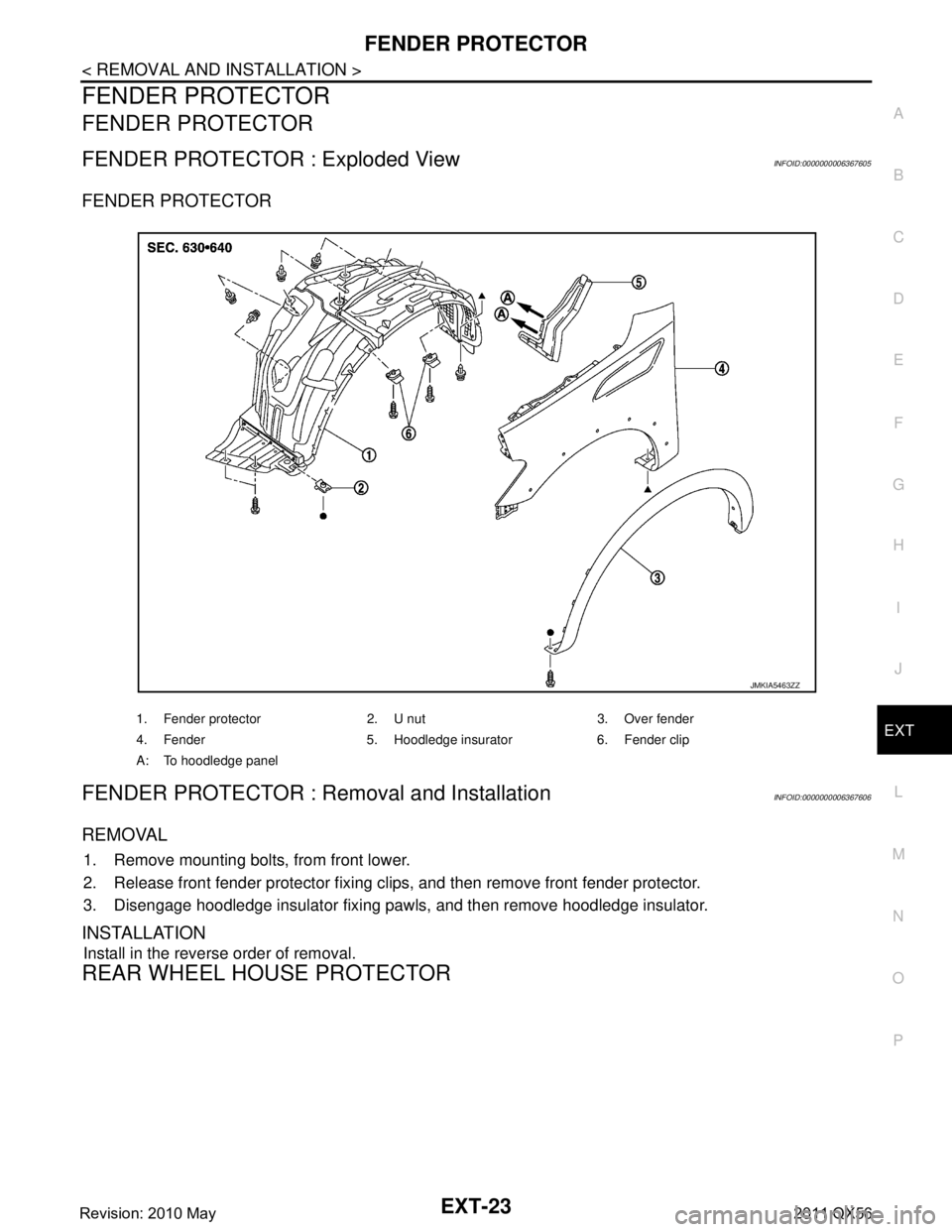
FENDER PROTECTOR : Exploded ViewINFOID:0000000006367605
FENDER PROTECTOR
FENDER PROTECTOR : Remo val and InstallationINFOID:0000000006367606
REMOVAL
1. Remove mounting bolts, from front lower.
2. Release front fender protector fixing clips, and then remove front fender protector.
3. Disengage hoodledge insulator fixing pawls, and then remove hoodledge insulator.
INSTALLATION
Install in the reverse order of removal.
REAR WHEEL HOUSE PROTECTOR
1. Fender protector 2. U nut 3. Over fender
4. Fender 5. Hoodledge insurator 6. Fender clip
A: To hoodledge panel
JMKIA5463ZZ
Revision: 2010 May2011 QX56
Page 2879 of 5598
EXT-24
< REMOVAL AND INSTALLATION >
FENDER PROTECTOR
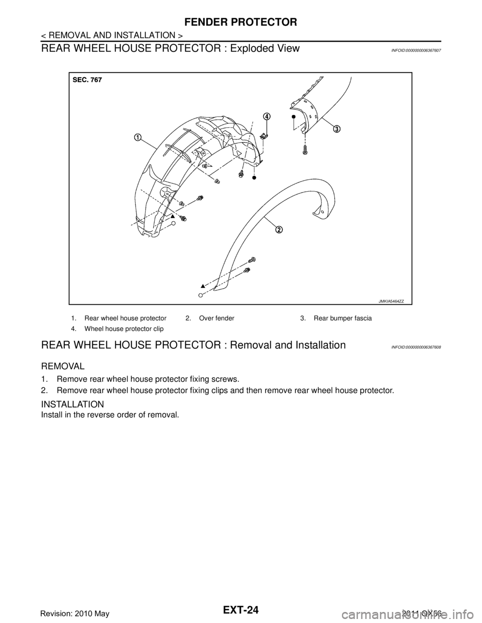
REAR WHEEL HOUSE PROTECTOR : Exploded View
INFOID:0000000006367607
REAR WHEEL HOUSE PROTECTOR : Removal and InstallationINFOID:0000000006367608
REMOVAL
1. Remove rear wheel house protector fixing screws.
2. Remove rear wheel house protector fixing c lips and then remove rear wheel house protector.
INSTALLATION
Install in the reverse order of removal.
1. Rear wheel house protector 2. Over fender 3. Rear bumper fascia
4. Wheel house protector clip
JMKIA5464ZZ
Revision: 2010 May2011 QX56