2011 INFINITI QX56 oil pressure
[x] Cancel search: oil pressurePage 4989 of 5598

ST-2
STEERING WHEEL ...........................................33
Exploded View ..................................................... ...33
Removal and Installation ........................................33
STEERING COLUMN ........................................34
Exploded View ..................................................... ...34
Removal and Installation ........................................34
Inspection ...............................................................35
STEERING SHAFT ............................................37
Exploded View ..................................................... ...37
Removal and Installation ........................................37
Inspection ...............................................................39
STEERING GEAR AND LINKAGE ....................41
Exploded View ..................................................... ...41
Removal and Installation ........................................42
Disassembly and Assembly ....................................43
Inspection ...............................................................46
POWER STEERING OIL PUMP ........................48
Exploded View ..................................................... ...48
Removal and Installation ........................................49
Disassembly and Assembly ....................................50
Inspection ...............................................................52
HYDRAULIC LINE .......................................... ...54
Exploded View ..................................................... ...54
HEATED STEERING WHEEL SWITCH ............56
Exploded View ..................................................... ...56
Removal and Installation .........................................56
SERVICE DATA AND SPECIFICATIONS
(SDS) .......... ................................................
57
SERVICE DATA AND SPECIFICATIONS
(SDS) .............................................................. ...
57
General Specifications ......................................... ...57
Steering Wheel Axial End Play and Play ................57
Steering Wheel Turning Force ................................57
Steering Angle ........................................................57
Steering Column Length .........................................57
Steering Column Mounting Dimensions ..................57
Steering Column Operating Range .........................57
Steering Shaft Sliding Range ..................................58
Rack Sliding Force ..................................................58
Rack Stroke ............................................................58
Socket Swing Force and Rotating Torque ..............58
Socket Axial End Play .............................................58
Inner Socket Length ................................................58
Relief Oil Pressure ..................................................58
Revision: 2010 May2011 QX56
Page 4992 of 5598
PREPARATIONST-5
< PREPARATION >
C
DE
F
H I
J
K L
M A
B
ST
N
O P
PREPARATION
PREPARATION
Special Service ToolsINFOID:0000000006225574
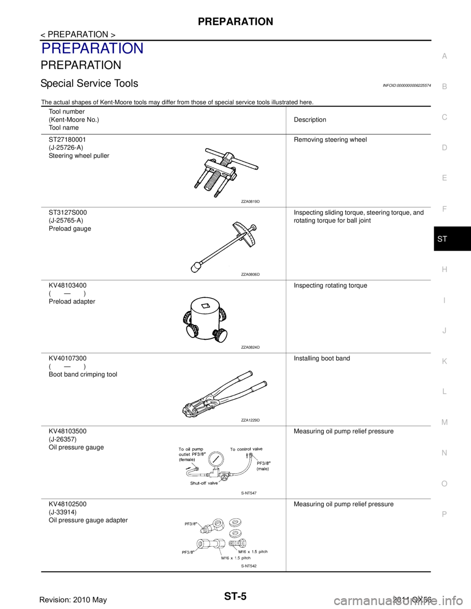
The actual shapes of Kent-Moore t ools may differ from those of special service tools illustrated here.
Tool number
(Kent-Moore No.)
Tool name Description
ST27180001
(J-25726-A)
Steering wheel puller Removing steering wheel
ST3127S000
(J-25765-A)
Preload gauge Inspecting sliding torque, steering torque, and
rotating torque for ball joint
KV48103400
(—)
Preload adapter Inspecting rotating torque
KV40107300
(—)
Boot band crimping tool Installing boot band
KV48103500
(J-26357)
Oil pressure gauge Measuring oil pump relief pressure
KV48102500
(J-33914)
Oil pressure gauge adapter Measuring oil pump relief pressure
ZZA0819D
ZZA0806D
ZZA0824D
ZZA1229D
S-NT547
S-NT542
Revision: 2010 May2011 QX56
Page 5001 of 5598
ST-14
< BASIC INSPECTION >
STEERING WHEEL
STEERING WHEEL
InspectionINFOID:0000000006225584
NEUTRAL POSITION STEERING WHEEL
1. Check that steering gear assembly, steering column assembly and steering wheel are installed in the cor-
rect position.
2. Perform neutral position inspection after wheel alignment. Refer to FSU-7, "
Inspection".
3. Set vehicle to the straight-ahead position and c onfirm steering wheel is in the neutral position.
4. Loosen outer socket lock nut and turn inner socket to left and right equally to make fine adjustments if steering wheel is not in the neutral position.
STEERING WHEEL TURNING FORCE
1. Park vehicle on a level and dry surface, set parking brake.
2. Tires need to be inflated the specified pressure. Refer to WT-69, "
Tire Air Pressure".
3. Start the engine.
4. Bring power steering fluid up to adequate operating temperature.
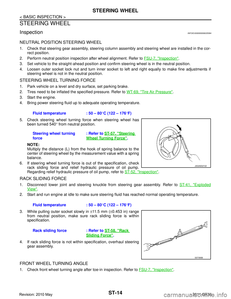
5. Check steering wheel turning force when steering wheel has been turned 540 ° from neutral position.
NOTE:
Multiply the distance (L) from the hook of spring balance to the
center of steering wheel by the measurement value with a spring
balance.
6. If steering wheel turning force is out of the specification, check
rack sliding force and relief hydraulic pressure of oil pump.
Regarding relief hydraulic pressure of oil pump, refer to ST-52, "
Inspection".
RACK SLIDING FORCE
1. Disconnect lower joint and steering knuckle from steering gear assembly. Refer to ST-41, "Exploded
View".
2. Start and run engine at idle to make sure steer ing fluid has reached normal operating temperature.
3. While pulling outer socket slowly in ±11.5 mm ( ±0.453 in) range
from neutral position, make sure rack sliding force is within
specification.
4. If rack sliding force is not within specification, overhaul steering gear assembly.
FRONT WHEEL TURNING ANGLE
1. Check front wheel turning angle after toe-in inspection. Refer to FSU-7, "Inspection".
Fluid temperature : 50 – 80
°C (122 – 176 °F)
Steering wheel turning
force : Refer to
ST-57, "
Steering
Wheel Turning Force".
JSGIA0027ZZ
Fluid temperature : 50 – 80 °C (122 – 176 °F)
Rack sliding force : Refer to ST-58, "
Rack
Sliding Force".
SST090B
Revision: 2010 May2011 QX56
Page 5037 of 5598
ST-50
< REMOVAL AND INSTALLATION >
POWER STEERING OIL PUMP
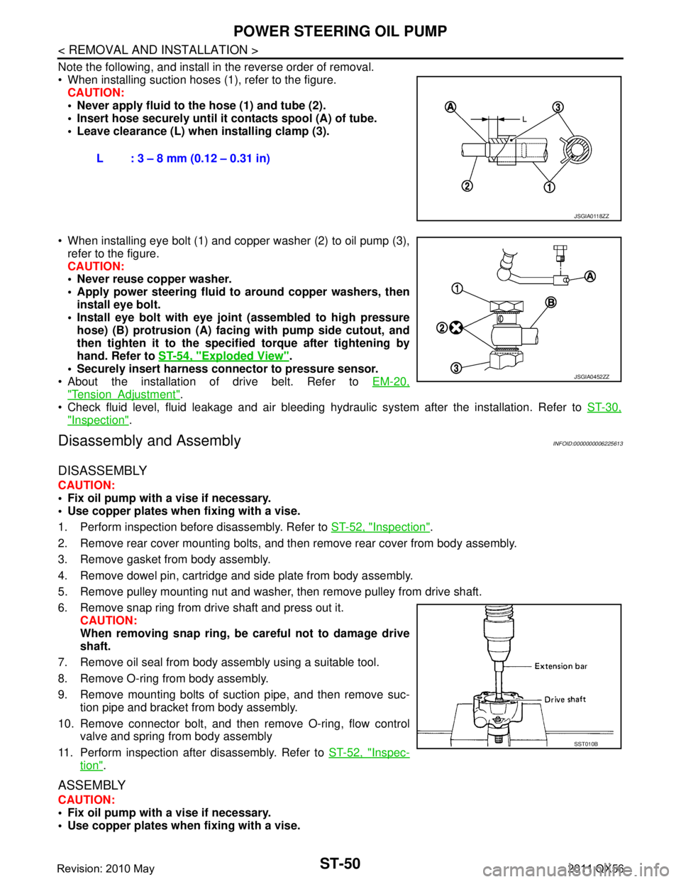
Note the following, and install in the reverse order of removal.
When installing suction hoses (1), refer to the figure.CAUTION:
Never apply fluid to the hose (1) and tube (2).
Insert hose securely until it contacts spool (A) of tube.
Leave clearance (L) when installing clamp (3).
When installing eye bolt (1) and copper washer (2) to oil pump (3), refer to the figure.
CAUTION:
Never reuse copper washer.
Apply power steering fluid to around copper washers, then
install eye bolt.
Install eye bolt with eye join t (assembled to high pressure
hose) (B) protrusion (A) facing with pump side cutout, and
then tighten it to the specifi ed torque after tightening by
hand. Refer to ST-54, "
Exploded View".
Securely insert harness connector to pressure sensor.
About the installation of drive belt. Refer to EM-20,
"TensionAdjustment".
Check fluid level, fluid leakage and air bleeding hydr aulic system after the installation. Refer to ST-30,
"Inspection".
Disassembly and AssemblyINFOID:0000000006225613
DISASSEMBLY
CAUTION:
Fix oil pump with a vise if necessary.
Use copper plates when fixing with a vise.
1. Perform inspection before disassembly. Refer to ST-52, "
Inspection".
2. Remove rear cover mounting bolts, and then remove rear cover from body assembly.
3. Remove gasket from body assembly.
4. Remove dowel pin, cartridge and side plate from body assembly.
5. Remove pulley mounting nut and washer, then remove pulley from drive shaft.
6. Remove snap ring from drive shaft and press out it. CAUTION:
When removing snap ring, be careful not to damage drive
shaft.
7. Remove oil seal from body assembly using a suitable tool.
8. Remove O-ring from body assembly.
9. Remove mounting bolts of suction pipe, and then remove suc- tion pipe and bracket from body assembly.
10. Remove connector bolt, and then remove O-ring, flow control
valve and spring from body assembly
11. Perform inspection after disassembly. Refer to ST-52, "
Inspec-
tion".
ASSEMBLY
CAUTION:
Fix oil pump with a vise if necessary.
Use copper plates when fixing with a vise.L : 3 – 8 mm (0.12 – 0.31 in)
JSGIA0118ZZ
JSGIA0452ZZ
SST010B
Revision: 2010 May2011 QX56
Page 5039 of 5598
ST-52
< REMOVAL AND INSTALLATION >
POWER STEERING OIL PUMP
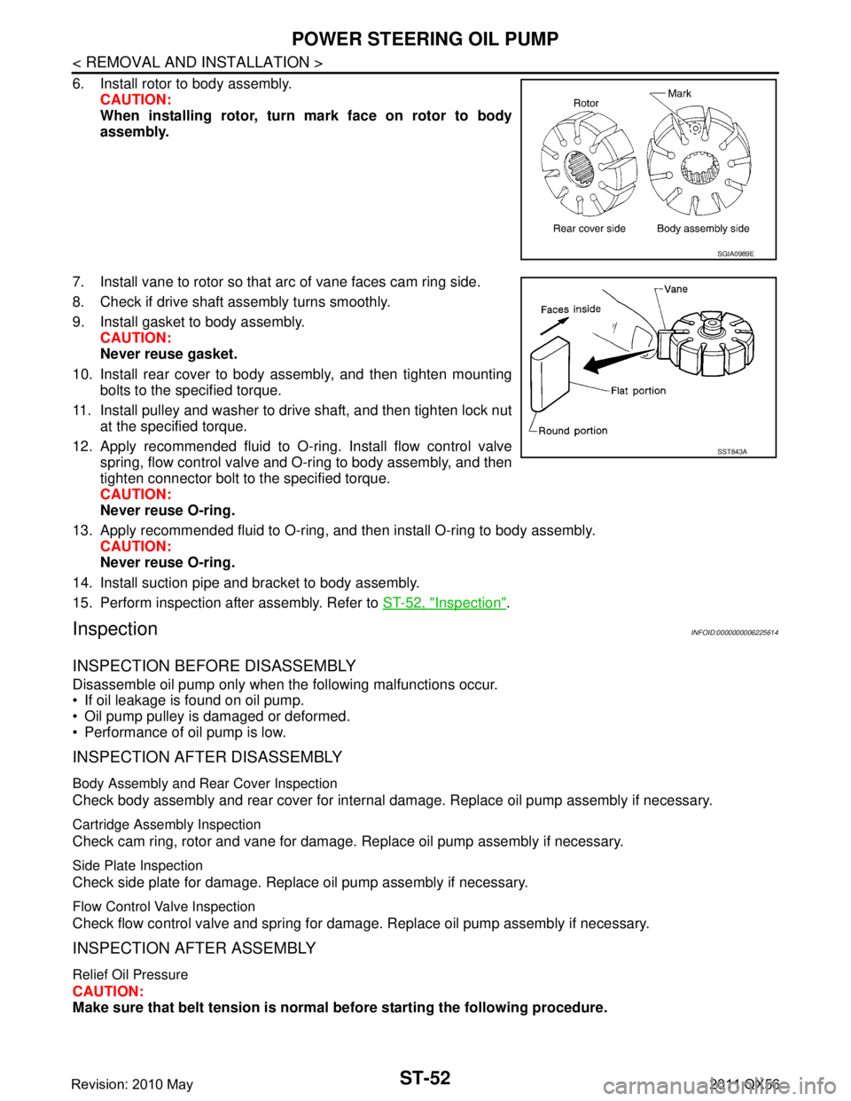
6. Install rotor to body assembly.CAUTION:
When installing rotor, turn mark face on rotor to body
assembly.
7. Install vane to rotor so that arc of vane faces cam ring side.
8. Check if drive shaft assembly turns smoothly.
9. Install gasket to body assembly. CAUTION:
Never reuse gasket.
10. Install rear cover to body assembly, and then tighten mounting bolts to the specified torque.
11. Install pulley and washer to drive shaft, and then tighten lock nut at the specified torque.
12. Apply recommended fluid to O-ring. Install flow control valve spring, flow control valve and O-ring to body assembly, and then
tighten connector bolt to the specified torque.
CAUTION:
Never reuse O-ring.
13. Apply recommended fluid to O-ring, and then install O-ring to body assembly. CAUTION:
Never reuse O-ring.
14. Install suction pipe and bracket to body assembly.
15. Perform inspection after assembly. Refer to ST-52, "
Inspection".
InspectionINFOID:0000000006225614
INSPECTION BEFORE DISASSEMBLY
Disassemble oil pump only when the following malfunctions occur.
If oil leakage is found on oil pump.
Oil pump pulley is damaged or deformed.
Performance of oil pump is low.
INSPECTION AFTER DISASSEMBLY
Body Assembly and Rear Cover Inspection
Check body assembly and rear cover for internal damage. Replace oil pump assembly if necessary.
Cartridge Assembly Inspection
Check cam ring, rotor and vane for damage. Replace oil pump assembly if necessary.
Side Plate Inspection
Check side plate for damage. Replace oil pump assembly if necessary.
Flow Control Valve Inspection
Check flow control valve and spring for damage. Replace oil pump assembly if necessary.
INSPECTION AFTER ASSEMBLY
Relief Oil Pressure
CAUTION:
Make sure that belt tension is normal before starting the following procedure.
SGIA0989E
SST843A
Revision: 2010 May2011 QX56
Page 5040 of 5598
![INFINITI QX56 2011 Factory Service Manual
POWER STEERING OIL PUMPST-53
< REMOVAL AND INSTALLATION >
C
DE
F
H I
J
K L
M A
B
ST
N
O P
1. Connect the oil pressure gauge [SST: KV48103500 (J-26357)] and the oil pressure gauge adapter [SST: KV4810 INFINITI QX56 2011 Factory Service Manual
POWER STEERING OIL PUMPST-53
< REMOVAL AND INSTALLATION >
C
DE
F
H I
J
K L
M A
B
ST
N
O P
1. Connect the oil pressure gauge [SST: KV48103500 (J-26357)] and the oil pressure gauge adapter [SST: KV4810](/manual-img/42/57033/w960_57033-5039.png)
POWER STEERING OIL PUMPST-53
< REMOVAL AND INSTALLATION >
C
DE
F
H I
J
K L
M A
B
ST
N
O P
1. Connect the oil pressure gauge [SST: KV48103500 (J-26357)] and the oil pressure gauge adapter [SST: KV48102500 (J-
33914)] between oil pump discharge connector and high-pres-
sure hose. Bleed air from the hydraulic circuit while opening
valve fully. Refer to ST-30, "
Inspection".
2. Start engine. Run engine until oil temperature reaches 50 to 80°C (122 to 176 °F).
CAUTION:
Leave the valve of the oil pressure gauge fully open while
starting and running engine. If engine is started with the
valve closed, the hydraulic pressure in oil pump goes up
to the relief pressure along with unusual increase of oil
temperature.
Be sure to keep hose clear of belts and other parts when engine is started.
3. Fully close the oil pressure gauge valve with engine at idle and measure the relief oil pressure.
CAUTION:
Never keep valve closed for 10 seconds or longer.
4. Open the valve slowly after measuring. Repair oil pump if the relief oil pressure is outside the standard. Refer to ST-50, "
Disassembly and Assembly".
5. Disconnect the oil pressure gauge from hydraulic circuit.
6. When installing eye bolt (1) and copper washer (2) to oil pump (3), refer to the figure.
CAUTION:
Never reuse copper washers.
Apply power steering fluid to around copper washer, theninstall eye bolt.
Install eye bolt with eye join t (assembled to high pressure
hose) (B) protrusion (A) facing with pump side cutout, and
then tighten it to the specifi ed torque after tightening by
hand. Refer to ST-54, "
Exploded View".
Securely insert harness connector to pressure sensor.
7. Check fluid level, fluid leakage and air bleeding hydraulic sys- tem after the installation. Refer to ST-30, "
Inspection".
Relief oil pressure : Refer to
ST-58, "
Relief Oil Pres-
sure".
SGIA1225E
JSGIA0452ZZ
Revision: 2010 May2011 QX56
Page 5041 of 5598
ST-54
< REMOVAL AND INSTALLATION >
HYDRAULIC LINE
HYDRAULIC LINE
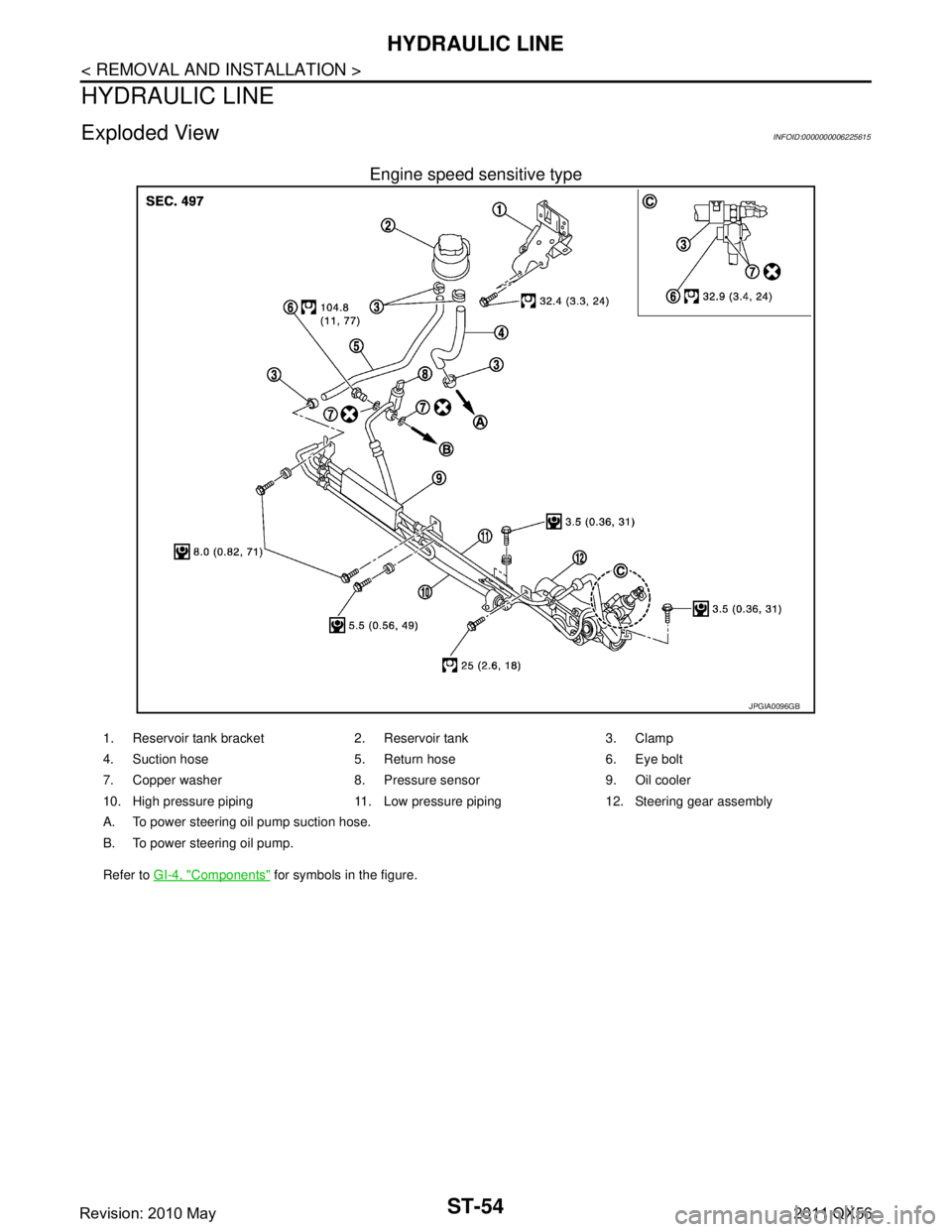
Exploded ViewINFOID:0000000006225615
Engine speed sensitive type
JPGIA0096GB
1. Reservoir tank bracket 2. Reservoir tank 3. Clamp
4. Suction hose 5. Return hose 6. Eye bolt
7. Copper washer 8. Pressure sensor 9. Oil cooler
10. High pressure piping 11. Low pressure piping 12. Steering gear assembly
A. To power steering oil pump suction hose.
B. To power steering oil pump.
Refer to GI-4, "
Components" for symbols in the figure.
Revision: 2010 May2011 QX56
Page 5042 of 5598
HYDRAULIC LINEST-55
< REMOVAL AND INSTALLATION >
C
DE
F
H I
J
K L
M A
B
ST
N
O P
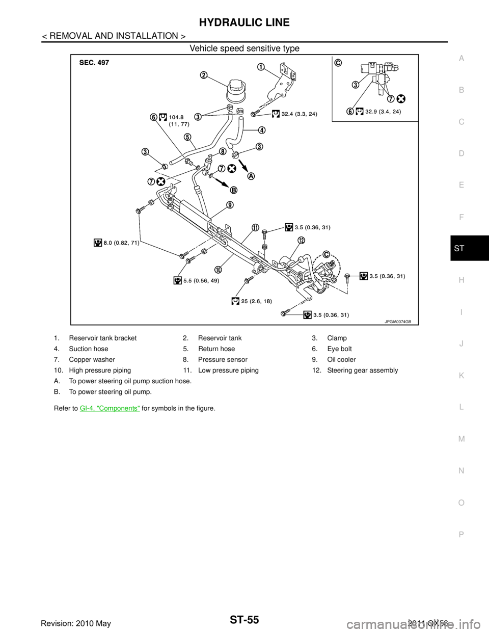
Vehicle speed sensitive type
JPGIA0074GB
1. Reservoir tank bracket 2. Reservoir tank 3. Clamp
4. Suction hose 5. Return hose 6. Eye bolt
7. Copper washer 8. Pressure sensor 9. Oil cooler
10. High pressure piping 11. Low pressure piping 12. Steering gear assembly
A. To power steering oil pump suction hose.
B. To power steering oil pump.
Refer to GI-4, "
Components" for symbols in the figure.
Revision: 2010 May2011 QX56