2011 INFINITI QX56 towing
[x] Cancel search: towingPage 1382 of 5598
![INFINITI QX56 2011 Factory Service Manual
DAS
HANDLING PRECAUTIONDAS-417
< SYSTEM DESCRIPTION > [BSW]
C
D
E
F
G H
I
J
K L
M B
N P A
HANDLING PRECAUTION
Precautions for Blind Spot WarningINFOID:0000000006223856
SIDE RADAR HANDLING
Side rada INFINITI QX56 2011 Factory Service Manual
DAS
HANDLING PRECAUTIONDAS-417
< SYSTEM DESCRIPTION > [BSW]
C
D
E
F
G H
I
J
K L
M B
N P A
HANDLING PRECAUTION
Precautions for Blind Spot WarningINFOID:0000000006223856
SIDE RADAR HANDLING
Side rada](/manual-img/42/57033/w960_57033-1381.png)
DAS
HANDLING PRECAUTIONDAS-417
< SYSTEM DESCRIPTION > [BSW]
C
D
E
F
G H
I
J
K L
M B
N P A
HANDLING PRECAUTION
Precautions for Blind Spot WarningINFOID:0000000006223856
SIDE RADAR HANDLING
Side radar for BSW system is located inside the rear bumper.
Always keep the rear bumper near the side radar clean.
Do not attach a sticker (including transparent material), install an accessory or paintwork near the side radar.
Do not strike or damage the areas around the side radar.
Do not strike, damage, and scratch the side radar, especially the vent seal (gray circular) area, under repair.
PRECAUTIONS FOR BLIND SPOT WARNING
The BSW system is not a replacement for proper driving procedure and are not designed to prevent contact
with vehicles or objects. When changing lanes, always us e the side and rear mirrors and turn and look in the
direction driver will move to ensure it is safe to change lanes. Never rely solely on the BSW system.
The BSW system may not provide a warning for v ehicles that pass through the detection zone quickly.
Do not use the BSW system when towing a trai ler because the system may not function properly.
Excessive noise (e.g. audio system volume, open vehicle window) will interfere with the chime sound, and it may not be heard.
The side radar may not be able to detect and activate BSW when certain objects are present such as:
- Pedestrians, bicycles, animals.
- Several types of vehicles such as motorcycles.
- Oncoming vehicles.
- Vehicles remaining in the detection z one when driver accelerate from a stop.
- A vehicle merging into an adjacent lane at a speed approximately the same as vehicle.
- A vehicle approaching rapidly from behind.
- A vehicle which vehicle overtakes rapidly.
Severe weather or road spray conditions may reduce t he ability of the side radar to detect other vehicles.
The side radar detection zone is designed based on a standard lane width. When driving in a wider lane, the
side radar may not detect vehicles in an adjacent lane. When driving in a narrow lane, the side radar may
detect vehicles driving two lanes away.
The side radar are designed to ignore most stationary objects, however objects such as guardrails, walls,
foliage and parked vehicles may occasionally be det ected. This is a normal operating condition.
Revision: 2010 May2011 QX56
Page 1487 of 5598
![INFINITI QX56 2011 Factory Service Manual
DAS-522
< SYMPTOM DIAGNOSIS >[BSW]
NORMAL OPERATING CONDITION
NORMAL OPERATING CONDITION
DescriptionINFOID:0000000006223980
PRECAUTIONS FOR BLIND SPOT WARNING (BSW)
The BSW system is not a replacem INFINITI QX56 2011 Factory Service Manual
DAS-522
< SYMPTOM DIAGNOSIS >[BSW]
NORMAL OPERATING CONDITION
NORMAL OPERATING CONDITION
DescriptionINFOID:0000000006223980
PRECAUTIONS FOR BLIND SPOT WARNING (BSW)
The BSW system is not a replacem](/manual-img/42/57033/w960_57033-1486.png)
DAS-522
< SYMPTOM DIAGNOSIS >[BSW]
NORMAL OPERATING CONDITION
NORMAL OPERATING CONDITION
DescriptionINFOID:0000000006223980
PRECAUTIONS FOR BLIND SPOT WARNING (BSW)
The BSW system is not a replacement for proper dr
iving procedure and are not designed to prevent contact
with vehicles or objects. When changing lanes, always us e the side and rear mirrors and turn and look in the
direction driver will move to ensure it is safe to change lanes. Never rely solely on the BSW system.
The BSW system may not provide a warning for vehi cles that pass through the detection zone quickly.
Do not use the BSW system when towing a traile r because the system may not function properly.
Excessive noise (e.g. audio system volume, open vehi cle window) will interfere with the chime sound, and it
may not be heard.
The side radar may not be able to detect and activate BSW when certain objects are present such as:
- Pedestrians, bicycles, animals.
- Several types of vehicles such as motorcycles.
- Oncoming vehicles.
- Vehicles remaining in the detection z one when driver accelerate from a stop.
- A vehicle merging into an adjacent lane at a speed approximately the same as vehicle.
- A vehicle approaching rapidly from behind.
- A vehicle which vehicle overtakes rapidly.
Severe weather or road spray conditions may reduce t he ability of the side radar to detect other vehicles.
The side radar detection zone is designed based on a standard lane width. When driving in a wider lane, the
side radar may not detect vehicles in an adjacent l ane. When driving in a narrow lane, the side radar may
detect vehicles driving two lanes away.
The side radar are designed to ignore most stationary objects, however objects such as guardrails, walls,
foliage and parked vehicles may occasionally be detected. This is a normal operating condition.
Revision: 2010 May2011 QX56
Page 1788 of 5598
DLK-252
< REMOVAL AND INSTALLATION >
CAB MOUNTING INSULATOR
Drain brake fluid from brake line. Refer to BR-10, "Draining".
Release fuel pressure. Refer to EC-153, "
Work Procedure".
Disconnect both battery cables. Refer to PG-164, "
Removal and Installation".
Drain engine coolant from radiator. Refer to CO-8, "
Draining".
Discharge refrigerant from A/C circuit. Refer to HA-20, "
Recycle Refrigerant".
Drain power steering fluid from reservoir tank.
4. Remove parts relating to connection of body assembly and frame assembly. Tire and wheel: Refer to WT-64, "
Removal and Installation" (with TPMS).
Front fender protector (LH and RH): Refer to EXT-23, "
FENDER PROTECTOR : Removal and Installa-
tion".
Front bumper: Refer to EXT-13, "
Removal and Installation".
Radiator core support upper: Refer to DLK-220, "
Removal and Installation".
Fan shroud: Refer to CO-16, "
Removal and Installation".
Battery and battery case: Refer to PG-164, "
Removal and Installation".
Air cleaner case (upper and lower): Refer to EM-27, "
Removal and Installation".
Engine cover: Refer to EM-25, "
Removal and Installation".
Rear wheel house protector (LH and RH): EXT-24, "
REAR WHEEL HOUSE PROTECTOR : Removal
and Installation".
Rear bumper: Refer to EXT-17, "
Removal and Installation".
Fuel filler tube: Remove to FL-8, "
Exploded View".
Spare tire
Towing hook bracket.
5. Separate parts relating to connection of body assembly and frame assembly. Vehicle front
Disconnect ICC sensor connector. (models with ICC) Refer to CCS-176, "
Removal and Installation".
Remove radiator upper hose and radiator lower hose from radiator assembly. Refer to CO-13,
"Exploded View".
Remove A/T fluid cooler hose B and A/T fluid cooler hose E from A/T fluid cooler tubes. Refer to TM-
202, "Exploded View".
Remove power steering return hose from oil cooler, and then power steering return hose clamp bolt from frame assembly. Refer to ST-54, "
Exploded View".
Remove power steering suction hose from reservoir tank. Refer to ST-54, "
Exploded View".
CAUTION:
Never spill power steering fluid in engine room.
Remove A/C low-presser flexible hose from A/C low-presser pipe. Refer to HA-35, "
LOW-PRESSURE
FLEXIBLE HOSE : Removal and Installation".
Remove A/C hi-presser flexible hose from condenser. Refer to HA-34, "
HIGH-PRESSURE FLEXIBLE
HOSE : Removal and Installation".
Remove all engine Control Harness connectors, har ness clips and others that are connected to the
body assembly side of the engine room. (engine room LH and RH side). Refer to PG-148, "
Engine Con-
trol Harness".
NOTE:
Separate harness connectors from ECM (engine control module). Refer to EC-10, "
General Precau-
tions".
CAUTION:
When pulling out harnesses, never damage harnesses or connectors.
After temporarily securing connectors, cover th em with vinyl or similar material to protect
against adhesion of foreign materials.
Disconnect engine room harness connectors and remo ve harness clips from engine assembly (engine
RH side). Refer to PG-146, "
Engine Room Harness".
Remove heater hoses from front water outlet tube (engine room RH side). Refer to HA-33, "
Exploded
View".
Disconnect front wheel sensor connectors (LH and RH). Refer to BRC-134, "
FRONT WHEEL SENSOR
: Exploded View".
Disconnect fuel feed tube and EVAP hos e (front wheel well LH side).
Remove steering lower shaft from steering gear side assembly. Refer to ST-37, "
Removal and Installa-
tion"
CAUTION:
Spiral cable may be cut if steering wheel turns while separating steering column assembly and
steering gear assembly.
Revision: 2010 May2011 QX56
Page 2965 of 5598
GI-1
GENERAL INFORMATION
C
DE
F
G H
I
J
K L
M B
GI
SECTION GI
N
O P
CONTENTS
GENERAL INFORMATION
HOW TO USE THIS MANU AL ......................3
HOW TO USE THIS MANUAL ....................... .....3
Description .......................................................... ......3
Terms ........................................................................3
Units ..........................................................................3
Contents ....................................................................3
Relation between Illustrations and Descriptions .......4
Components ..............................................................4
HOW TO FOLLOW TROUBLE DIAGNOSES .....6
Description ................................................................6
How to Follow Test Groups in Trouble Diagnosis ......6
Key to Symbols Signifying Measurements or Pro-
cedures ............................................................... ......
7
HOW TO READ WIRING DIAGRAMS ................9
Connector Symbols ............................................. ......9
Sample/Wiring Diagram -Example- .........................10
Connector Information .............................................12
ABBREVIATIONS .......................................... ....14
Abbreviation List .................................................. ....14
TIGHTENING TORQUE OF STANDARD
BOLTS ................................................................
19
Description .......................................................... ....19
Tightening Torque Table (New Standard Includ-
ed) ...........................................................................
19
RECOMMENDED CHEMICAL PRODUCTS
AND SEALANTS ................................................
22
Recommended Chemical Products and Sealants ....22
VEHICLE INFORMATION ............................23
IDENTIFICATION INFORMATION ................. ....23
Model Variation ................................................... ....23
Information About Identification or Model Code ......23
Dimensions .............................................................25
Wheels & Tires ........................................................25
PRECAUTION ..............................................26
PRECAUTIONS .................................................26
Description ........................................................... ....26
Precaution for Supplemental Restraint System
(SRS) "AIR BAG" and "SEAT BELT PRE-TEN-
SIONER" .................................................................
26
Precautions For Xenon Headlamp Service .............26
Precaution Necessary for Steering Wheel Rota-
tion after Battery Disconnect ...................................
27
Precaution for Procedure without Cowl Top Cover ....27
General Precautions ................................................27
Three Way Catalyst .................................................29
Multiport Fuel Injection System or Engine Control
System .....................................................................
29
Hoses ......................................................................29
Engine Oils ..............................................................30
Air Conditioning .......................................................31
Fuel ..........................................................................31
LIFTING POINT .................................................32
Pantograph Jack ......................................................32
Garage Jack and Safety Stand ................................32
2-Pole Lift ................................................................33
TOW TRUCK TOWING .....................................34
Tow Truck Towing ...................................................34
Vehicle Recovery (Freeing a Stuck Vehicle) ...........34
BASIC INSPECTION ...................................36
SERVICE INFORMATION FOR ELECTRICAL
INCIDENT ..........................................................
36
Work Flow ............................................................ ....36
Control Units and Electrical Parts ............................36
How to Check Terminal ...........................................37
Intermittent Incident .................................................40
Circuit Inspection .....................................................43
CONSULT-III/GST CHECKING SYSTEM .........48
Description ...............................................................48
CONSULT-III Function and System Application*1 ....48
Revision: 2010 May2011 QX56
Page 2998 of 5598
GI-34
< PRECAUTION >
TOW TRUCK TOWING
TOW TRUCK TOWING
Tow Truck TowingINFOID:0000000006280880
CAUTION:
All applicable local laws regarding the towing operation must be obeyed.
It is necessary to use proper towi ng equipment to avoid possible damage to the vehicle during tow-
ing operation. To wing is in accordance with Towing Procedure Manual at dealer.
Always attach safety chains before towing.
When towing, check that the transmission, steering syst em and powertrain are in good order. If any
unit is damaged, dollies must be used.
Never tow automatic transmission model from the rear (that is backward) with four wheels on the
ground. This may cause serious and exp ensive damage to the transmission.
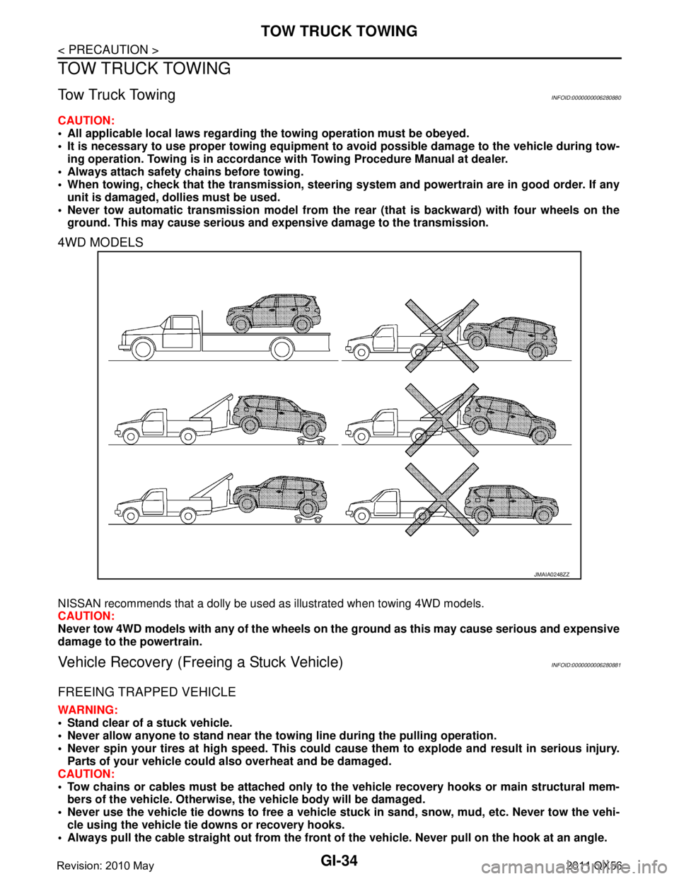
4WD MODELS
NISSAN recommends that a dolly be used as illustrated when towing 4WD models.
CAUTION:
Never tow 4WD models with any of the wheels on the ground as this may cause serious and expensive
damage to the powertrain.
Vehicle Recovery (Freeing a Stuck Vehicle)INFOID:0000000006280881
FREEING TRAPPED VEHICLE
WARNING:
Stand clear of a stuck vehicle.
Never allow anyone to stand near the towing line during the pulling operation.
Never spin your tires at high sp eed. This could cause them to explode and result in serious injury.
Parts of your vehicle could also overheat and be damaged.
CAUTION:
Tow chains or cables must be attached only to the vehicle recovery hooks or main structural mem-
bers of the vehicle. Otherwise, the vehicle body will be damaged.
Never use the vehicle tie downs to free a vehicle st uck in sand, snow, mud, etc. Never tow the vehi-
cle using the vehicle tie downs or recovery hooks.
Always pull the cable straight out from the front of the vehicle. Never pull on the hook at an angle.
JMAIA0248ZZ
Revision: 2010 May2011 QX56
Page 2999 of 5598
TOW TRUCK TOWINGGI-35
< PRECAUTION >
C
DE
F
G H
I
J
K L
M B
GI
N
O P
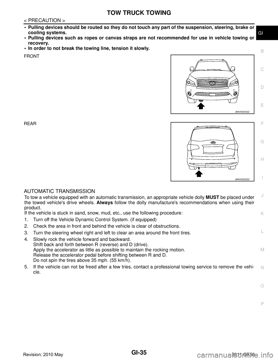
Pulling devices should be routed so they do not touch any part of the suspension, steering, brake or
cooling systems.
Pulling devices such as ropes or canvas straps ar e not recommended for use in vehicle towing or
recovery.
In order to not break the towi ng line, tension it slowly.
FRONT
REAR
AUTOMATIC TRANSMISSION
To tow a vehicle equipped with an automatic tr ansmission, an appropriate vehicle dolly MUST be placed under
the towed vehicle's drive wheels. Always follow the dolly manufacture's recommendations when using their
product.
If the vehicle is stuck in sand, snow , mud, etc., use the following procedure:
1. Turn off the Vehicle Dynam ic Control System. (if equipped)
2. Check the area in front and behind the vehicle is clear of obstructions.
3. Turn the steering wheel right and left to clear an area around the front tires.
4. Slowly rock the vehicle forward and backward. Shift back and forth between R (reverse) and D (drive).
Apply the accelerator as little as possible to maintain the rocking motion.
Release the accelerator pedal before shifting between R and D.
Do not spin the tires above 35 mph. (55 km/h).
5. If the vehicle can not be freed after a few tries, cont act a professional towing service to remove the vehi-
cle.
JMAIA0254ZZ
JMAIA0255ZZ
Revision: 2010 May2011 QX56
Page 3676 of 5598
MA-6
< PERIODIC MAINTENANCE >
PERIODIC MAINTENANCE
PERIODIC MAINTENANCE
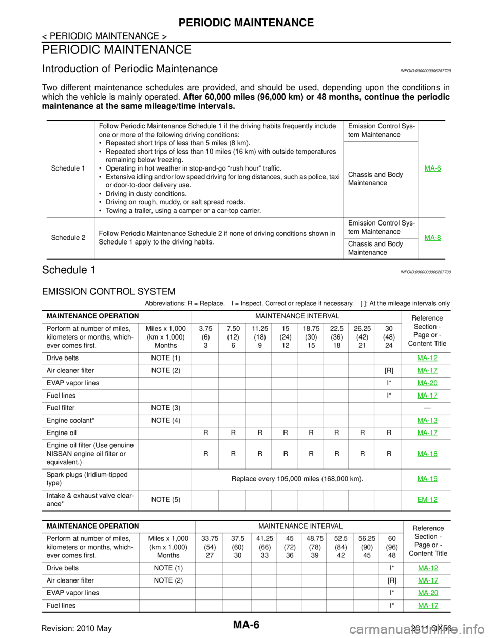
Introduction of Periodic MaintenanceINFOID:0000000006287729
Two different maintenance schedules are provided, and should be used, depending upon the conditions in
which the vehicle is mainly operated. After 60,000 miles (96,000 km) or 48 months, continue the periodic
maintenance at the same mileage/time intervals.
Schedule 1INFOID:0000000006287730
EMISSION CONTROL SYSTEM
Abbreviations: R = Replace. I = Inspec t. Correct or replace if necessary. [ ]: At the mileage intervals only
Schedule 1Follow Periodic Maintenance Schedule 1 if the driving habits frequently include
one or more of the following driving conditions:
Repeated short trips of less than 5 miles (8 km).
Repeated short trips of less than 10 miles (16 km) with outside temperatures
remaining below freezing.
Operating in hot weather in stop-and-go “rush hour” traffic.
Extensive idling and/or low speed driving for long distances, such as police, taxi
or door-to-door delivery use.
Driving in dusty conditions.
Driving on rough, muddy, or salt spread roads.
Towing a trailer, using a camper or a car-top carrier. Emission Control Sys-
tem Maintenance
MA-6Chassis and Body
Maintenance
Schedule 2 Follow Periodic Maintenance Schedule 2 if none of driving conditions shown in
Schedule 1 apply to the driving habits. Emission Control Sys-
tem Maintenance
MA-8
Chassis and Body
Maintenance
MAINTENANCE OPERATION MAINTENANCE INTERVAL
Reference
Section -
Page or -
Content Title
Perform at number of miles,
kilometers or months, which-
ever comes first. Miles x 1,000
(km x 1,000) Months 3.75
(6)3 7.50
(12) 6 11 . 2 5
(18) 9 15
(24) 12 18.75
(30)15 22.5
(36) 18 26.25
(42)21 30
(48) 24
Drive belts NOTE (1) MA-12
Air cleaner filter NOTE (2) [R]MA-17
EVAP vapor linesI*MA-20
Fuel lines I*MA-17
Fuel filter NOTE (3) —
Engine coolant* NOTE (4) MA-13
Engine oil R R R R R R R RMA-17
Engine oil filter (Use genuine
NISSAN engine oil filter or
equivalent.)R R RRRRR R
MA-18
Spark plugs (Iridium-tipped
type)Replace every 105,000 miles (168,000 km).
MA-19
Intake & exhaust valve clear-
ance*NOTE (5)
EM-12
MAINTENANCE OPERATIONMAINTENANCE INTERVAL
Reference
Section -
Page or -
Content Title
Perform at number of miles,
kilometers or months, which-
ever comes first. Miles x 1,000
(km x 1,000) Months 33.75
(54)27 37.5
(60) 30 41.25
(66)33 45
(72) 36 48.75
(78)39 52.5
(84) 42 56.25
(90)45 60
(96) 48
Drive belts NOTE (1) I* MA-12
Air cleaner filter NOTE (2) [R]MA-17
EVAP vapor linesI*MA-20
Fuel lines I*MA-17
Revision: 2010 May2011 QX56
Page 3678 of 5598
MA-8
< PERIODIC MAINTENANCE >
PERIODIC MAINTENANCE
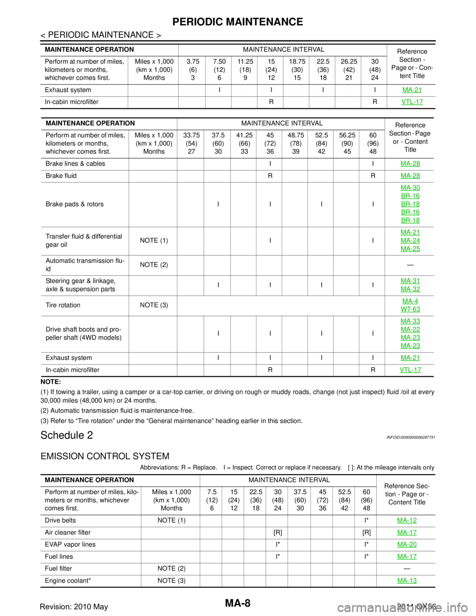
NOTE:
(1) If towing a trailer, using a camper or a car-top carrier, or driving on rough or muddy roads, change (not just inspect) fluid /oil at every
30,000 miles (48,000 km) or 24 months.
(2) Automatic transmission fluid is maintenance-free.
(3) Refer to “Tire rotation” unde r the “General maintenance” heading earlier in this section.
Schedule 2INFOID:0000000006287731
EMISSION CONTROL SYSTEM
Abbreviations: R = Replace. I = Inspec t. Correct or replace if necessary. [ ]: At the mileage intervals only
Exhaust system I I I I MA-21
In-cabin microfilter R RVTL-17
MAINTENANCE OPERATIONMAINTENANCE INTERVAL
Reference
Section -
Page or - Con- tent Title
Perform at number of miles,
kilometers or months,
whichever comes first. Miles x 1,000
(km x 1,000)
Months 3.75
(6)
3 7.50
(12)
6 11 . 2 5
(18)
9 15
(24)
12 18.75
(30)
15 22.5
(36)
18 26.25
(42)
21 30
(48)
24
MAINTENANCE OPERATION MAINTENANCE INTERVAL
Reference
Section - Page
or - Content Title
Perform at number of miles,
kilometers or months,
whichever comes first. Miles x 1,000
(km x 1,000) Months 33.75
(54)27 37.5
(60) 30 41.25
(66)33 45
(72) 36 48.75
(78)39 52.5
(84) 42 56.25
(90)45 60
(96) 48
Brake lines & cables I I MA-28
Brake fluid R RMA-28
Brake pads & rotors I I I IMA-30
BR-16
BR-18
BR-16
BR-18
Transfer fluid & differential
gear oil
NOTE (1) I I MA-21MA-24
MA-25
Automatic transmission flu-
id
NOTE (2)
—
Steering gear & linkage,
axle & suspension parts IIII
MA-31
MA-32
Tire rotation NOTE (3) MA-4WT-63
Drive shaft boots and pro-
peller shaft (4WD models)IIII MA-33MA-22
MA-23
MA-23
Exhaust system I I I I
MA-21
In-cabin microfilter R RVTL-17
MAINTENANCE OPERATIONMAINTENANCE INTERVAL
Reference Sec-
tion - Page or -
Content Title
Perform at number of miles, kilo-
meters or months, whichever
comes first. Miles x 1,000
(km x 1,000)
Months 7.5
(12)
6 15
(24)
12 22.5
(36)
18 30
(48)
24 37.5
(60)
30 45
(72)
36 52.5
(84)
42 60
(96)
48
Drive belts NOTE (1) I* MA-12
Air cleaner filter [R] [R]MA-17
EVAP vapor lines I* I*MA-20
Fuel lines I* I*MA-17
Fuel filter NOTE (2) —
Engine coolant* NOTE (3) MA-13
Revision: 2010 May2011 QX56