2011 INFINITI QX56 oil pump
[x] Cancel search: oil pumpPage 2317 of 5598

P0300, P0301, P0302, P0303, P0304, P0305, P0306, P0307, P0308 MISFIRE
EC-293
< DTC/CIRCUIT DIAGNOSIS > [VK56VD]
C
D
E
F
G H
I
J
K L
M A
EC
NP
O
Stop engine and visually check exhaust tube, three way catalyst and muffler for dents.
Is the inspection result normal?
YES-1 >> With CONSULT-III: GO TO 3.
YES-2 >> Without CONSULT-III: GO TO 4.
NO >> Repair or replace malfunctioning part.
3.PERFORM POWER BALANCE TEST
WITH CONSULT-III
1. Start engine.
2. Perform “POWER BALANCE” in “A CTIVE TEST” mode with CONSULT-III.
3. Check that each circuit produces a momentary engine speed drop.
Is the inspection result normal?
YES >> GO TO 9.
NO >> GO TO 4.
4.CHECK FUNCTION OF FUEL INJECTOR-I
1. Start engine and let it idle.
2. Listen to each fuel injector operation.
Is the inspection result normal?
YES >> GO TO 5.
NO >> Perform trouble diagnosis for FUEL INJECTOR, refer to EC-498, "
Diagnosis Procedure".
5.CHECK FUNCTION OF IGNITION COIL-I
CAUTION:
Perform the following procedure in a place with no combustible objects and good ventilation.
1. Turn ignition switch OFF.
2. Remove fuel pump fuse No. in IPDM E/R to release fuel pressure. NOTE:
Do not use CONSULT-III to release fuel pressure, or fuel pressure applies again during the following pro-
cedure.
3. Start engine.
4. After engine stalls, crank it 2 or 3 times to release all fuel pressure.
5. Turn ignition switch OFF.
6. Remove all ignition coil harness connectors to avoid the electrical discharge from the ignition coils.
7. Remove ignition coil and spark plug of the cylinder to be checked.
8. Crank engine for 5 seconds or more to remove combustion gas in the cylinder.
9. Connect spark plug and harness connector to ignition coil.
10. Fix ignition coil using a rope etc. with gap of 13 - 17 mm (0.52 - 0.66 in) between the edge of the spark plug and grounded metal
portion as shown in the figure.
11. Crank engine for approximately 3 seconds, and check whether spark is generated between the spark plug and the grounded
metal portion.
CAUTION:
Never place the spark plug and the ignition coil within 50
cm (19.7 in) each other. Be careful not to get an electrical
shock while checking, becau se the electrical discharge
voltage becomes 20 kV or more.
It might damage the ignition coil if the gap of more than 17 mm (0.66 in) is made.
NOTE:
Clicking sound should be heard.
PBIB3332E
Spark should be generated.
JMBIA0066GB
Revision: 2010 May2011 QX56
Page 2333 of 5598

P0420, P0430 THREE WAY CATALYST FUNCTIONEC-309
< DTC/CIRCUIT DIAGNOSIS > [VK56VD]
C
D
E
F
G H
I
J
K L
M A
EC
NP
O
Diagnosis ProcedureINFOID:0000000006217853
1.CHECK EXHAUST SYSTEM
Visually check exhaust tubes and muffler for dents.
Is the inspection result normal?
YES >> GO TO 2.
NO >> Repair or replace malfunctioning part.
2.CHECK EXHAUST GAS LEAKAGE
1. Start engine and run it at idle.
2. Listen for an exhaust gas leakage before the three way catalyst (manifold).
Is exhaust gas leakage detected?
YES >> Repair or replace malfunctioning part.
NO >> GO TO 3.
3.CHECK INTAKE AIR LEAKAGE
Listen for an intake air leakage after the mass air flow sensor.
Is intake air leakage detected?
YES >> Repair or replace malfunctioning part.
NO >> GO TO 4.
4.CHECK IDLE SPEED AND IGNITION TIMING
Check idle speed and ignition timing.
For procedure, refer to EC-530, "
Inspection" and EC-531, "Inspection".
For specification, refer to EC-538, "
Idle Speed" and EC-538, "Ignition Timing".
Is the inspection result normal?
YES >> GO TO 5.
NO >> Follow the EC-139, "
Work Procedure".
5.CHECK FUEL INJECTORS
Refer to EC-498, "
Component Function Check".
Is the inspection result normal?
YES >> GO TO 6.
NO >> Perform EC-498, "
Diagnosis Procedure".
6.CHECK FUNCTION OF IGNITION COIL-I
CAUTION:
Perform the following procedure in a place with no combustible objects and good ventilation.
1. Turn ignition switch OFF.
2. Remove fuel pump fuse in IPDM E/R to release fuel pressure.
NOTE:
For the fuse number, refer to EC-114, "
Wiring Diagram".
For the fuse arrangement, refer to PG-140, "
Fuse, Connector and Terminal Arrangement".
Do not use CONSULT-III to release fuel pressure, or fuel pressure applies again during the following
procedure.
3. Start engine.
4. After engine stalls, crank it 2 or 3 times to release all fuel pressure.
5. Turn ignition switch OFF.
PBIB1216E
Revision: 2010 May2011 QX56
Page 2424 of 5598

EC-400
< DTC/CIRCUIT DIAGNOSIS >[VK56VD]
P1217 ENGINE OVER TEMPERATURE
P1217 ENGINE OVER TEMPERATURE
DTC LogicINFOID:0000000006217909
DTC DETECTION LOGIC
NOTE:
If DTC P1217 is displayed with DTC UXXXX, perform the trouble diagnosis for DTC UXXXX.
If DTC P1217 is displayed with DTC P0607, perfo rm the trouble diagnosis for DTC P0607. Refer to
EC-378, "
DTC Logic".
If DTC P1217 is displayed with DTC P0527, perfo rm the trouble diagnosis for DTC P0527. Refer to
EC-367, "
DTC Logic".
If the cooling fan or any of other components in the cooling system has a malfunction, engine coolant temper-
ature increases.
When the engine coolant temperature reaches an abnorma lly high temperature condition, a malfunction is
indicated.
CAUTION:
When a malfunction is indicated, al ways replace the coolant. Refer to CO-8, "
Draining" and CO-9,
"Refilling". Also, replace the engine oil. Refer to LU-8, "Draining" and LU-8, "Refilling".
1. Fill radiator with coolant up to specified level with a filling speed of 2 liters per minute. Always use
coolant with the proper mixture ratio. Refer to MA-11, "
Anti-Freeze Coolant Mixture Ratio".
2. After refilling coolant, run engine to en sure that no water-flow noise is emitted.
DTC CONFIRMATION PROCEDURE
1.PERFORM COMPONENT FUNCTION CHECK
Perform component function check. Refer to EC-400, "
Component Function Check".
NOTE:
Use component function check to check the overall functi on of the cooling fan. During this check, a DTC might
not be confirmed.
Is the inspection result normal?
YES >> INSPECTION END
NO >> Go to EC-401, "
Diagnosis Procedure".
Component Function CheckINFOID:0000000006217910
1.PERFORM COMPONENT FUNCTION CHECK-I
WARNING:
Never remove the reservoir tank cap when the engi ne is hot. Serious burns could be caused by high
pressure fluid escaping from the radiator.
Wrap a thick cloth around cap. Carefully remove the cap by turning it a quarter turn to allow built-up
pressure to escape. Then turn the cap all the way off.
DTC No. Trouble diagnosis name DTC detecting condition Possible cause
P1217 Engine over temperature
(Overheat) Cooling fan does not operate properly
(Overheat).
Cooling fan system does not operate properly (Overheat).
Engine coolant is not within the specified quantity. Harness or connectors
(The cooling fan circuit is open or shorted.)
IPDM E/R
Electrically-controlled cooling fan coupling
Cooling fan speed sensor
Radiator hose
Radiator
Reservoir tank cap
Water pump
Thermostat
Revision: 2010 May2011 QX56
Page 2534 of 5598

EC-510
< DTC/CIRCUIT DIAGNOSIS >[VK56VD]
IGNITION SIGNAL
3. Remove fuel pump fuse in IPDM E/R to release fuel pressure.
NOTE:
For the fuse number, refer to EC-114, "
Wiring Diagram".
For the fuse arrangement, refer to PG-143, "
Fuse, Connector and Terminal Arrangement".
Do not use CONSULT-III to release fuel pressure , or fuel pressure applies again during the following
procedure.
4. Start engine.
5. After engine stalls, crank it 2 or 3 times to release all fuel pressure.
6. Turn ignition switch OFF.
7. Remove all ignition coil harness connectors to avoi d the electrical discharge from the ignition coils.
8. Remove ignition coil and spark plug of the cylinder to be checked.
9. Crank engine for 5 seconds or more to remove combustion gas in the cylinder.
10. Connect spark plug and harness connector to ignition coil.
11. Fix ignition coil using a rope etc. with gap of 13 - 17 mm (0.52 - 0.66 in) between the edge of the spark plug and grounded metal
portion as shown in the figure.
12. Crank engine for approximately 3 seconds, and check whether
spark is generated between the spark plug and the grounded
metal portion.
CAUTION:
Never place the spark plug and the ignition coil within 50
cm (19.7 in) each other. Be careful not to get an electrical
shock while checking, becau se the electrical discharge
voltage becomes 20 kV or more.
It might damage the ignition coil if the gap of more than 17 mm (0.66 in) is made.
NOTE:
When the gap is less than 13 mm (0.52 in), a spark might be generated even if the coil is malfunc-
tioning.
Is the inspection result normal?
YES >> INSPECTION END
NO >> Replace malfunctioning ignition coil with power transistor.
Component Inspection (Condenser)INFOID:0000000006218014
1.CHECK CONDENSER
1. Turn ignition switch OFF.
2. Disconnect condenser harness connector.
3. Check resistance between condenser terminals as per the following.
Is the inspection result normal?
YES >> INSPECTION END
NO >> Replace condenser. Spark should be generated.
JMBIA0066GB
Terminals Resistance
1 and 2 Above 1 M Ω [at 25 °C (77 °F)]
Revision: 2010 May2011 QX56
Page 2548 of 5598

EC-524
< SYMPTOM DIAGNOSIS >[VK56VD]
ENGINE CONTROL SYSTEM SYMPTOMS
SYMPTOM DIAGNOSIS
ENGINE CONTROL SYSTEM SYMPTOMS
Symptom TableINFOID:0000000006218028
SYSTEM — BASIC ENGINE CONTROL SYSTEM
SYMPTOM
Reference
page
HARD/NO START/RESTART (EXCP. HA)
ENGINE STALL
HESITATION/SURGING/FLAT SPOT
SPARK KNOCK/DETONATION
LACK OF POWER/POOR ACCELERATION
HIGH IDLE/LOW IDLE
ROUGH IDLE/HUNTING
IDLING VIBRATION
SLOW/NO RETURN TO IDLE
OVERHEATS/WATER TEMPERATURE HIGH
EXCESSIVE FUEL CONSUMPTION
EXCESSIVE OIL CONSUMPTION
BATTERY DEAD (UNDER CHARGE)
Warranty symptom code AA AB AC AD AE AF AG AH AJ AK AL AM HA
Fuel Low pressure fuel pump circuit 11232 22 3 2 EC-512
Low fuel pressure sensor circuit 4 4EC-483
Fuel pressure regulator system 334444444 4EC-198
Fuel injector circuit 11232 22 2EC-498
Evaporative emission system 334444444 4EC-532
FRP sensor circuit 11222 22 2EC-276EC-279
High pressure fuel pump circuit 4 3
EC-501
Air Positive crankcase ventilation sys-
tem 334444444 41
EC-534
Incorrect idle speed adjustment 1 1 1 1 1 EC-139
Electric throttle control actuator 112332222 2 2EC-460EC-466
IgnitionIncorrect ignition timing adjustment33111 11 1
EC-139
Ignition circuit 11222 22 2EC-506
Main power supply and ground circuit 22333 33 23 EC-168
Revision: 2010 May2011 QX56
Page 2552 of 5598

E C -528
< SYMPTOM DIAGNOSIS >[VK56VD]
ENGINE CONTROL SYSTEM SYMPTOMS
1 - 6: The numbers refer to the order of inspection.Lubrica-
tion
Oil pan/Oil strainer/Oil pump/Oil
filter/Oil gallery/Oil cooler 55555 55 5 EM-56
EM-60
LU-9
LU-12
LU-14
Oil level (Low)/Filthy oil
LU-7
Cooling
Radiator/Hose/Radiator filler cap
55555 55 45 CO-11
CO-11
Thermostat 5
CO-21
Water pumpCO-19
Water galleryEM-115
Cooling fan
5CO-17
Coolant level (Low)/Contaminat-
ed coolant
CO-8
IVIS (INFINITI Vehicle Immobilizer System —
NATS)11
SEC-48
SYMPTOM
Reference
page
HARD/NO START/RESTART (EXCP. HA)
ENGINE STALL
HESITATION/SURGING/FLAT SPOT
SPARK KNOCK/DETONATION
LACK OF POWER/POOR ACCELERATION
HIGH IDLE/LOW IDLE
ROUGH IDLE/HUNTING
IDLING VIBRATION
SLOW/NO RETURN TO IDLE
OVERHEATS/WATER TEMPERATURE HIGH
EXCESSIVE FUEL CONSUMPTION
EXCESSIVE OIL CONSUMPTION
BATTERY DEAD (UNDER CHARGE)
Warranty symptom code AA AB AC AD AE AF AG AH AJ AK AL AM HA
Revision: 2010 May2011 QX56
Page 2564 of 5598
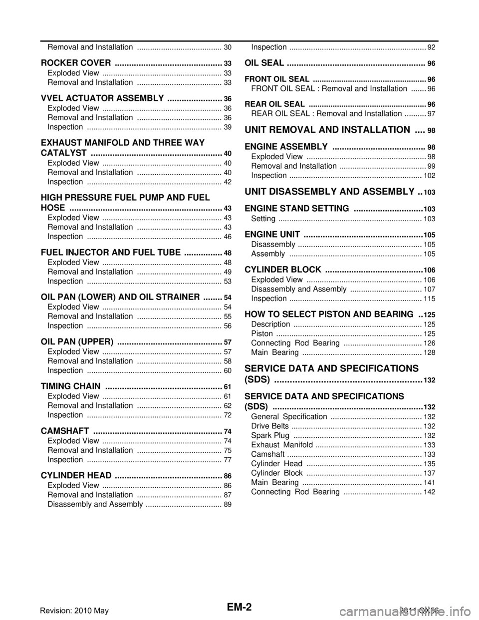
EM-2
Removal and Installation ........................................30
ROCKER COVER ..............................................33
Exploded View ..................................................... ...33
Removal and Installation ........................................33
VVEL ACTUATOR ASSEMBLY ........................36
Exploded View ..................................................... ...36
Removal and Installation ........................................36
Inspection ...............................................................39
EXHAUST MANIFOLD AND THREE WAY
CATALYST ........................................................
40
Exploded View ..................................................... ...40
Removal and Installation ........................................40
Inspection ...............................................................42
HIGH PRESSURE FUEL PUMP AND FUEL
HOSE .................................................................
43
Exploded View ..................................................... ...43
Removal and Installation ........................................43
Inspection ...............................................................46
FUEL INJECTOR AND FUEL TUBE .................48
Exploded View ..................................................... ...48
Removal and Installation ........................................49
Inspection ...............................................................53
OIL PAN (LOWER) AND OIL STRAINER .........54
Exploded View ..................................................... ...54
Removal and Installation ........................................55
Inspection ...............................................................56
OIL PAN (UPPER) .......................................... ...57
Exploded View ..................................................... ...57
Removal and Installation ........................................58
Inspection ...............................................................60
TIMING CHAIN ............................................... ...61
Exploded View ..................................................... ...61
Removal and Installation ........................................62
Inspection ...............................................................72
CAMSHAFT .......................................................74
Exploded View ..................................................... ...74
Removal and Installation ........................................75
Inspection ...............................................................77
CYLINDER HEAD ..............................................86
Exploded View ..................................................... ...86
Removal and Installation ........................................87
Disassembly and Assembly ....................................89
Inspection ............................................................. ...92
OIL SEAL ...........................................................96
FRONT OIL SEAL .................................................. ...96
FRONT OIL SEAL : Removal and Installation ........96
REAR OIL SEAL .................................................... ...96
REAR OIL SEAL : Removal and Installation ...........97
UNIT REMOVAL AND INSTALLATION ....98
ENGINE ASSEMBL Y ..................................... ...98
Exploded View ..................................................... ...98
Removal and Installation .........................................99
Inspection ..............................................................102
UNIT DISASSEMBLY AND ASSEMBLY ..103
ENGINE STAND SETTING ..............................103
Setting .................................................................. .103
ENGINE UNIT ...................................................105
Disassembly ......................................................... .105
Assembly ..............................................................105
CYLINDER BLOCK ..........................................106
Exploded View ..................................................... .106
Disassembly and Assembly ..................................107
Inspection ..............................................................115
HOW TO SELECT PISTON AND BEARING ...125
Description ........................................................... .125
Piston ....................................................................125
Connecting Rod Bearing .....................................126
Main Bearing ........................................................128
SERVICE DATA AND SPECIFICATIONS
(SDS) ........ .................................................
132
SERVICE DATA AND SPECIFICATIONS
(SDS) .............................................................. ..
132
General Specification .......................................... .132
Drive Belts .............................................................132
Spark Plug ............................................................132
Exhaust Manifold ..................................................133
Camshaft ...............................................................133
Cylinder Head ......................................................135
Cylinder Block ......................................................137
Main Bearing ........................................................141
Connecting Rod Bearing .....................................142
Revision: 2010 May2011 QX56
Page 2566 of 5598
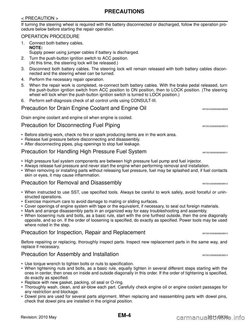
EM-4
< PRECAUTION >
PRECAUTIONS
If turning the steering wheel is required with the battery disconnected or discharged, follow the operation pro-
cedure below before starting the repair operation.
OPERATION PROCEDURE
1. Connect both battery cables.
NOTE:
Supply power using jumper cables if battery is discharged.
2. Turn the push-button ignition switch to ACC position. (At this time, the steering lock will be released.)
3. Disconnect both battery cables. The steering lock wi ll remain released with both battery cables discon-
nected and the steering wheel can be turned.
4. Perform the necessary repair operation.
5. When the repair work is completed, re-connect bot h battery cables. With the brake pedal released, turn
the push-button ignition switch from ACC position to ON position, then to LOCK position. (The steering
wheel will lock when the push-button igniti on switch is turned to LOCK position.)
6. Perform self-diagnosis check of all control units using CONSULT-III.
Precaution for Drain Engine Coolant and Engine OilINFOID:0000000006289509
Drain engine coolant and engine oil when engine is cooled.
Precaution for Disconnecting Fuel PipingINFOID:0000000006289510
Before starting work, check no fire or sp ark producing items are in the work area.
Release fuel pressure before disconnecting and disassembly.
After disconnecting pipes, plug openings to stop fuel leakage.
Precaution for Handling High Pressure Fuel SystemINFOID:0000000006289511
High pressure fuel system components are betw een high pressure fuel pump and fuel injector.
Always release fuel pressure and never start the engine when performing removal and installation.
When removing or installing parts without releasing fuel pressure, fuel may be splashed and, if fuel contacts
skin or eyes, it may cause inflammation.
Precaution for Removal and DisassemblyINFOID:0000000006289512
When instructed to use SST, use specified tools. Always be careful to work safely, avoid forceful or unin-
structed operations.
Exercise maximum care to avoid damage to mating or sliding surfaces.
Cover openings of engine system with tape or the equival ent, if necessary, to seal out foreign materials.
Mark and arrange disassembly parts in an organi zed way for easy troubleshooting and assembly.
When loosening nuts and bolts, as a basic rule, star t with the one furthest outside, then the one diagonally
opposite, and so on. If the order of loosening is specified, do exactly as specified. Power tools may be used
where noted in the step.
Precaution for Inspection, Repair and ReplacementINFOID:0000000006289513
Before repairing or replacing, thoroughly inspect parts. Inspect new replacement parts in the same way, and
replace if necessary.
Precaution for Assembly and InstallationINFOID:0000000006289514
Use torque wrench to tighten bolts or nuts to specification.
When tightening nuts and bolts, as a basic rule, equally tighten in several different steps starting with the
ones in center, then ones on inside and outside diagonally in this order. If the order of tightening is specified,
do exactly as specified.
Replace with new gasket, packing, oil seal or O-ring.
Thoroughly wash, clean, and air-blow each part. Carefully check engine oil or engine coolant passages for
any restriction and blockage.
Dowel pins are used for several parts alignment. When replacing and reassembling parts with dowel pins,
check that dowel pins are installed in the original position.
Revision: 2010 May2011 QX56