Page 169 of 419

491
Features of your vehicle
❈❈
2nd row outlet vents (E)
• The air flow of the 2nd row outlet vents is controlled by the front climate control
system and delivered through the
inside air duct of the front doors. If the
door is open or not closed completely,
the air flow of the 2nd row outlet vent is
not delivered properly. Make sure the
front doors are closed completely.
The air flow of the 2nd row outlet vents may be weaker than the instrument
panel vents for the long air duct in the
front doors.
Close the air vents in cold weather. The air flow of the 2nd row outlet vents may
cool a little during heating operation.
(Use the 2nd row outlet vents during
cooling operation.) D230101AEN
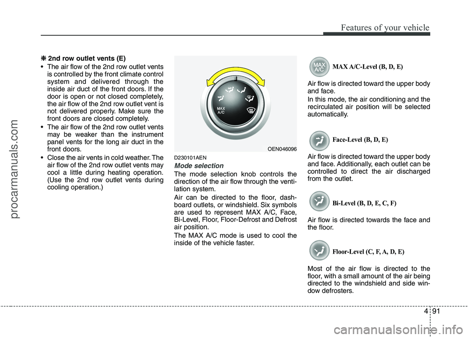
Mode selection
The mode selection knob controls the
direction of the air flow through the venti-lation system.
Air can be directed to the floor, dash-
board outlets, or windshield. Six symbols
are used to represent MAX A/C, Face,
Bi-Level, Floor, Floor-Defrost and Defrostair position. The MAX A/C mode is used to cool the
inside of the vehicle faster.
MAX A/C-Level (B, D, E)
Air flow is directed toward the upper body
and face.
In this mode, the air conditioning and the recirculated air position will be selected
automatically.
Face-Level (B, D, E)
Air flow is directed toward the upper body
and face. Additionally, each outlet can becontrolled to direct the air dischargedfrom the outlet.
Bi-Level (B, D, E, C, F)
Air flow is directed towards the face and
the floor.
Floor-Level (C, F, A, D, E)
Most of the air flow is directed to the
floor, with a small amount of the air beingdirected to the windshield and side win-
dow defrosters.
OEN046096
procarmanuals.com
Page 170 of 419

Features of your vehicle
92
4
Floor/Defrost-Level (A, C, F, D, E)
Most of the air flow is directed to the floor and the windshield with a small amount
directed to the side window defrosters.
Defrost-Level (A, D, E)
Most of the air flow is directed to thewindshield with a small amount of air
directed to the side window defrosters.
Instrument panel vents
The outlet vents can be opened or closed
separately using the horizontal thumb-
wheel. To close the vent, rotate it left to
the maximum position. To open the vent,
rotate it right to the desired position.
Also, you can adjust the direction of air
delivery from these vents using the vent
control lever as shown.D230102AUN
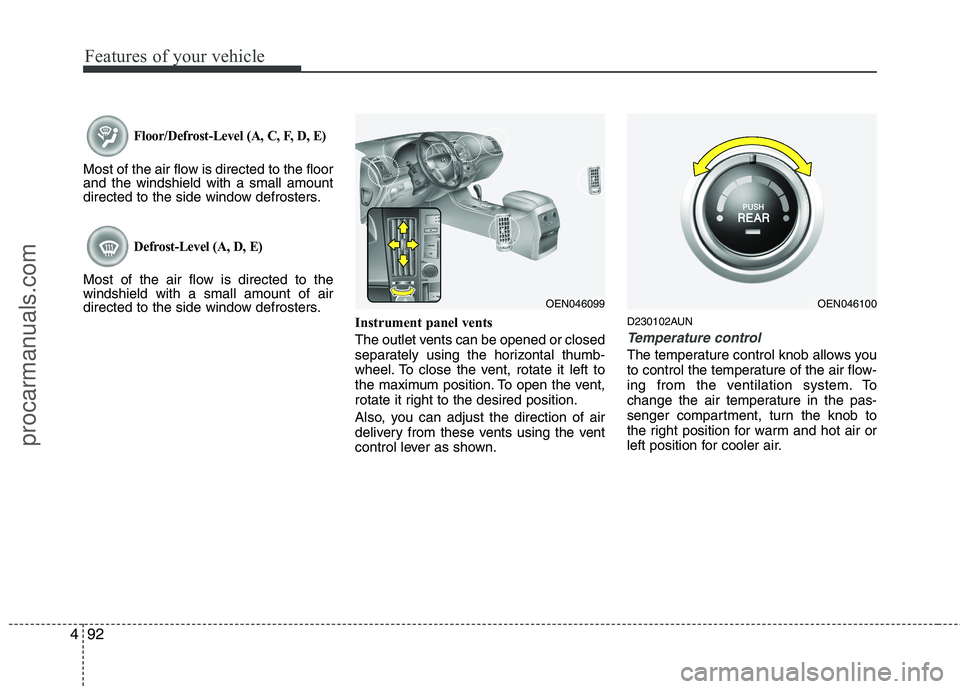
Temperature control
The temperature control knob allows you
to control the temperature of the air flow-
ing from the ventilation system. To
change the air temperature in the pas-
senger compartment, turn the knob to
the right position for warm and hot air or
left position for cooler air.
OEN046100OEN046099
procarmanuals.com
Page 180 of 419

Features of your vehicle
102
4
D240100CEN
Automatic heating and air condi- tioning The automatic climate control system is
controlled by simply setting the desired
temperature.
The Full Automatic Temperature Control
(FATC) system automatically controls the
heating and cooling system as follows;
1. Push the AUTO button. The modes,
fan speeds, air intake and air-condi- tioning will be controlled automatically
by temperature setting. 2. Push the TEMP button to set the
desired temperature.
If the temperature is set to the lowestsetting (Lo), the air conditioning sys-
tem will operate continuously.
3. To turn the automatic operation off, press any button or turn any knob
except the temperature control button.
If you press the mode selection button,
air conditioning button, defrost button
or air intake control button, or turn the
fan speed knob, the selected function
will be controlled manually while other
functions operate automatically.
For your convenience and to improve the
effectiveness of the climate control, use
the AUTO button and set the temperatureto 22°C/71°F (23°C/73°F - ExceptEurope).
✽✽ NOTICE
Never place anything over the sensor
located on the instrument panel to
ensure better control of the heating and
cooling system.
OEN046121OEN046120
procarmanuals.com
Page 182 of 419
Features of your vehicle
104
4
Defrost-Level (A, D, E)
Most of the air flow is directed to the windshield with a small amount of air
directed to the side window defrosters. Instrument panel vents
The outlet vents can be opened or closed
separately using the horizontal thumb-
wheel. To close the vent, rotate it left to
the maximum position. To open the vent,
rotate it right to the desired position.
Also, you can adjust the direction of air
delivery from these vents using the vent
control lever as shown.D240202AEN
Temperature control
The temperature will increase to the
maximum (HI) by pushing the up ( )
button.
The temperature will decrease to the min-
imum (Lo) by pushing the down ( ) but-ton.
When pushing the button, the tempera-
ture will increase or decrease by
0.5°C/1°F. When set to the lowest tem-
perature setting, the air conditioning will
operate continuously.
OEN046123OEN046099OEN046124
procarmanuals.com
Page 286 of 419

549
Driving your vehicle
E140401AUN
Following distance
Stay at least twice as far behind the vehi-
cle ahead as you would when driving
your vehicle without a trailer. This can
help you avoid situations that require
heavy braking and sudden turns.
E140402AUN
Passing
You’ll need more passing distance up
ahead when you’re towing a trailer. And,
because of the increased vehicle length,
you’ll need to go much farther beyond the
passed vehicle before you can return to
your lane.
E140403AUN
Backing up
Hold the bottom of the steering wheel
with one hand. Then, to move the trailer
to the left, just move your hand to the left.
To move the trailer to the right, move your
hand to the right. Always back up slowly
and, if possible, have someone guide
you.E140404AUN
Making turns
When you’re turning with a trailer, make
wider turns than normal. Do this so your
trailer won’t strike soft shoulders, curbs,
road signs, trees, or other objects. Avoid
jerky or sudden maneuvers. Signal well
in advance. E140405AFD
Turn signals when towing a trailer
When you tow a trailer, your vehicle has
to have a different turn signal flasher and
extra wiring. The green arrows on your
instrument panel will flash whenever you
signal a turn or lane change. Properly
connected, the trailer lights will also flash
to alert other drivers you’re about to turn,
change lanes, or stop.
When towing a trailer, the green arrows
on your instrument panel will flash for
turns even if the bulbs on the trailer are
burned out. Thus, you may think drivers
behind you are seeing your signals
when, in fact, they are not. It’s important
to check occasionally to be sure the trail-
er bulbs are still working. You must also
check the lights every time you discon-
nect and then reconnect the wires.Do not connect a trailer lighting system
directly to your vehicle’s lighting system.
Use only an approved trailer wiring har-
ness.
An authorized HYUNDAI dealer can
assist you in installing the wiring harness.
WARNING
Failure to use an approved trailer wiring harness could result in dam-
age to the vehicle electrical system
and/or personal injury.
procarmanuals.com
Page 375 of 419
Maintenance
58
7
G210100AEN Instrument panel fuse replace- ment
1. Turn the ignition switch and all other
switches off.
2. Open the fuse panel cover. 3. Pull the suspected fuse straight out.
Use the removal tool provided in the
fuse panel cover.
4. Check the removed fuse; replace it if it is blown.
Spare fuses are provided in the instru-
ment panel fuse panel (or in the enginecompartment fuse panel).
5. Push in a new fuse of the same rating, and make sure it fits tightly in the clips.
If it fits loosely, consult an authorized
HYUNDAI dealer.
If you do not have a spare, use a fuse of the same rating from a circuit you maynot need for operating the vehicle, suchas the cigarette lighter fuse.
If the headlights or other electrical com-
ponents do not work and the fuses are
OK, check the fuse panel in the engine
compartment. If a fuse is blown, it mustbe replaced.
OEN076022OEN076021
procarmanuals.com
Page 378 of 419
761
Maintenance
✽✽NOTICE
Not all fuse panel descriptions in this
manual may be applicable to your vehi-
cle. It is accurate at the time of printing.
When you inspect the fuse panel in your
vehicle, refer to the fuse panel label.Instrument panel fuse panel Engine compartment fuse panel
OEN076027/OEN076028/OEN076029
G210300BEN-EE
Fuse/relay panel description
Inside the fuse/relay panel covers, you can find the fuse/relay label describing fuse/relay name and capacity.
procarmanuals.com
Page 379 of 419

Maintenance
62
7
Instrument panel fuse panel
Description Fuse rating Protected component
AUDIO 2 10A Audio, Console & rear power outlet relay, Digital clock, BCM
C/LIGHTER 20A Front cigarette lighter & Power outlet
A/BAG 2 10A -
A/BAG 1 15A SRS control module
A/BAG IND 10A Instrument cluster (Air bag indicator lamp)
B/UP LP 10A Back-up lamp relay, TCM, Electro chromic mirror, Back warning control module
CRUISE 10A Multifunction switch, PIC immobilizer module, Driver/Passenger seat warmer switch
ATM CONT 10A ATM key lock unit, 4WD ECM, BCM, Multifunction switch, Semi active engine mounting control module
CLUSTER 10A Instrument cluster, Generator, BCM, PIC immobilizer module
START 10A Burglar alarm relay, Power tailgate control module
EPS 10A BCM, Rheostat, Power window main/assist switch
A/CON 10A Front A/C control module, Blower relay, Rear A/C control module, Rear A/C relay, Rain sensor, Sunroof control module, Electro chromic mirror
FR S/HTR 15A Driver/Passenger Seat warmer switch
RR S/HTR 15A -
IMS 10A IMS control module, Tilt & Telescopic module, PTC heater relay, Power tailgate control module
H/LP, AQS 10A Head lamp low relay, AQS sensor
FR WASHER 15A Front wiper relay, Front washer relay
RR WIPER 15A Rear wiper control module, Rear wiper motor
TAIL LH 10A Head lamp LH, Rear combi lamp LH, Front fog lamp relay, Tailgate handler license lamp
TAIL RH 10A Head lamp RH, Rear combi lamp RH, Glove box lamp, Illuminations
procarmanuals.com