Page 333 of 382
747
Maintenance
Cold Tire Pressure: The amount of
air pressure in a tire, measured in pounds per square inch (psi) or kilo-
pascals (kPa) before a tire has built
up heat from driving.
Curb Weight : This means the weight
of a motor vehicle with standard and optional equipment including the
maximum capacity of fuel, oil and
coolant, but without passengers and
cargo.
DOT Markings : A code molded into
the sidewall of a tire signifying that
the tire is in compliance with the U.S.
Department of Transportation motor
vehicle safety standards. The DOT
code includes the Tire Identification
Number (TIN), an alphanumeric des-ignator which can also identify the
tire manufacturer, production plant,
brand and date of production. GVWR : Gross Vehicle Weight Rating
GAWR FRT : Gross Axle Weight
Rating for the Front Axle.
GAWR RR : Gross Axle Weight
Rating for the Rear axle. Intended Outboard Sidewall
: The
side of an asymmetrical tire, that
must always face outward when
mounted on a vehicle.
Kilopascal (kPa) : The metric unit for
air pressure.
Load Index : An assigned number
ranging from 1 to 279 that corre-
sponds to the load carrying capacity
of a tire.
Maximum Inflation Pressure : The
maximum air pressure to which a
cold tire may be inflated. The maxi-
mum air pressure is molded onto the
sidewall.
Maximum Load Rating : The load
rating for a tire at the maximum per-
missible inflation pressure for that
tire.
Maximum Loaded Vehicle Weight :
The sum of curb weight; accessory
weight; vehicle capacity weight; and
production options weight.
Normal Occupant Weight :The
number of occupants a vehicle is
designed to seat multiplied by 150pounds (68 kg). Occupant Distribution
: Designated
seating positions.
Outward Facing Sidewall: The side
of a asymmetrical tire that has a par-
ticular side that faces outward when
mounted on a vehicle. The outward
facing sidewall bears white lettering
or bears manufacturer, brand, and/ormodel name molding that is higher ordeeper than the same moldings on
the inner facing sidewall.
Passenger (P-Metric) Tire : A tire
used on passenger cars and some
light duty trucks and multipurpose
vehicles. Recommended Inflation Pressure :
Vehicle manufacturer's recommend-
ed tire inflation pressure and shownon the tire placard.
Radial Ply Tire : A pneumatic tire in
which the ply cords that extend to the
beads are laid at 90 degrees to the
centerline of the tread. Rim : A metal support for a tire and
upon which the tire beads are seat- ed.
Sidewall : The portion of a tire
between the tread and the bead.
Page 336 of 382
Maintenance
50
7
FUSES
A vehicle’s electrical system is protected
from electrical overload damage by
fuses.
This vehicle has 3 fuse panels, one locat-
ed in the driver’s side panel bolster, the
other in the engine compartment.
If any of your vehicle’s lights, acces-
sories, or controls do not work, check the
appropriate circuit fuse. If a fuse has
blown, the element inside the fuse willmelt.
If the electrical system does not work,
first check the driver’s side fuse panel.
Always replace a blown fuse with one of
the same rating.
If the replacement fuse blows, this indi-
cates an electrical problem. Avoid using
the system involved and immediately
consult an authorized HYUNDAI dealer.
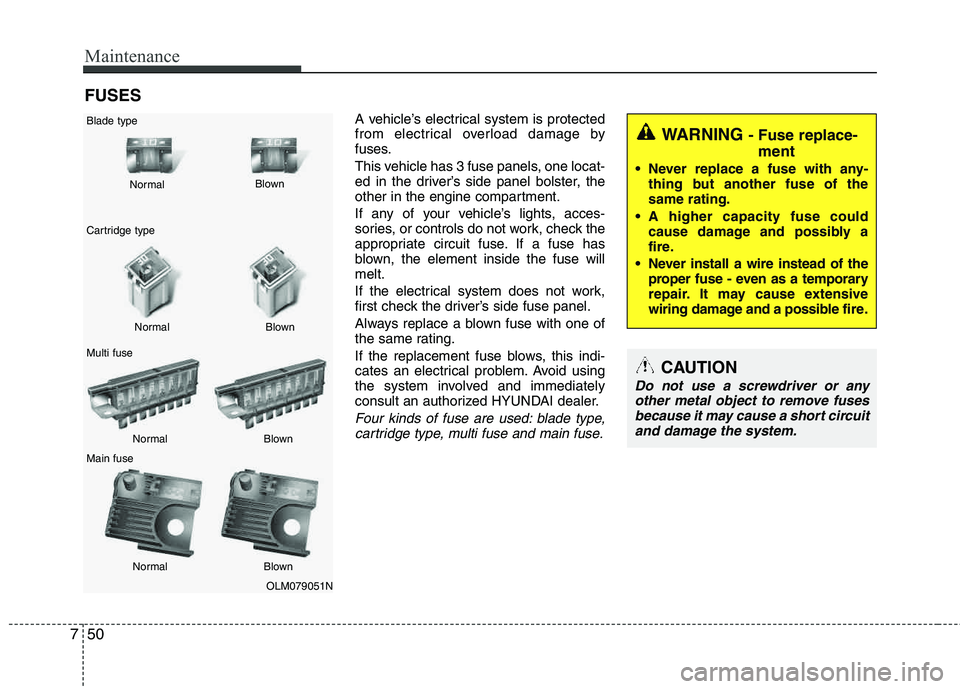
Four kinds of fuse are used: blade type,cartridge type, multi fuse and main fuse.
WARNING - Fuse replace-
ment
Never replace a fuse with any- thing but another fuse of the same rating.
A higher capacity fuse could cause damage and possibly a
fire.
Never install a wire instead of the proper fuse - even as a temporary
repair. It may cause extensive
wiring damage and a possible fire.
CAUTION
Do not use a screwdriver or any
other metal object to remove fuses
because it may cause a short circuitand damage the system.
OLM079051N
Normal
Normal
Blade type
Cartridge type Multi fuse Main fuse Blown
Blown
Normal Blown
Normal Blown
Page 337 of 382
751
Maintenance
Instrument panel fuse replace- ment
1. Turn the ignition switch and all otherswitches off.
2. Open the fuse panel cover. 3. Pull the suspected fuse straight out.
Use the removal tool provided in the fuse panel.
4. Check the removed fuse; replace it if it is blown.
Spare fuses are provided in the instru-
ment panel fuse panel (or in the enginecompartment fuse panel).
5. Push in a new fuse of the same rating, and make sure it fits tightly in the clips.
If it fits loosely, consult an authorized
HYUNDAI dealer.
If you do not have a spare, use a fuse of the same rating from a circuit you maynot need for operating the vehicle, such as the cigarette lighter fuse.
If the headlights or other electrical com-
ponents do not work and the fuses are
OK, check the fuse panel in the engine
compartment. If a fuse is blown, it mustbe replaced.
OLM079020OLM079021N
Page 338 of 382
Maintenance
52
7
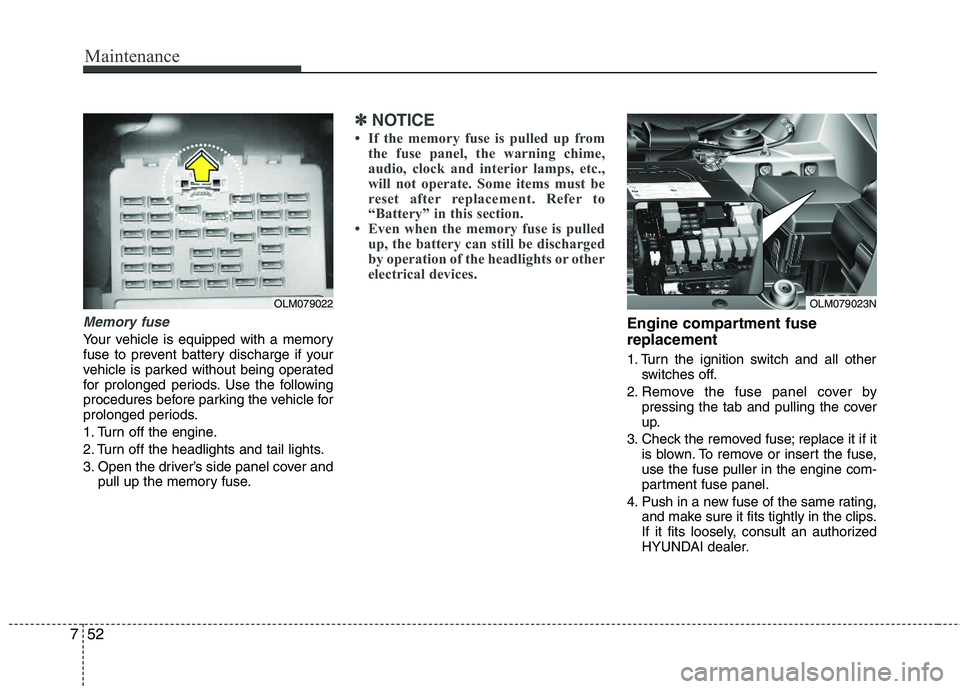
Memory fuse
Your vehicle is equipped with a memory
fuse to prevent battery discharge if your
vehicle is parked without being operated
for prolonged periods. Use the following
procedures before parking the vehicle for
prolonged periods.
1. Turn off the engine.
2. Turn off the headlights and tail lights.
3. Open the driver’s side panel cover and
pull up the memory fuse.
✽✽ NOTICE
If the memory fuse is pulled up from the fuse panel, the warning chime,
audio, clock and interior lamps, etc.,
will not operate. Some items must be
reset after replacement. Refer to
“Battery” in this section.
Even when the memory fuse is pulled
up, the battery can still be discharged
by operation of the headlights or other
electrical devices.
Engine compartment fuse replacement
1. Turn the ignition switch and all other switches off.
2. Remove the fuse panel cover by pressing the tab and pulling the cover
up.
3. Check the removed fuse; replace it if it is blown. To remove or insert the fuse,use the fuse puller in the engine com-
partment fuse panel.
4. Push in a new fuse of the same rating, and make sure it fits tightly in the clips.
If it fits loosely, consult an authorized
HYUNDAI dealer.
OLM079023NOLM079022
Page 341 of 382
755
Maintenance
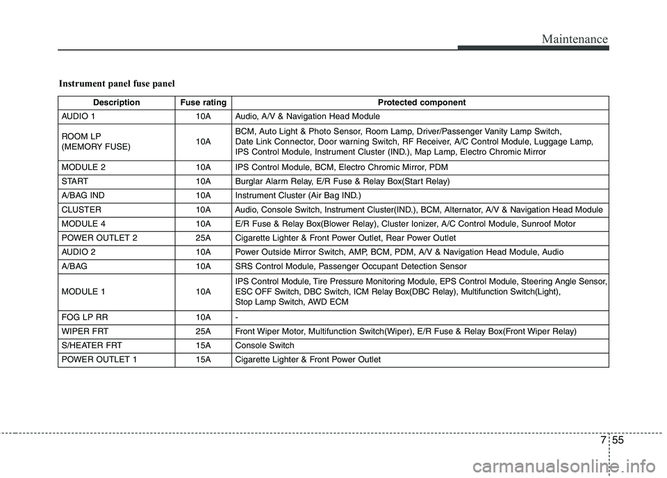
Instrument panel fuse panel
Description Fuse ratingProtected component
AUDIO 1 10A Audio, A/V & Navigation Head Module
ROOM LP
(MEMORY FUSE) 10ABCM, Auto Light & Photo Sensor, Room Lamp, Driver/Passenger Vanity Lamp Switch,
Date Link Connector, Door warning Switch, RF Receiver, A/C Control Module, Luggage Lamp,
IPS Control Module, Instrument Cluster (IND.), Map Lamp, Electro Chromic Mirror
MODULE 2 10A IPS Control Module, BCM, Electro Chromic Mirror, PDM
START 10A Burglar Alarm Relay, E/R Fuse & Relay Box(Start Relay)
A/BAG IND 10A Instrument Cluster (Air Bag IND.)
CLUSTER 10A Audio, Console Switch, Instrument Cluster(IND.), BCM, Alternator, A/V & Navigation Head Module
MODULE 4 10A E/R Fuse & Relay Box(Blower Relay), Cluster Ionizer, A/C Control Module, Sunroof Motor
POWER OUTLET 2 25A Cigarette Lighter & Front Power Outlet, Rear Power Outlet
AUDIO 2 10A Power Outside Mirror Switch, AMP, BCM, PDM, A/V & Navigation Head Module, Audio
A/BAG 10A SRS Control Module, Passenger Occupant Detection Sensor
MODULE 1 10A IPS
Control Module, Tire Pressure Monitoring Module, EPS ControlModule, Steering Angle Sensor,
ESC OFF Switch, DBC Switch, ICM Relay Box(DBC Relay), Multifunction Switch(Light),
Stop Lamp Switch, AWD ECM
FOG LP RR 10A -
WIPER FRT 25A Front Wiper Motor, Multifunction Switch(Wiper), E/R Fuse & Relay Box(Front Wiper Relay)
S/HEATER FRT 15A Console Switch
POWER OUTLET 1 15A Cigarette Lighter & Front Power Outlet
Page 345 of 382
759
Maintenance
LIGHT BULBS
Use only the bulbs of the specifiedwattage.
✽✽ NOTICE
After heavy, driving rain or washing,
headlight and taillight lenses could
appear frosty. This condition is caused by
the temperature difference between the
lamp inside and outside. This is similar
to the condensation on your windows
inside your vehicle during the rain and
doesn’t indicate a problem with your
vehicle. If the water leaks into the lamp
bulb circuitry, have the vehicle checked
by an authorized HYUNDAI dealer.
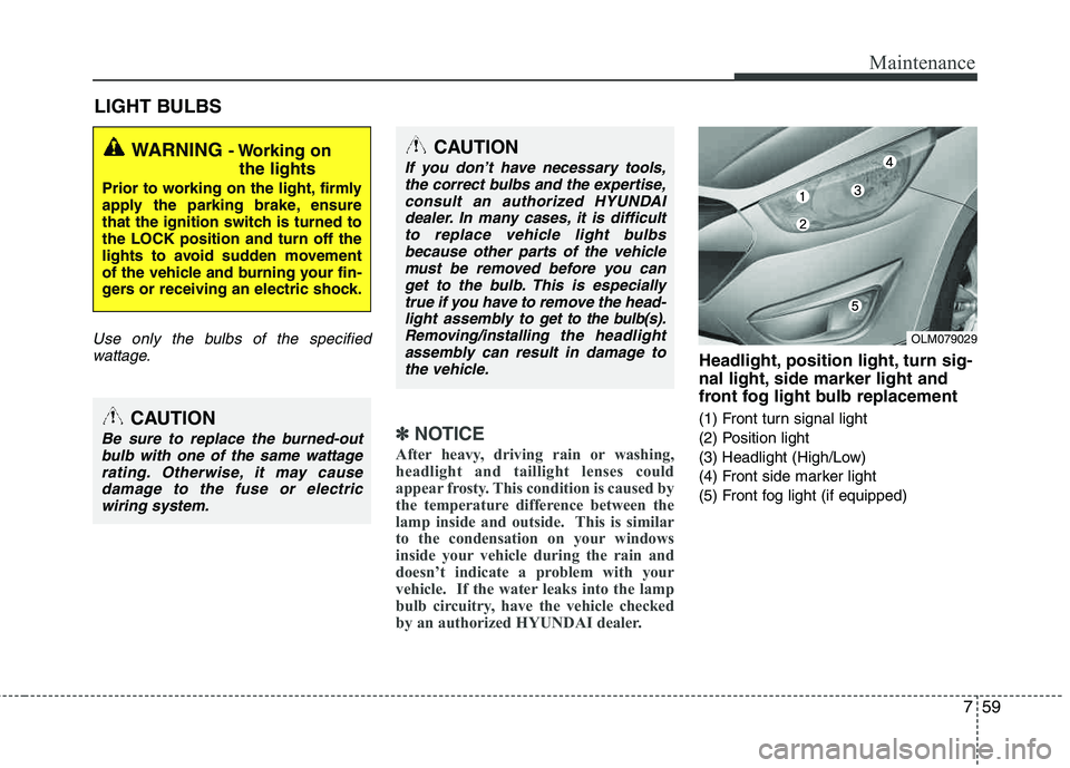
Headlight, position light, turn sig-
nal light, side marker light and
front fog light bulb replacement
(1) Front turn signal light
(2) Position light
(3) Headlight (High/Low)
(4) Front side marker light
(5) Front fog light (if equipped)
WARNING - Working on the lights
Prior to working on the light, firmly
apply the parking brake, ensure
that the ignition switch is turned tothe LOCK position and turn off the
lights to avoid sudden movement
of the vehicle and burning your fin-
gers or receiving an electric shock.
CAUTION
Be sure to replace the burned-outbulb with one of the same wattagerating. Otherwise, it may cause damage to the fuse or electric
wiring system.
CAUTION
If you don’t have necessary tools, the correct bulbs and the expertise,consult an authorized HYUNDAI
dealer. In many cases, it is difficultto replace vehicle light bulbsbecause other parts of the vehiclemust be removed before you can
get to the bulb. This is especiallytrue if you have to remove the head-light assembly to
get to the bulb(s).
Removing/installingthe headlight
assembly can result in damage to
the vehicle.OLM079029
Page 346 of 382
Maintenance
60
7
Headlight bulb1. Open the hood.
2. Remove the headlight bulb cover by
turning it counterclockwise.
3. Disconnect the headlight bulb socket- connector.
4. Unsnap the headlight bulb retaining wire by depressing the end and push-
ing it upward.
(Continued)
A bulb should be operated onlywhen installed in a headlight.
If a bulb becomes damaged or cracked, replace it immediately
and carefully dispose of it.
Wear eye protection when chang- ing a bulb. Allow the bulb to cool
down before handling it.
OHD076046
WARNING- Halogen bulbs
Halogen bulbs contain pressur-ized gas that will produce flying
pieces of glass if broken.
Always handle them carefully, and avoid scratches and abra-
sions. If the bulbs are lit, avoidcontact with liquids.
Never touch the glass with bare hands. Residual oil may cause
the bulb to overheat and burstwhen lit.
(Continued)
OLM079030
Page 347 of 382
761
Maintenance
5. Remove the bulb from the headlightassembly.
6. Install a new headlight bulb and snap the headlight bulb retaining wire into
position by aligning the wire with the
groove on the bulb.
7. Connect the headlight bulb socket- connector.
8. Install the headlight bulb cover by turn- ing it clockwise.
Front fog light bulbs (if equipped)
If the light bulb is not operating, have the
vehicle checked by an authorized
HYUNDAI dealer.Turn signal light/Position light
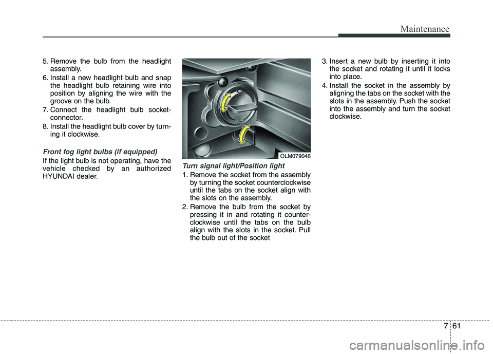
1. Remove the socket from the assembly by turning the socket counterclockwise
until the tabs on the socket align with
the slots on the assembly.
2. Remove the bulb from the socket by pressing it in and rotating it counter-
clockwise until the tabs on the bulb
align with the slots in the socket. Pull
the bulb out of the socket 3. Insert a new bulb by inserting it into
the socket and rotating it until it locks
into place.
4. Install the socket in the assembly by aligning the tabs on the socket with the
slots in the assembly. Push the socket
into the assembly and turn the socket
clockwise.
OLM079046