2011 Hyundai Sonata Hybrid fuses
[x] Cancel search: fusesPage 15 of 404

H8
The hybrid system caution for safety
THE COMPONENTS OF HYBRID VEHICLE (CONT.)
WARNING
In the hybrid system, the hybrid
battery uses high voltage to oper-
ate the motor and other compo-
nents. This high voltage hybrid bat-
tery system can be very dangerous.
Never touch the hybrid system. If
you touch the hybrid battery sys-
tem, serious injury or death may
occur.
WARNING
The high voltage warning label is
attached to the components of high
voltage is orange. Never touch the
wires, cables and connectors as
possible. If not, serious injury or
death causes.
WARNING
When you replace the fuses, Be
careful the HPCU. Never touch the
HPCU. If not, it may result in HPCU
warning.
OYFH021005N
OYFH021004N
OYFH021002N
WARNING
• Do not disassemble the high volt-
age motor connector. If not, it
may result in death or serious
injury.
Your vehicle's hybrid system
should only be inspected or
repaired by an authorized
Hyundai dealer.
Page 17 of 404

H10
Service plug
This service plug (1) located in the rear
trunk as shown should always be pulled
out to disconnect and turn off the hybrid
system.
IMPORTANT: Wait 5 minutes after this
lever is disconnected to work on the
car to assure all remaining charge in
the system has dissipated.
THE COMPONENTS OF HYBRID VEHICLE (CONT.)
WARNING
This hybrid vehicle uses the hybrid
battery system inverter and con-
verter to generate high voltage.
High voltage in the hybrid battery
system is very dangerous and can
cause severe burns and electric
shock. This may result in serious
injury or death.
For your safety, never touch,
replace, dismantle or remove the
hybrid battery system including
components, cables and connec-
tors. Severe burns or electric
shock may result in serious
injury or death if you do not fol-
low this warning.
When the hybrid battery system
operates, the hybrid battery sys-
tem can be hot. Always be care-
ful because burns or electric
shock maybe caused by high
voltage.
Do not drop water or liquid to
HPCU, HSG, Motor and fuses. The
hybrid system components are
covered, If you drop water or liq-
uid to hybrid system components,
it may result in electronic shock.
WARNING
This plug is attached to the hybrid
battery system, which contains
very dangerous high voltage.
Touching the service lever may
cause severe burns or electric
shock. When you touch it, be care-
ful not to damage.
OYFH061020N
Page 202 of 404
Features of your vehicle
108 4
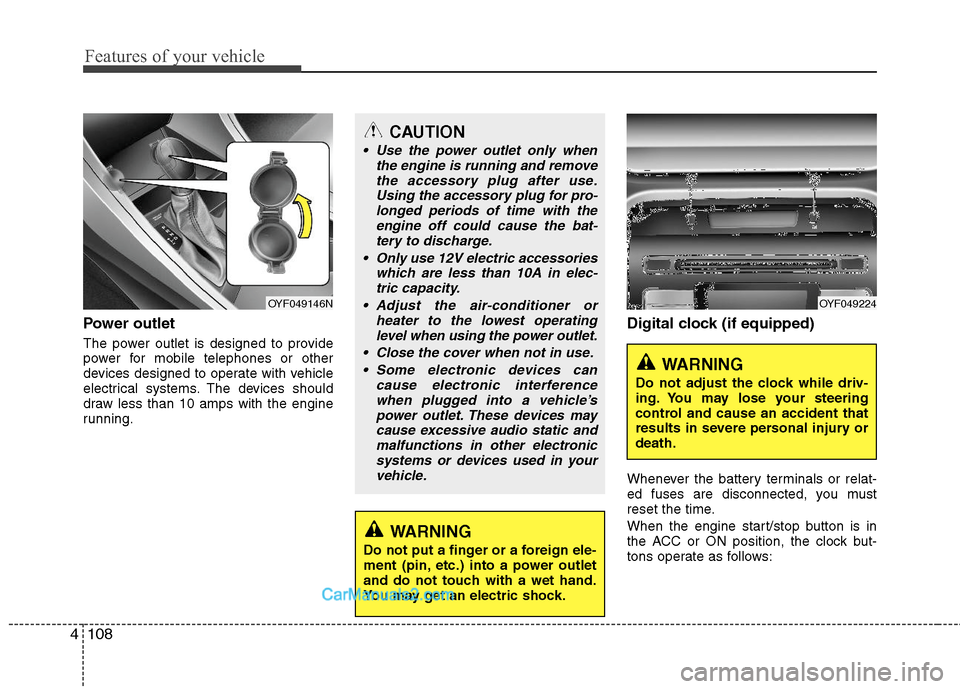
Power outlet
The power outlet is designed to provide
power for mobile telephones or other
devices designed to operate with vehicle
electrical systems. The devices should
draw less than 10 amps with the engine
running.
Digital clock (if equipped)
Whenever the battery terminals or relat-
ed fuses are disconnected, you must
reset the time.
When the engine start/stop button is in
the ACC or ON position, the clock but-
tons operate as follows:
CAUTION
Use the power outlet only when
the engine is running and remove
the accessory plug after use.
Using the accessory plug for pro-
longed periods of time with the
engine off could cause the bat-
tery to discharge.
Only use 12V electric accessories
which are less than 10A in elec-
tric capacity.
Adjust the air-conditioner or
heater to the lowest operating
level when using the power outlet.
Close the cover when not in use.
Some electronic devices can
cause electronic interference
when plugged into a vehicle’s
power outlet. These devices may
cause excessive audio static and
malfunctions in other electronic
systems or devices used in your
vehicle.
WARNING
Do not put a finger or a foreign ele-
ment (pin, etc.) into a power outlet
and do not touch with a wet hand.
You may get an electric shock.
OYF049146NOYF049224
WARNING
Do not adjust the clock while driv-
ing. You may lose your steering
control and cause an accident that
results in severe personal injury or
death.
Page 307 of 404

7
Engine compartment / 7-2
Maintenance services / 7-3
Owner maintenance / 7-5
Scheduled maintenance service / 7-7
Explanation of scheduled maintenance items / 7-19
Engine oil / 7-22
Inverter coolant / 7-24
Engine coolant / 7-24
Brake fluid / 7-27
Washer fluid / 7-28
Parking brake / 7-28
Air cleaner / 7-29
Climate control air filter / 7-30
Wiper blades / 7-32
Battery / 7-34
Tires and wheels / 7-37
Fuses / 7-50
Light bulbs / 7-60
Appearance care / 7-69
Emission control system / 7-75
California perchlorate notice / 7-78
Maintenance
Page 356 of 404

Maintenance
50 7
FUSES
A vehicle’s electrical system is protected
from electrical overload damage by
fuses.This vehicle has 2 fuse panels, one locat-
ed in the driver’s side panel bolster, the
other in the engine compartment.
If any of your vehicle’s lights, acces-
sories, or controls do not work, check the
appropriate circuit fuse. If a fuse has
blown, the element inside the fuse will be
melted.
If the electrical system does not work,
first check the driver’s side fuse panel.
Always replace a blown fuse with one of
the same rating.
If the replacement fuse blows, this indi-
cates an electrical problem. Avoid using
the system involved and immediately
consult an authorized HYUNDAI dealer.
Three kinds of fuses are used: blade type
for lower amperage rating, cartridge type,
and multi fuse for higher amperage rat-
ings.
OBK079042 Normal Normal Blade type
Cartridge type
Multi fuseBlown
Blown
Normal Blown
WARNING - Fuse replace-
ment
Never replace a fuse with any-
thing but another fuse of the
same rating.
A higher capacity fuse could
cause damage and possibly a
fire.
Never install a wire instead of the
proper fuse - even as a temporary
repair. It may cause extensive
wiring damage and a possible fire.
CAUTION
Do not use a screwdriver or any
other metal object to remove fuses
because it may cause a short circuit
and damage the system.
Page 357 of 404
751
Maintenance
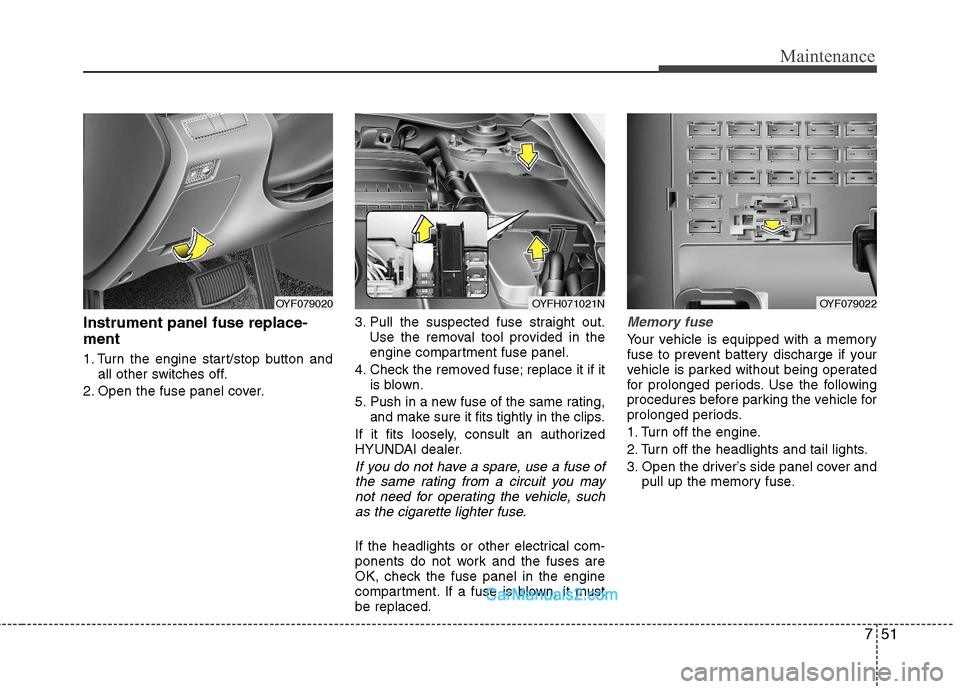
Instrument panel fuse replace-
ment
1. Turn the engine start/stop button and
all other switches off.
2. Open the fuse panel cover.3. Pull the suspected fuse straight out.
Use the removal tool provided in the
engine compartment fuse panel.
4. Check the removed fuse; replace it if it
is blown.
5. Push in a new fuse of the same rating,
and make sure it fits tightly in the clips.
If it fits loosely, consult an authorized
HYUNDAI dealer.
If you do not have a spare, use a fuse of
the same rating from a circuit you may
not need for operating the vehicle, such
as the cigarette lighter fuse.
If the headlights or other electrical com-
ponents do not work and the fuses are
OK, check the fuse panel in the engine
compartment. If a fuse is blown, it must
be replaced.
Memory fuse
Your vehicle is equipped with a memory
fuse to prevent battery discharge if your
vehicle is parked without being operated
for prolonged periods. Use the following
procedures before parking the vehicle for
prolonged periods.
1. Turn off the engine.
2. Turn off the headlights and tail lights.
3. Open the driver’s side panel cover and
pull up the memory fuse.
OYF079020OYFH071021NOYF079022
Page 365 of 404

759
Maintenance
Engine compartment sub fuse panel (Sub-relay box) Engine compartment main fuse panel (Engien junction fuses)
Description Fuse rating Protected component
OPCU 80A OPCU Relay
C/FAN 60A C/FAN HI Relay
Relay No. Relay Name Type
E41 ACC Relay PLUG MICRO
E42 RR HTD Relay PLUG MICRO
E43 - PLUG MICRO
E44 C/FAN LO Relay PLUG MICRO
E45 AUX Water Pump Relay PLUG MICRO
E46 - PLUG MICRO
E47 Deicer Relay PLUG MICRO
E48 - PLUG MICRO
E49 IG1 Relay PLUG MICRO
E50 IG2 Relay PLUG MICRO
E51 Wiper Relay PLUG MICRO
E52 T/Turn Door Unlock RelayPLUG MICRO
E53 HAC Realy PLUG MICRO
E54 Blower Relay PLUG MICRO
EMS
BOXRLY.1 Horn Relay PLUG MICRO
RLY.2 F/Pump Relay PLUG MICRO
RLY.3 ECU Relay PLUG MINI
Page 399 of 404

I5
Index
Front seat adjustment ......................................................3-5
Fuel filler lid..................................................................4-31
Fuel gauge ....................................................................4-46
Fuel requirements ............................................................1-3
Fuses ..............................................................................7-49
Fuse/relay panel description ....................................7-53
Instrument panel fuse ..............................................7-50
Main fuse ................................................................7-52
Mode control switch ................................................7-51
Multi fuse ................................................................7-52
Gauge
Engine temperature gauge ......................................4-45
Fuel gauge ..............................................................4-46
Glass antenna ................................................................4-98
Glassroof, see sunroof ..................................................4-34
Glove box ......................................................................4-91
Hazard warning flasher ................................................4-60
Hazardous driving conditions ......................................5-37
Headlight bulb replacement ..........................................7-58
Headrest ..................................................................3-6, 3-9
Highway driving............................................................5-40
Hill-start assist control (HAC) ......................................5-30Hood ..............................................................................4-29
Horn ..............................................................................4-39
How to use this manual ..................................................1-2
Ignition key interlock system ........................................5-19
Immobilizer system ........................................................4-4
Indicator symbols on the instrument cluster ..................1-7
Indicators and warnings ................................................4-50
Inside rearview mirror ..................................................4-40
Instrument cluster ..........................................................4-43
Engine temperature gauge ......................................4-45
Fuel gauge ..............................................................4-46
Instrument panel illumination ................................4-44
Odometer ................................................................4-47
Speedometer ............................................................4-44
Tachometer ..............................................................4-44
Trip computer ..........................................................4-46
Warning and indicators ............................................4-50
Instrument panel fuse ....................................................7-50
Instrument panel illumination ......................................4-44
Instrument panel overview ..............................................2-3
Interior care ..................................................................7-71
Interior features ............................................................4-93
Aux, USB and iPod port..........................................4-97
Clothes hanger ........................................................4-96
Cup holder ..............................................................4-93
G
H
I