Page 366 of 408
747
Maintenance
G210101AXM
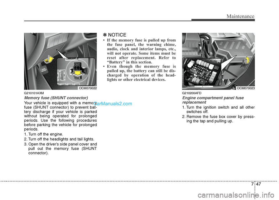
Memory fuse (SHUNT connector)
Your vehicle is equipped with a memory
fuse (SHUNT connector) to prevent bat-
tery discharge if your vehicle is parked
without being operated for prolonged
periods. Use the following procedures
before parking the vehicle for prolonged
periods.
1. Turn off the engine.
2. Turn off the headlights and tail lights.
3. Open the driver’s side panel cover andpull out the memory fuse (SHUNT
connector).
✽ ✽NOTICE
• If the memory fuse is pulled up from
the fuse panel, the warning chime,
audio, clock and interior lamps, etc.,
will not operate. Some items must be
reset after replacement. Refer to
“Battery” in this section.
• Even though the memory fuse is pulled up, the battery can still be dis-
charged by operation of the head-
lights or other electrical devices.
G210200AFD
Engine compartment panel fuse
replacement
1. Turn the ignition switch and all other switches off.
2. Remove the fuse box cover by press- ing the tap and pulling up.
OCM070022
OCM070023
Page 369 of 408
Maintenance
50
7
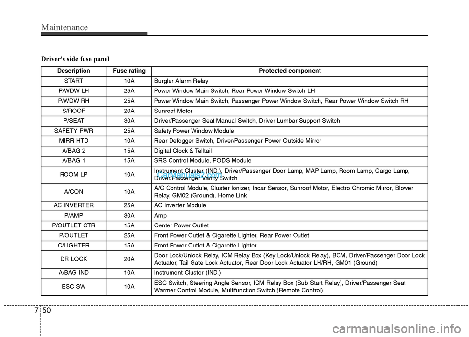
Driver's side fuse panel
Description Fuse rating Protected component
START 10A Burglar Alarm Relay
P/WDW LH 25A Power Window Main Switch, Rear Power Window Switch LH
P/WDW RH 25A Power Window Main Switch, Passenger Power Window Switch, Rear Power Window Switch RH S/ROOF 20A Sunroof MotorP/SEAT 30A Driver/Passenger Seat Manual Switch, Driver Lumbar Support Switch
SAFETY PWR 25A Safety Power Window Module MIRR HTD 10A Rear Defogger Switch, Driver/Passenger Power Outside MirrorA/BAG 2 15A Digital Clock & Telltail
A/BAG 1 15A SRS Control Module, PODS Module
ROOM LP 10A Instrument Cluster (IND.), Driver/Passenger Door Lamp, MAP Lamp, Room Lamp, Cargo Lamp,
Driver/Passenger Vanity Switch
A/CON 10A A/C Control Module, Cluster Ionizer, Incar Sensor, Sunroof Motor, Electro Chromic Mirror, Blower
Relay, GM02 (Ground), Home Link
AC INVERTER 25A AC Inverter Module P/AMP 30A Amp
P/OUTLET CTR 15A Center Power Outlet P/OUTLET 25A Front Power Outlet & Cigarette Lighter, Rear Power Outlet
C/LIGHTER 15A Front Power Outlet & Cigarette Lighter
DR LOCK 20A Door Lock/Unlock Relay, ICM Relay Box (Key Lock/Unlock Relay), BCM, Driver/Passenger Door Lock
Actuator, Tail Gate Lock Actuator, Rear Door Lock Actuator LH/RH, GM01 (Ground)
A/BAG IND 10A Instrument Cluster (IND.)
ESC SW10AESC Switch, Steering Angle Sensor, ICM Relay Box (Sub Start Relay), Driver/Passenger Seat
Warmer Control Module, Multifunction Switch (Remote Control)
Page 370 of 408
751
Maintenance
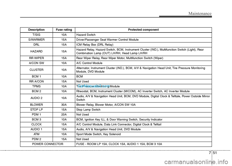
Description Fuse ratingProtected component
T/SIG 10A Hazard Switch
S/WARMER 15A Driver/Passenger Seat Warmer Control Module DRL 15A ICM Relay Box (DRL Relay)
HAZARD 15A Hazard Relay, Hazard Switch, BCM, Instrument Cluster (IND.), Multifunction Switch (Light), Rear
Combination Lamp (OUT) LH/RH, Head Lamp LH/RH
RR WIPER 15A Rear Wiper Relay, Rear Wiper Motor, Multifunction Switch (Wiper)
A/CON SW 10A A/C Control Module
CLUSTER 10A Alternator, Instrument Cluster (IND.), BCM, A/V & Navigation Head Unit, Tire Pressure Monitoring
Module, DVD Module
BCM 1 10A BCM
RR A/CON 15A Not Used TPMS 10A Tire Pressure Monitoring Module
BCM 2 10A Rheostat, BCM, Instrument Cluster (MICOM), AC Inverter Switch, AC Inverter Module
AUDIO 2 10A Audio, A/V & Navigation Head Unit, BCM, DVD Module, Digital Clock & Telltale, Power Outside Mirror
Switch
BLOWER 30A Blower Relay, Blower Motor, A/CON SW 10A STOP LP 15A Stop Lamp Switch PDM 1 20A Not Used
BCM 3 10A BCM, Ignition Key ILL. & Door Warning Switch, Security Indicator
CLOCK 15A A/C Control Module, Data Link Connector, Digital Clock & Telltail
AUDIO 1 15A Audio, A/V & Navigation Head Unit, DVD Module ATM 10A Sport Mode Switch, Key Solenoid
PDM 2 15A Not Used POWER CONNECTOR FUSE - ROOM LP 15A, CLOCK 15A, AUDIO 1 15A, BCM 3 10A
Page 371 of 408
Maintenance
52
7
Engine compartment
Description Fuse rating Protected component
ALT 175A FUSIBLE LINK - BLR, B+ 2, P/WDW, ESC 1, ESC 2
FUSE - DEICER, RR HTD, A/CON, FR FOG, H/LP LO LH, H/LP LO RH
BATT 30A Trailer Power Outlet
IGN 1 40A Ignition Switch (ACC, IG 1)
ESC 1 40A Multipurpose Check Connector, ESC Control Module
CON FAN 2 50A Condenser Fan Relay (High) ESC 2 20A ESC Control ModuleBLR 40A FUSE - BLOWER
P/WDW 40A Power Window Relay, FUSE - SAFETY PWR B+ 2 50A FUSE - P/SEAT, TPMS, RR A/CON, S/WARMER, S/ROOF, PDM 2, P/AMP, AC INVERTER, DRL
IGN 2 40A Ignition Switch (START, IG 2), Start Relay
B+ 1 50A FUSE - DR LOCK, HAZARD, ATM, PDM 1, STOP LP, POWER CONNECTOR (BCM 3, CLOCK
ROOM LP, AUDIO 1)
CON FAN 1 40A Condenser Fan Relay (Low) ECU MAIN 40A Engine Control Relay
1 DEICER 15A Front Wiper Deicer Relay
2 RR HTD 30A Rear Defogger Relay
3- --
4 H/LP LO RH 15A Head Lamp Low Relay (RH)
5 HORN 15A Horn Relay
Page 376 of 408
757
Maintenance
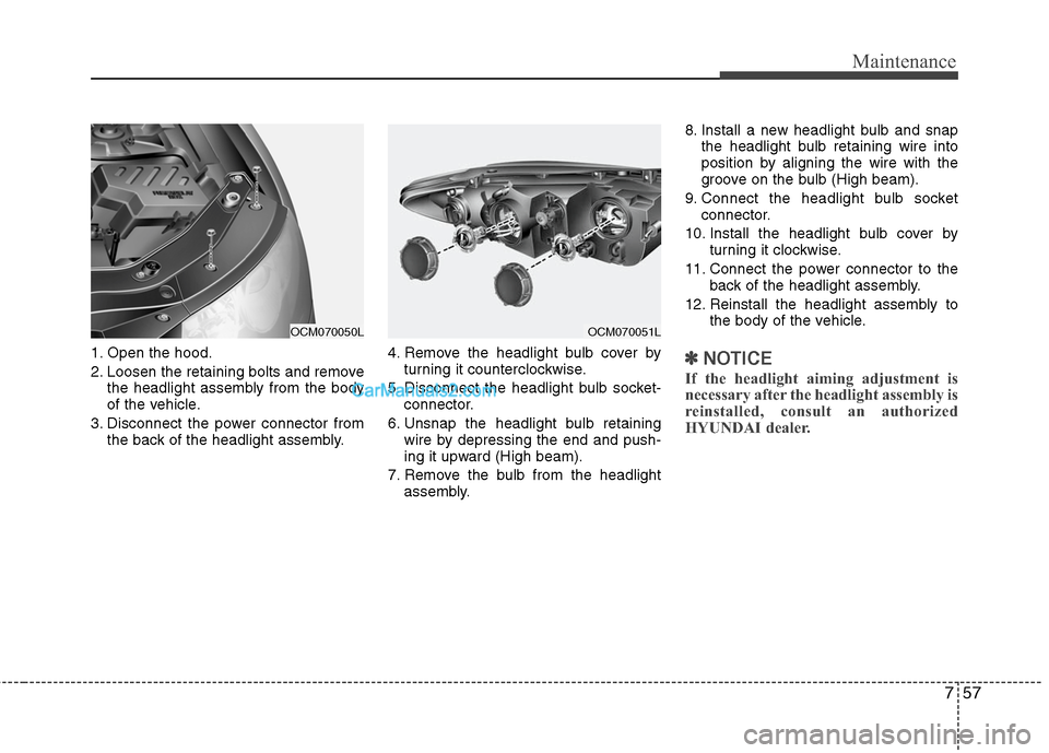
1. Open the hood.
2. Loosen the retaining bolts and removethe headlight assembly from the body
of the vehicle.
3. Disconnect the power connector from the back of the headlight assembly. 4. Remove the headlight bulb cover by
turning it counterclockwise.
5. Disconnect the headlight bulb socket- connector.
6. Unsnap the headlight bulb retaining wire by depressing the end and push-
ing it upward (High beam).
7. Remove the bulb from the headlight assembly. 8. Install a new headlight bulb and snap
the headlight bulb retaining wire into
position by aligning the wire with the
groove on the bulb (High beam).
9. Connect the headlight bulb socket connector.
10. Install the headlight bulb cover by turning it clockwise.
11. Connect the power connector to the back of the headlight assembly.
12. Reinstall the headlight assembly to the body of the vehicle.✽ ✽NOTICE
If the headlight aiming adjustment is
necessary after the headlight assembly is
reinstalled, consult an authorized
HYUNDAI dealer.
OCM070051L
OCM070050L
Page 377 of 408
Maintenance
58
7
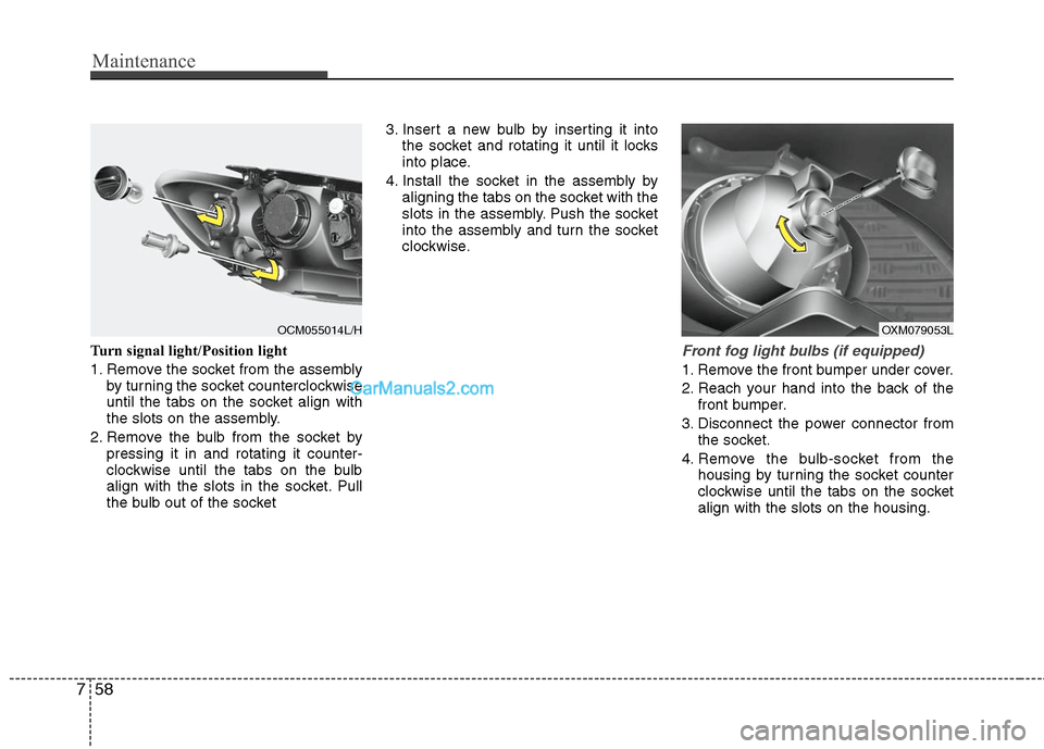
Turn signal light/Position light
1. Remove the socket from the assembly
by turning the socket counterclockwise
until the tabs on the socket align with
the slots on the assembly.
2. Remove the bulb from the socket by pressing it in and rotating it counter-
clockwise until the tabs on the bulb
align with the slots in the socket. Pull
the bulb out of the socket 3. Insert a new bulb by inserting it into
the socket and rotating it until it locks
into place.
4. Install the socket in the assembly by aligning the tabs on the socket with the
slots in the assembly. Push the socket
into the assembly and turn the socket
clockwise.Front fog light bulbs (if equipped)
1. Remove the front bumper under cover.
2. Reach your hand into the back of thefront bumper.
3. Disconnect the power connector from the socket.
4. Remove the bulb-socket from the housing by turning the socket counter
clockwise until the tabs on the socket
align with the slots on the housing.
OXM079053L
OCM055014L/H
Page 378 of 408
759
Maintenance
5. Install the new bulb-socket into thehousing by aligning the tabs on the
socket with the slots in the housing.
Push the socket into the housing and
turn the socket clockwise.
6. Connect the power connector to the socket.
7. Reinstall the front bumper under cover.
Rear combination light bulb
replacement
(1) Rear turn signal light
(2) Stop and tail light
(3) Tail light
(4) Back-up light
(5) Rear side marker
Outside light
1. Open the tailgate.
2. Remove the service cover using a flat- blade screwdriver.
3. Loosen the light assembly retaining nuts with a wrench.
4. Remove the rear combination light assembly from the body of the vehicle.
OCM055026
OCM070033
OCM070052N
Page 379 of 408
Maintenance
60
7
5. Remove the socket from the assembly
by turning the socket counterclockwise
until the tabs on the socket align with
the slots on the assembly.
6. Remove the bulb from the socket by pressing it in and rotating it counter-
clockwise until the tabs on the bulb align
with the slots in the socket. Pull the bulb
out of the socket. (Side marker :
Remove the bulb from the socket by
pulling it out)
7. Insert a new bulb by inserting it into the socket and rotating it until it locks
into place.
8. Install the socket in the assembly by aligning the tabs on the socket with the
slots in the assembly. Push the socket
into the assembly and turn the socket
clockwise.
9. Reinstall the light assembly to the body of the vehicle.
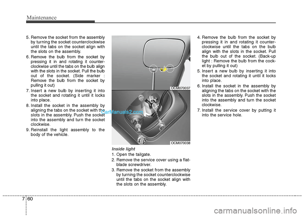
Inside light
1. Open the tailgate.
2. Remove the service cover using a flat-blade screwdriver.
3. Remove the socket from the assembly by turning the socket counterclockwise
until the tabs on the socket align with
the slots on the assembly. 4. Remove the bulb from the socket by
pressing it in and rotating it counter-
clockwise until the tabs on the bulb
align with the slots in the socket. Pull
the bulb out of the socket. (Back-up
light : Remove the bulb from the cock-
et by pulling it out)
5. Insert a new bulb by inserting it into the socket and rotating it until it locks
into place.
6. Install the socket in the assembly by aligning the tabs on the socket with the
slots in the assembly. Push the socket
into the assembly and turn the socket
clockwise.
7. Install the service cover by putting it into the service hole.
OCM070037
OCM070038