2011 Hyundai Santa Fe power steering
[x] Cancel search: power steeringPage 15 of 408
Your vehicle at a glance
2
2
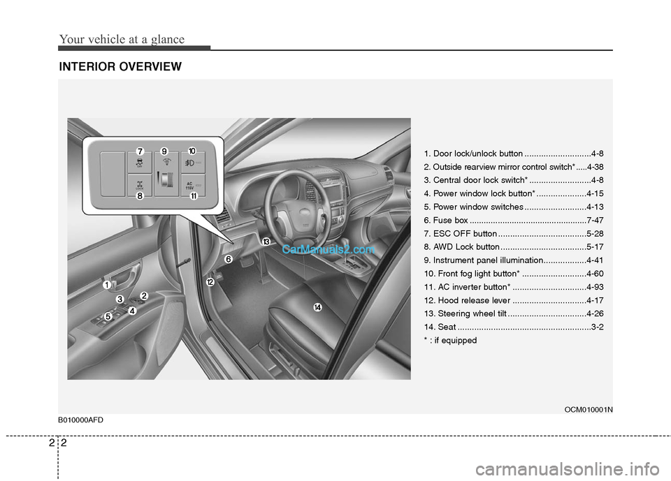
INTERIOR OVERVIEW
1. Door lock/unlock button ............................4-8
2. Outside rearview mirror control switch* .....4-38
3. Central door lock switch* ..........................4-8
4. Power window lock button* .....................4-15
5. Power window switches ..........................4-13
6. Fuse box ..................................................7-47
7. ESC OFF button .....................................5-28
8. AWD Lock button ....................................5-17
9. Instrument panel illumination..................4-41
10. Front fog light button* ...........................4-60
11. AC inverter button* ...............................4-93
12. Hood release lever ...............................4-17
13. Steering wheel tilt .................................4-26
14. Seat ........................................................3-2
* : if equipped
OCM010001N
B010000AFD
Page 16 of 408
23
Your vehicle at a glance
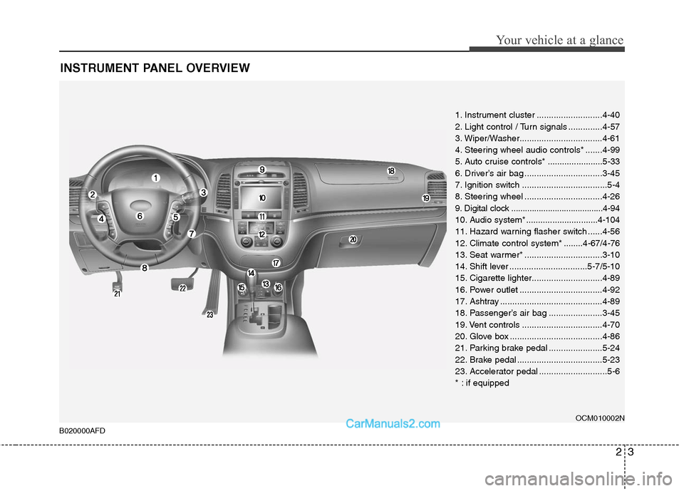
INSTRUMENT PANEL OVERVIEW
1. Instrument cluster ...........................4-40
2. Light control / Turn signals ..............4-57
3. Wiper/Washer..................................4-61
4. Steering wheel audio controls* .......4-99
5. Auto cruise controls* .......................5-33
6. Driver’s air bag ................................3-45
7. Ignition switch ...................................5-4
8. Steering wheel ................................4-26
9. Digital clock ........................................4-94
10. Audio system*..............................4-104
11. Hazard warning flasher switch ......4-56
12. Climate control system * ........4-67/4-76
13. Seat warmer* ................................3-10
14. Shift lever ................................5-7/5-10
15. Cigarette lighter.............................4-89
16. Power outlet ..................................4-92
17. Ashtray ..........................................4-89
18. Passenger’s air bag ......................3-45
19. Vent controls .................................4-70
20. Glove box ......................................4-86
21. Parking brake pedal ......................5-24
22. Brake pedal ...................................5-23
23. Accelerator pedal ............................5-6
* : if equipped
OCM010002N
B020000AFD
Page 17 of 408
Your vehicle at a glance
4
2
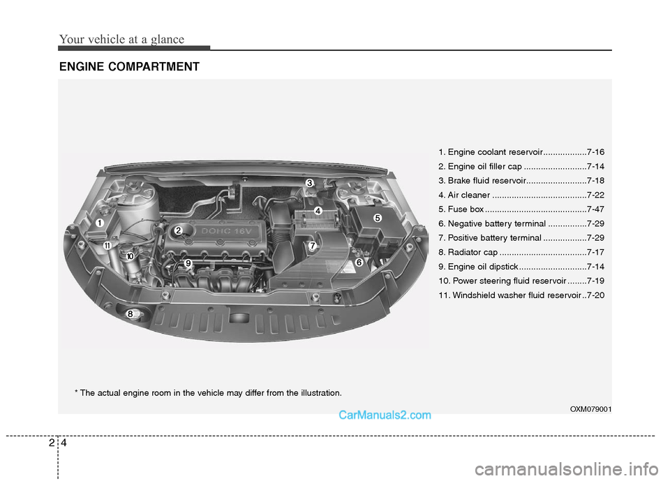
ENGINE COMPARTMENT
OXM079001
1. Engine coolant reservoir ..................7-16
2. Engine oil filler cap ..........................7-14
3. Brake fluid reservoir.........................7-18
4. Air cleaner .......................................7-22
5. Fuse box ..........................................7-47
6. Negative battery terminal ................7-29
7. Positive battery terminal ..................7-29
8. Radiator cap ....................................7-17
9. Engine oil dipstick ............................7-14
10. Power steering fluid reservoir ........7-19
11. Windshield washer fluid reservoir ..7-20
* The actual engine room in the vehicle may differ from the illustration.
Page 23 of 408
Safety system of your vehicle
6
3
CAUTION
The power seat is driven by an
electric motor. Stop operatingonce the adjustment is complet- ed. Excessive operation maydamage the electrical equipment.
When in operation, the power seat consumes a large amount ofelectrical power. To preventunnecessary charging system drain, don’t adjust the power seatlonger than necessary while the engine is not running.
Do not operate two or more power seat control switches at the sametime. Doing so may result inpower seat motor or electricalcomponent malfunction.
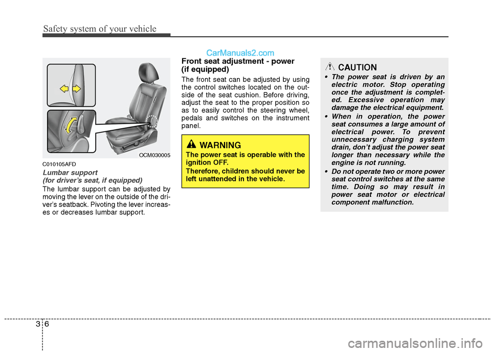
C010105AFD
Lumbar support (for driver’s seat, if equipped)
The lumbar support can be adjusted by
moving the lever on the outside of the dri-
ver’s seatback. Pivoting the lever increas-
es or decreases lumbar support.
Front seat adjustment - power
(if equipped)
The front seat can be adjusted by using
the control switches located on the out-
side of the seat cushion. Before driving,
adjust the seat to the proper position so
as to easily control the steering wheel,
pedals and switches on the instrument
panel.
OCM030005
WARNING
The power seat is operable with the
ignition OFF.
Therefore, children should never be
left unattended in the vehicle.
Page 105 of 408
Features of your vehicle
26
4
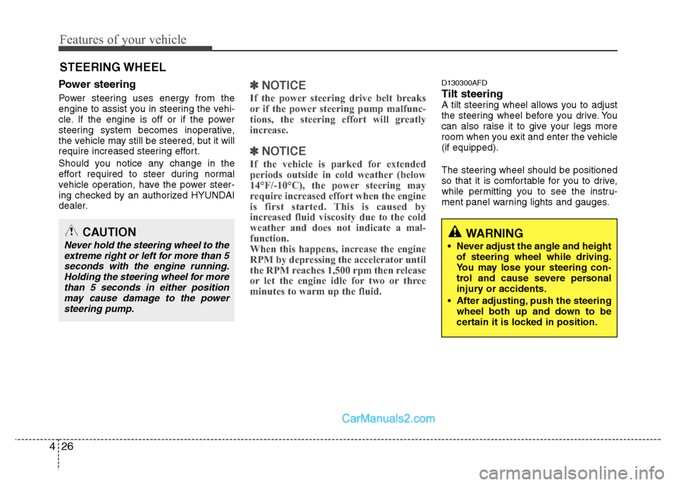
WARNING
Never adjust the angle and height
of steering wheel while driving.
You may lose your steering con-
trol and cause severe personal
injury or accidents.
After adjusting, push the steering wheel both up and down to be
certain it is locked in position.
Power steering
Power steering uses energy from the
engine to assist you in steering the vehi-
cle. If the engine is off or if the power
steering system becomes inoperative,
the vehicle may still be steered, but it will
require increased steering effort.
Should you notice any change in the
effort required to steer during normal
vehicle operation, have the power steer-
ing checked by an authorized HYUNDAI
dealer.
✽ ✽ NOTICE
If the power steering drive belt breaks
or if the power steering pump malfunc-
tions, the steering effort will greatly
increase.
✽ ✽NOTICE
If the vehicle is parked for extended
periods outside in cold weather (below
14°F/-10°C), the power steering may
require increased effort when the engine
is first started. This is caused by
increased fluid viscosity due to the cold
weather and does not indicate a mal-
function.
When this happens, increase the engine
RPM by depressing the accelerator until
the RPM reaches 1,500 rpm then release
or let the engine idle for two or three
minutes to warm up the fluid.
D130300AFD
Tilt steering A tilt steering wheel allows you to adjust
the steering wheel before you drive. You
can also raise it to give your legs more
room when you exit and enter the vehicle
(if equipped).
The steering wheel should be positioned
so that it is comfortable for you to drive,
while permitting you to see the instru-
ment panel warning lights and gauges.
STEERING WHEEL
CAUTION
Never hold the steering wheel to the
extreme right or left for more than 5seconds with the engine running.Holding the steering wheel for more than 5 seconds in either positionmay cause damage to the power steering pump.
Page 108 of 408
429
Features of your vehicle
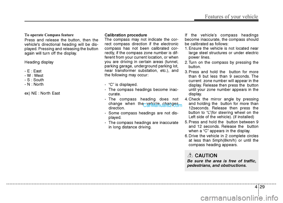
To operate Compass feature
Press and release the button, then the
vehicle's directional heading will be dis-
played. Pressing and releasing the button
again will turn off the display.
Heading display
- E : East
- W : West
- S : South
- N : North
ex) NE : North EastCalibration procedure
The compass may not indicate the cor-
rect compass direction if the electronic
compass has not been calibrated cor-
rectly, if the compass zone number is dif-
ferent from your current location, or when
you are driving in certain areas (tunnel,
parking garage, underground parking lot,
near transformer substation, etc.), and
the following may occur:
- “C” is displayed.
- The compass headings become inac-
curate.
- The compass heading does not change when the vehicle changes
direction.
- Some compass headings are not dis- played.
- The compass headings are inaccurate in long distance driving. If the vehicle’s compass headings
become inaccurate, the compass should
be calibrated as follows:
1. Ensure the vehicle is not located near
large steel structures or under electric
power lines.
2. Turn on the compass by pressing the button.
3. Press and hold the button for more than 6 but less than 9 seconds. The
current zone number will appear in the
display. Release then press the button
until your zone number appears in the
display.
4. Check the mirror angle by pressing and holding the button for more than
12seconds. Release then press the
button to “L”(for steering wheel on the
Left side of the vehicle). (if installed)
5. Press and hold the button between 9 and 12 seconds. Release the button
when a “C” appears in the display.
6. Drive the vehicle in 2 complete circles at less than 5mph(8km/h) or until the
compass heading appears.
CAUTION
Be sure the area is free of traffic,pedestrians, and obstructions.
Page 133 of 408
Features of your vehicle
54
4
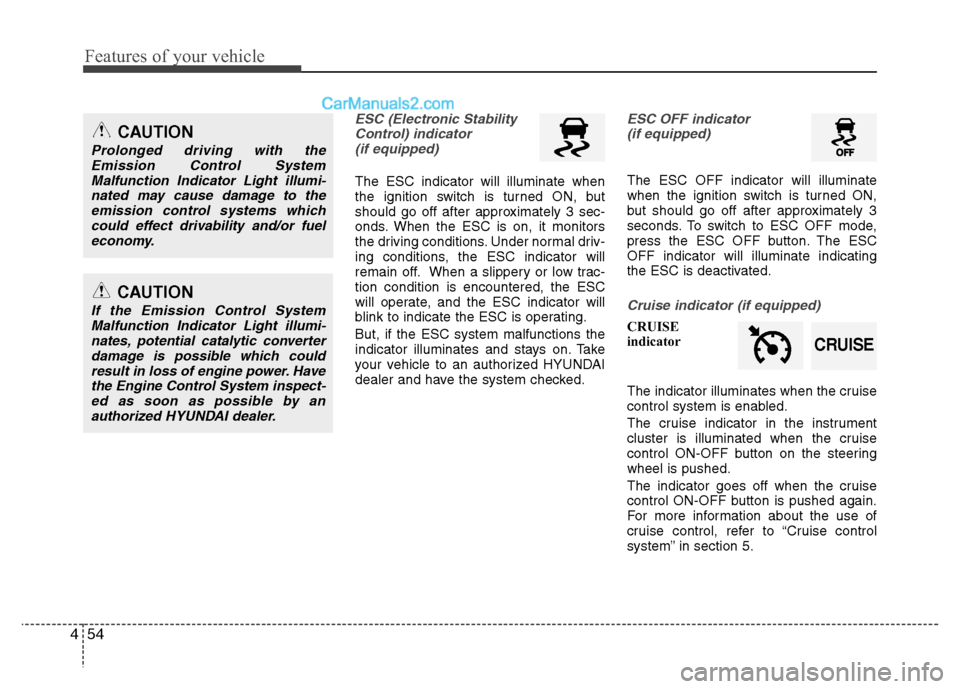
ESC (Electronic Stability
Control) indicator(if equipped)
The ESC indicator will illuminate when
the ignition switch is turned ON, but
should go off after approximately 3 sec-
onds. When the ESC is on, it monitors
the driving conditions. Under normal driv-
ing conditions, the ESC indicator will
remain off. When a slippery or low trac-
tion condition is encountered, the ESC
will operate, and the ESC indicator will
blink to indicate the ESC is operating.
But, if the ESC system malfunctions the
indicator illuminates and stays on. Take
your vehicle to an authorized HYUNDAI
dealer and have the system checked.
ESC OFF indicator (if equipped)
The ESC OFF indicator will illuminate
when the ignition switch is turned ON,
but should go off after approximately 3
seconds. To switch to ESC OFF mode,
press the ESC OFF button. The ESC
OFF indicator will illuminate indicating
the ESC is deactivated.
Cruise indicator (if equipped)
CRUISE
indicator
The indicator illuminates when the cruise
control system is enabled.
The cruise indicator in the instrument
cluster is illuminated when the cruise
control ON-OFF button on the steering
wheel is pushed.
The indicator goes off when the cruise
control ON-OFF button is pushed again.
For more information about the use of
cruise control, refer to “Cruise control
system” in section 5.
CAUTION
Prolonged driving with the
Emission Control SystemMalfunction Indicator Light illumi-nated may cause damage to theemission control systems whichcould effect drivability and/or fuel economy.
CAUTION
If the Emission Control SystemMalfunction Indicator Light illumi-nates, potential catalytic converterdamage is possible which couldresult in loss of engine power. Havethe Engine Control System inspect- ed as soon as possible by anauthorized HYUNDAI dealer.
CRUISE
Page 250 of 408
Driving your vehicle
16
5
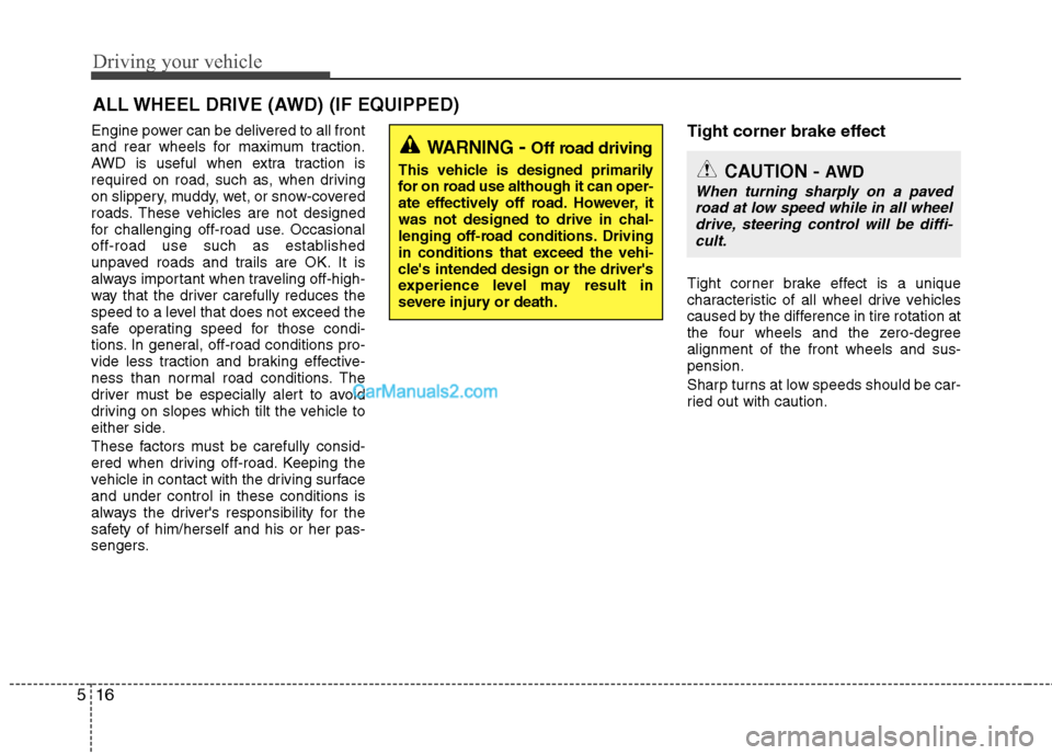
Engine power can be delivered to all front
and rear wheels for maximum traction.
AWD is useful when extra traction is
required on road, such as, when driving
on slippery, muddy, wet, or snow-covered
roads. These vehicles are not designed
for challenging off-road use. Occasional
off-road use such as established
unpaved roads and trails are OK. It is
always important when traveling off-high-
way that the driver carefully reduces the
speed to a level that does not exceed the
safe operating speed for those condi-
tions. In general, off-road conditions pro-
vide less traction and braking effective-
ness than normal road conditions. The
driver must be especially alert to avoid
driving on slopes which tilt the vehicle to
either side.
These factors must be carefully consid-
ered when driving off-road. Keeping the
vehicle in contact with the driving surface
and under control in these conditions is
always the driver's responsibility for the
safety of him/herself and his or her pas-
sengers.Tight corner brake effect
Tight corner brake effect is a unique
characteristic of all wheel drive vehicles
caused by the difference in tire rotation at
the four wheels and the zero-degree
alignment of the front wheels and sus-
pension.
Sharp turns at low speeds should be car-
ried out with caution.
ALL WHEEL DRIVE (AWD) (IF EQUIPPED)
WARNING- Off road driving
This vehicle is designed primarily
for on road use although it can oper-
ate effectively off road. However, it
was not designed to drive in chal-
lenging off-road conditions. Driving
in conditions that exceed the vehi-
cle's intended design or the driver's
experience level may result in
severe injury or death.CAUTION - AW D
When turning sharply on a paved
road at low speed while in all wheeldrive, steering control will be diffi-cult.