2011 Hyundai H-1 (Grand Starex) ESP
[x] Cancel search: ESPPage 310 of 338

Maintenance
56 7
Instrument panel fuse panel
Description Fuse rating Protected component
AUDIO-2 10A Audio, Digital clock, BCM, Power outside mirror switch
C/LIGHTER 20A Cigarette lighter, Front power outlet
S/HTD DRI 10A Driver seat warmer switch (if equipped)
DRL 10A BCM (if equipped)
RR FOG LP 15A Rear fog lamp relay
H/LP 10A Head lamp High/Low relay
FRT WIPER 25A Front wiper relay, Front wiper motor
BCM 10A BCM
HTR 10A Front/Rear blower relay, Front/Rear A/C control module, Condenser fan relay, Electro chromic mirror, Thermo
switch, PTC heater relay(D4CB), EGR solenoid valve(D4BH)
B/UP LP 10A Back-up lamp relay, Back-up lamp switch, Transmission range switch
ABS 10A ABS/ESP control module, ESP switch(D4CB)
T/SIG LP 10A Hazard switch
A/BAG 10A SRS control module
A/BAG IND 10A Instrument cluster
CLUSTER 10A Instrument cluster, BCM, Immobilizer control module(D4BH), A/C relay(D4BH), Generator resister
ECU 10A Vehicle speed sensor, ECM, Air flow sensor(D4CB), Injection pump(D4BH), TCM, Fuel filter warning sensor
START 10A Start relay, Burglar alarm relay
MIRR HTD 10A Front A/C control module, Power outside mirror & defogger LH/RH
STOP LP 15A Stop lamp switch
BWS 10A Buzzer
Page 313 of 338

759
Maintenance
Description Fuse rating Protected component
TAIL RH 10A Head lamp RH(Position lamp), Rear combi lamp RH, License lamp RH
H/LP LO LH 10A Head lamp LH
H/LP LO RH 10A Head lamp RH
SNSR 1 10A A/C relay, Condenser fan relay(D4CB), Lambda sensor(D4CB), PTC heater relay #1(D4CB), Stop lamp
switch(D4CB)
SNSR 2 15A D4CB:Camshaft position sensor, Glow plug relay, EGR actuator, VGT control valve, Immobilizer control module
G4KC:Fuel pump relay, Canister purge solenoid valve, Oil control valve, Crankshaft position sensor, Oxygen
sensor, Immobilizer control module, Idle speed control actuator
IGN COIL 15A Ignition coil #1~#4(G4KC), Condenser(G4KC)
ECU 1 10A ECM(D4CB)
ECU 2 20A ECM(D4CB, G4KC), Injector #1~#4(G4KC)
SAFETY P/WDW 20A Safety power window
Engine compartment sub fuse panel (Diesel engine)
Description Fuse rating Protected component
GLOW 80A Glow plug relay
PTC 1 40A PTC heater relay #1
PTC 2 40A PTC heater relay #2
PTC 3 40A PTC heater relay #3
ABS 1 40A ABS/ESP control module
ABS 2 40A ABS/ESP control module
GLOW 10A ECM (D4BH)
Page 314 of 338

Maintenance
60 7
LIGHT BULBS
G220000AEN
Use only the bulbs of the specified
wattage.
✽NOTICE
After heavy, driving rain or washing,
headlight and taillight lenses could
appear frosty. This condition is caused by
the temperature difference between the
lamp inside and outside. This is similar
to the condensation on your windows
inside your vehicle during the rain and
doesn’t indicate a problem with your
vehicle. If the water leaks into the lamp
bulb circuitry, have the vehicle checked
by an authorized HYUNDAI dealer.
G220100AUN
Headlight, position light, turn sig-
nal light, front fog light bulb
replacement
(1) Headlight (High)
(2) Headlight (Low)
(3) Position light
(4) Front turn signal light
(5) Front fog light (if equipped)
WARNING - Working on
the lights
Prior to working on the light, firmly
apply the parking brake, ensure
that the ignition switch is turned to
the LOCK position and turn off the
lights to avoid sudden movement
of the vehicle and burning your fin-
gers or receiving an electric shock.
CAUTION
Be sure to replace the burned-out
bulb with one of the same wattage
rating. Otherwise, it may cause
damage to the fuse or electric
wiring system.
CAUTION
If you don’t have necessary tools,
the correct bulbs and the expertise,
consult an authorized HYUNDAI
dealer. In many cases, it is difficult
to replace vehicle light bulbs
because other parts of the vehicle
must be removed before you can
get to the bulb. This is especially
true if you have to remove the head-
light assembly to
get to the bulb(s).
Removing/installingthe headlight
assembly can result in damage to
the vehicle.OTQ077049
Page 321 of 338

767
Maintenance
Exterior care
G230101AUN
Exterior general caution
It is very important to follow the label
directions when using any chemical
cleaner or polish. Read all warning and
caution statements that appear on the
label.
G230102CEN
Finish maintenance
Washing
To help protect your vehicle’s finish from
rust and deterioration, wash it thoroughly
and frequently at least once a month with
lukewarm or cold water.
If you use your vehicle for off-road driv-
ing, you should wash it after each off-
road trip. Pay special attention to the
removal of any accumulation of salt, dirt,
mud, and other foreign materials. Make
sure the drain holes in the lower edges of
the doors and rocker panels are kept
clear and clean.
Insects, tar, tree sap, bird droppings,
industrial pollution and similar deposits
can damage your vehicle’s finish if not
removed immediately.
Even prompt washing with plain water
may not completely remove all these
deposits. A mild soap, safe for use on
painted surfaces, may be used.After washing, rinse the vehicle thor-
oughly with lukewarm or cold water. Do
not allow soap to dry on the finish.
APPEARANCE CARE
WARNING - Wet brakes
After washing the vehicle, test the
brakes while driving slowly to see if
they have been affected by water. If
braking performance is impaired,
dry the brakes by applying them
lightly while maintaining a slow for-
ward speed.
OJB037800
CAUTION
• Do not use strong soap, chemical
detergents or hot water, and do
not wash the vehicle in direct
sunlight or when the body of the
vehicle is warm.
• Be careful when washing the side
windows of your vehicle.
Especially, with high-pressure
water. Water may leak through the
windows and wet the interior.
• To prevent damage to the plastic
parts and lamps, do not clean
with chemical solvents or strong
detergents.
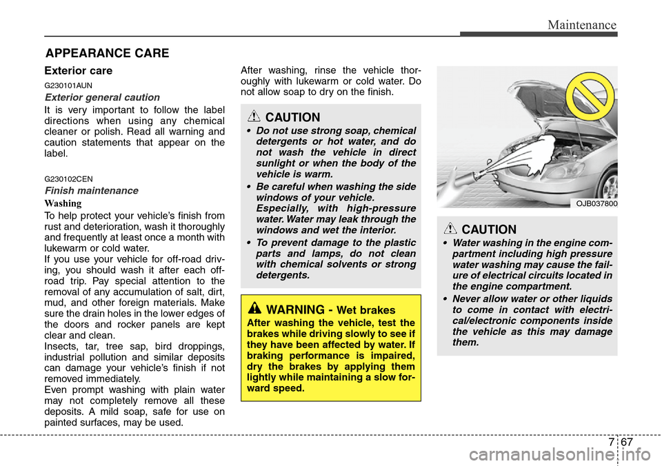
CAUTION
• Water washing in the engine com-
partment including high pressure
water washing may cause the fail-
ure of electrical circuits located in
the engine compartment.
• Never allow water or other liquids
to come in contact with electri-
cal/electronic components inside
the vehicle as this may damage
them.
Page 326 of 338

Maintenance
72 7
EMISSION CONTROL SYSTEM (IF EQUIPPED)
G270000AEN
The emission control system of your
vehicle is covered by a written limited
warranty. Please see the warranty infor-
mation contained in the Service Passport
in your vehicle.
Your vehicle is equipped with an emis-
sion control system to meet all applicable
emission regulations.
There are three emission control sys-
tems, as follows.
(1) Crankcase emission control system
(2) Evaporative emission control system
(3) Exhaust emission control system
In order to assure the proper function of
the emission control systems, it is rec-
ommended that you have your car
inspected and maintained by an author-
ized HYUNDAI dealer in accordance with
the maintenance schedule in this manu-
al.Caution for the Inspection and
Maintenance Test (With Electronic
Stability Program (ESP) system)
• To prevent the vehicle from misfir-
ing during dynamometer testing,
turn the Electronic Stability
Program (ESP) system off by press-
ing the ESP switch.
• After dynamometer testing is com-
pleted, turn the ESP system back on
by pressing the ESP switch again.
G270100AUN
1. Crankcase emission control
system
The positive crankcase ventilation sys-
tem is employed to prevent air pollution
caused by blow-by gases being emitted
from the crankcase. This system supplies
fresh filtered air to the crankcase through
the air intake hose. Inside the crankcase,
the fresh air mixes with blow-by gases,
which then pass through the PCV valve
into the induction system.
G270200AEN
2. Evaporative emission control
system
The Evaporative Emission Control
System is designed to prevent fuel
vapors from escaping into the atmos-
phere.
G270201AUN
Canister
Fuel vapors generated inside the fuel
tank are absorbed and stored in the
onboard canister. When the engine is
running, the fuel vapors absorbed in the
canister are drawn into the surge tank
through the purge control solenoid valve.
G270202AUN
Purge Control Solenoid Valve (PCSV)
The purge control solenoid valve is con-
trolled by the Engine Control Module
(ECM); when the engine coolant temper-
ature is low during idling, the PCSV clos-
es so that evaporated fuel is not taken
into the engine. After the engine warms-
up during ordinary driving, the PCSV
opens to introduce evaporated fuel to the
engine.
Page 338 of 338

Specifications
6 9
I040100DUN
Recommended SAE viscosity
number
Engine oil viscosity (thickness) has an
effect on fuel economy and cold weather
operating (engine start and engine oil
flowability). Lower viscosity engine oils
can provide better fuel economy and cold
weather performance, however, higher
viscosity engine oils are required for sat-
isfactory lubrication in hot weather. Using
oils of any viscosity other than those rec-
ommended could result in engine dam-
age.When choosing an oil, consider the range
of temperature your vehicle will be oper-
ated in before the next oil change.
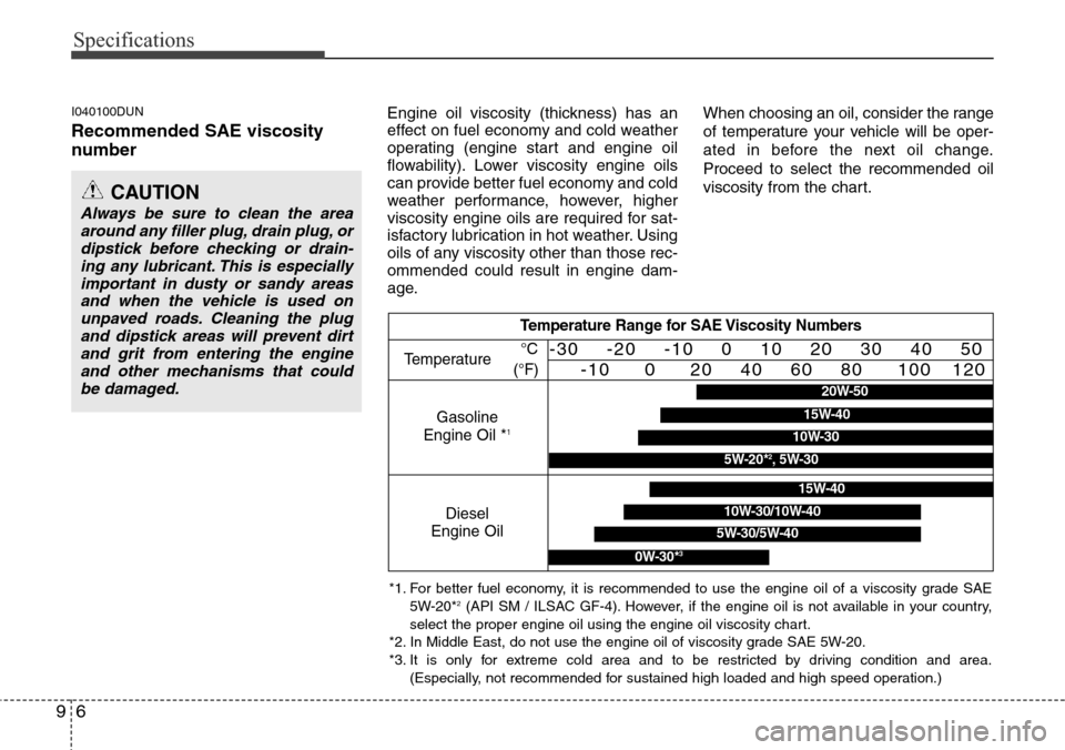
Proceed to select the recommended oil
viscosity from the chart.
CAUTION
Always be sure to clean the area
around any filler plug, drain plug, or
dipstick before checking or drain-
ing any lubricant. This is especially
important in dusty or sandy areas
and when the vehicle is used on
unpaved roads. Cleaning the plug
and dipstick areas will prevent dirt
and grit from entering the engine
and other mechanisms that could
be damaged.
Temperature Range for SAE Viscosity Numbers
Temperature
Gasoline
Engine Oil *
1
°C
(°F)-30 -20 -10 0 10 20 30 40 50
-10 0 20 40 60 80 100 120
Diesel
Engine Oil
5W-30/5W-40
15W-40
10W-30/10W-40
0W-30*3
*1. For better fuel economy, it is recommended to use the engine oil of a viscosity grade SAE
5W-20*2(API SM / ILSAC GF-4). However, if the engine oil is not available in your country,
select the proper engine oil using the engine oil viscosity chart.
*2. In Middle East, do not use the engine oil of viscosity grade SAE 5W-20.
*3. It is only for extreme cold area and to be restricted by driving condition and area.
(Especially, not recommended for sustained high loaded and high speed operation.)
20W-50
10W-30
15W-40
5W-20*2, 5W-30