Page 364 of 416
Although this seems like a simple
procedure, you should take several
precautions.To jump start your vehicle:
The numbers in the illustration show
you the order to connect the jumper
cables.
You cannot start your vehicle by
pushing or pulling it. Open the hood, and check the
physical condition of the 12 volt
battery.
Turn of f all the electrical
accessories: climate control, audio
system, lights, etc. Put the
transmission in Park, and set the
parking brake.
1. 2.
Jump Start ing
360 BOOSTER
BATTERY
A battery can explode if you do
not follow the correct procedure,
seriously injuring anyonenearby.
Keep all sparks, open flames,
and smoking materials away
from the battery.
If a battery sits in extreme cold, the
electrolyte inside can f reeze.
Attempting to jump start with a f rozen
battery can cause it to rupture.
Page 366 of 416

position. It will s")
If your vehicle’s 12 volt battery is
disconnected or goes dead, the IMA
battery level gauge reading will not
be correct the next time you turn the
ignition switch to the ON (II)
position. It will show less than the
actual level temporarily. It will show
the correct level af ter you drive f or
at least 30 minutes.The high temperature indicator
should be of f under most conditions.
If the engine coolant temperature
gets higher than normal, the
indicator will blink. If it stays on, you
should determine the reason (hot
day, driving up a steep hill, etc.).
You will also see a ‘‘WATER TEMP
HOT’’ message on the multi-
inf ormation display (see page ).If the vehicle overheats, you should
take immediate action. The only
indication may be the high
temperature indicator blinking or
remaining on. Or you may see steam
or spray coming f rom under thehood.
67
If the Engine Overheats
Jump St art ing, If t he Engine Overheat s
362 Driving with the high temperature
indicator on can cause serious damage
to your engine.
Page 368 of 416

Using gloves or a large heavy
cloth, turn the radiator cap
counterclockwise, without pushing
down, to the f irst stop. Af ter the
pressure releases, push down on
the cap, and turn it until it comes
off.If the temperature stays normal,
check the coolant level in the
radiator reserve tank. If it has
gone down, add coolant to the
MAX mark. Put the cap back on
tightly.
Start the engine, and set the
temperature to maximum heat
(climate control to AUTO at
‘‘ ’’). Add coolant to the
radiator up to the base of the f iller
neck. If you do not have the
proper coolant mixture available,
you can add plain water.
Remember to have the cooling
system drained and ref illed with
the proper mixture as soon as you
can.
Put the radiator cap back on
tightly. Run the engine, and check
the high temperature indicator. If
it begins to blink or comes on
again, the engine needs repair
(see on page
).
8. 9.
10. 11.
376
If theEngineOverheats
Emergency T owing
364 Removing the radiator cap
while the engine is hot can
cause the coolant to spray out,
seriously scalding you.
Always let the engine and
radiator cool down before
removing the radiator cap.
Page 370 of 416
�µ�µ
If the charging system
indicator comes on brightly
when the engine is running, the 12
volt battery is not being charged.
Go to a service station or garage
where you can get technical
assistance.
Immediately turn of f all electrical
accessories. Try not to use other
electrically operated controls such as
the power windows. Keep the engine
running; starting the engine will
discharge the battery rapidly.
You will also see a ‘‘CHECK
CHARGING SYSTEM’’ message on
the multi-information display (see
page ).
This indicator may blink af ter you
start the vehicle in the morning
when the temperature is below
20°F ( 30°C). It will stop
blinking when the IMA battery
warms up.
89
12 Volt Battery Charging System Indicator
366
Page 378 of 416
�µ �µ �µ
�µ �µ
�Î
�Î
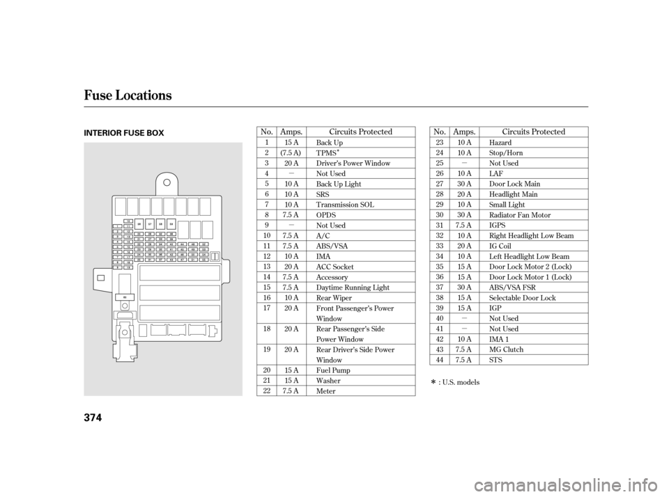
No.
No. Amps.
Amps. Circuits Protected
Circuits Protected
1 23456789
1011121314151617 181920 2122 23242526272829303132333435363738394041424344
10 A
10 A
10 A
30 A
20 A
10 A
30 A
7.5 A 10 A
20 A
10 A
15 A
15 A
30 A
15 A
15 A
10 A
7.5 A
7.5 A
15 A
(7.5 A) 20 A
10 A
10 A
10 A
7.5 A
7.5 A
7.5 A 10 A
20 A
7.5 A
7.5 A 10 A
20 A
20 A
20 A
15 A
15 A
7.5 A Hazard
Stop/Horn
Not UsedLAF
Door Lock Main
Headlight Main
Small Light
Radiator Fan Motor
IGPS
Right Headlight Low Beam
IG Coil
Left Headlight Low Beam
Door Lock Motor 2 (Lock)
Door Lock Motor 1 (Lock)
ABS/VSA FSR
Selectable Door Lock
IGP
Not Used
Not Used
IMA 1
MG Clutch
STS
Back Up
TPMS
Driver’s Power Window
Not Used
Back Up Light
SRS
T ransmission SOLOPDS
Not Used
A/C
ABS/VSA
IMA
ACC Socket
Accessory
Daytime Running Light
Rear Wiper
Front Passenger’s Power
Window
Rear Passenger’s Side
Power Window
Rear Driver’s Side Power
Window
Fuel Pump
Washer
Meter
: U.S. models
Fuse Locations
374
INTERIOR FUSE BOX
Page 379 of 416
�µ �µ �µ
�Î �Î�Î �Î�Î
�Π��ΠNo. Circuits Protected
No.
Amps.
Amps.
No. Amps. Circuits Protected
Circuits Protected
1 2Ignition Coil (EX)
Ignition Coil (IN)
454647484950515253545556575859 60
15 A
15 A
7.5 A
30 A
10 A
15 A
15 A
10 A
15 A
10 A
10 A
30 A
30 A
30 A
30 A
40 A
50 A 1 23100 A
60 A
20 A Battery, Main, ACGEPS
Horn, Stop, Hazard
Hatch Lock
Not Used
Condenser Fan Motor
Left Headlight High Beam
Door Lock Motor 2 (Unlock)
Door Lock Motor 1 (Unlock)
Right Headlight High Beam
DBW
IMA 2
Not Used
Heated Mirror
Front Wiper
Blower Motor
ABS/VSA Motor
Rear Defogger
Rear Defogger
Not Used
IG Main
1:2:3: Insight model and U.S. LX model
Canadian models
EX models 2, 3
1
2, 3
Fuse Locations
T aking Care of t he Unexpect ed
375
UNDER-HOOD FUSE BOXES
On the battery Next to the battery
Page 385 of 416
The engine number is stamped into
the engine block.
The transmission number is on a
label on top of the transmission.
The IMA Motor Number is stamped
on the motor housing.
Identif ication Numbers
T echnical Inf ormat ion
381
ENGINE NUMBER
TRANSMISSION NUMBER IMA MOTOR NUMBER
Page 388 of 416

Quality grades can be f ound where
applicable on the tire sidewall
between tread shoulder and
maximum section width. For
example:
All passenger car tires must conf orm
to Federal Saf ety Requirements in
addition to these grades.The traction grades, f rom highest to
lowest, are AA, A, B, and C. Those
grades represent the tire’s ability to
stop on wet pavement as measured
under controlled conditions on
specif ied government test surf aces
of asphalt and concrete. A tire
marked C may have poor traction
perf ormance.
Warning: The traction grade
assignedtothistireisbasedon
straight-ahead braking traction tests,
and does not include acceleration,
cornering, hydroplaning, or peak
traction characteristics.
The tires on your vehicle meet all
U.S. Federal Saf ety Requirements.
All tires are also graded f or
treadwear, traction, and temperature
perf ormance according to
Department of Transportation
(DOT) standards. The f ollowing
explains these gradings.
The treadwear grade is a compara-
tive rating based on the wear rate of
the tire when tested under controlled
conditions on a specif ied government
test course. For example, a tire
graded 150 would wear one and one-
half (1 1/2) times as well on the
government course as a tire graded
100. The relative perf ormance of
tires depends upon the actual condi-
tions of their use, however, and may
depart signif icantly f rom the norm
due to variations in driving habits,
service practices and dif f erences in
road characteristics and climate.
Unif orm T ire Quality Grading
T readwear 200
Traction AA
Temperature A T readwear T raction
DOT T ire Qualit y Grading (U.S. Vehicles)
384