Page 66 of 400

If you turn the steering wheel to the
f ull lef t or right position repeatedly
while stopping or driving at very low
speed, you may f eel slightly harder
steering due to overheating of the
steering gearbox.
Continuously driving under those
conditions could damage the power
steering system.This indicator comes on f or a f ew
seconds when you turn the ignition
switch to the ON (II) position. It
remindsyouthatitistimetotake
your vehicle in f or scheduled
maintenance. The maintenance main
items and sub items will be displayed
in the information display. See page
f or more inf ormation on the
Maintenance Minder .
This indicator goes of f when your
dealer resets it after completing the
required maintenance service.
This indicator normally comes on
when you turn the ignition switch to
the ON (II) position and goes of f
af ter the engine starts. If it comes on
at any other time, there is a problem
in the electric power steering system.
If this happens, stop the vehicle in a
saf e place, and turn of f the engine.
Reset the system by restarting the
engine. The indicator will not turn
of f immediately. If it does not go of f
after driving a short distance, or
comes back on again while driving,
take the vehicle to your dealer to
have it checked. With the indicator
on, the EPS may be of f , making the
vehicle harder to steer.
291
Instrument Panel Indicators
Electric Power Steering
(EPS) Indicator
Maintenance Minder
Indicator
Si and Canadian DX-G with manual
t ransmission models
62
TM
Main Menu
Page 67 of 400

position. If it comes on while driving,
it indicates that one or more of your
vehicle’s tires a")
This indicator normally comes on f or
a f ew seconds when you turn the
ignition switch to the ON (II)
position. If it comes on while driving,
it indicates that one or more of your
vehicle’s tires are signif icantly low
on pressure.
If this happens, pull to the side of the
road when it is saf e, check which tire
has lost pressure, and determine the
cause. If it is because of a f lat tire,
replace the flat tire with the compact
spare (see page ), and have the
f lat tire repaired as soon as possible.
If two or more tires are underinf lated,
call a prof essional towing service
(see page ). For more
inf ormation, see page .If this indicator comes on and stays
on at any other time, or if it does not
come on when you turn the ignition
switch to the ON (II) position, there
is a problem with the TPMS. With
this indicator on, the low tire
pressure indicator will not come on
when a tire loses pressure. Take the
vehicle to your dealer to have the
system checked. For more
inf ormation, see page .
This indicator normally comes on f or
a f ew seconds when you turn the
ignition switch to the ON (II)
position.
To protect the engine f rom damage,
never drive with the tachometer in
its red zone.
This indicator shows you when the
engine speed is near the tachometer’s
red zone. When the engine speed
gets to near the red zone, the
indicator blinks. If you exceed the
maximum speed f or the gear you are
in, the indicator stays on, and you
may f eel the engine cut in and out
due to the engine speed limiter (see
page ).
339
358 284 273
285
U.S. models only U.S. models only
Tire Pressure Monitoring
System (T PMS) Indicator
Low Tire Pressure
Indicator Rev L imit Indicator
Instrument Panel Indicators
Inst rument s and Cont rols
Si model only
63
REV LIMIT INDICATOR
Main Menu
Page 71 of 400
�Î
�Î
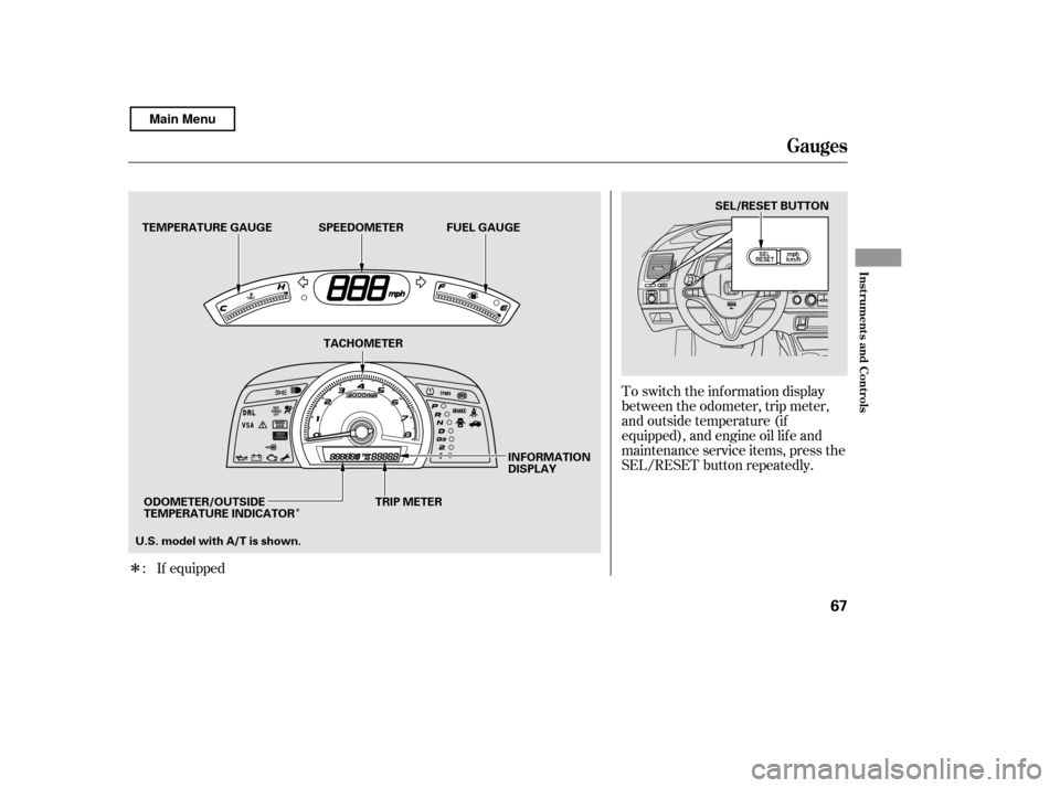
If equippedTo switch the information display
between the odometer, trip meter,
and outside temperature (if
equipped), and engine oil lif e and
maintenance service items, press the
SEL/RESET button repeatedly.
:
Gauges
Inst rument s and Cont rols
67
INFORMATION
DISPLAY
TACHOMETER
TEMPERATURE GAUGE
SEL/RESET BUTTON
TRIP METER
ODOMETER/OUTSIDE
TEMPERATURE INDICATOR
U.S. model with A/T is shown. SPEEDOMETER
FUEL GAUGE
Main Menu
Page 73 of 400
 or Celsius (Canadian
models). To see the outside
temperature, press and release the
SEL/RE")
�¶�¶�µ
�µ�µ�µ�µ
�µ�µ�µ
This indicator displays the outside
temperature in Fahrenheit (U.S.
models) or Celsius (Canadian
models). To see the outside
temperature, press and release the
SEL/RESET button until the
temperature is shown on the
inf ormation display.
The temperature sensor is in the
f ront bumper. Theref ore, the
temperature reading can be af f ected
by heat ref lection f rom the road
surf ace, engine heat, and the
exhaust f rom surrounding traf f ic.
This can cause an incorrect
temperature reading when your
speed is under 19 mph (30 km/h).
The sensor delays the display update
until it reaches the correct outside
temperature. This may take several
minutes. In certain weather conditions,
temperature readings near f reezing
(32°F, 0°C) could mean that ice is
f orming on the road surf ace.
If the outside temperature is
incorrectly displayed, you can adjust
it up to 5°F in U.S. models ( 3°C
in Canadian models) warmer or
cooler.
When it reaches the desired value,
release the SEL/RESET button. You
should see the new outside
temperature displayed.
Select the outside temperature
display, then press and hold the
SEL/RESET button f or 10 seconds.
The f ollowing sequence will appear
for1secondeach:0,1,2,3,4,5, 5,
4, 3, 2, 1, 0 (U.S.) or 0, 1, 2,
3, 3, 2, 1, 0 (Canada). The temperature must be
stabilized bef ore doing this
procedure.
If equipped
Outside Temperature Indicator
Gauges
Inst rument s and Cont rols
69
NOTE:
Main Menu
Page 74 of 400

This shows how much f uel you have.
It may show slightly more or less
than the actual amount.This shows the temperature of the
engine’s coolant. During normal
operation, the reading should rise to
about the middle of the gauge. In
severe driving conditions, such as
very hot weather or a long period of
uphill driving, the reading may rise
intotheupperhalfofthegauge.Ifit
reaches the red (Hot) mark, pull
safely to the side of the road. See
page f or instructions and
precautions on checking the engine
cooling system.Your vehicle’s onboard diagnostic
system will detect a loose or missing
f uel f ill cap as an evaporative system
leak. The f irst time a leak is detected
a ‘‘CHECK FUEL CAP’’ message
appears on the information display.
Turn the engine of f , and conf irm the
f uel f ill cap is installed. If it is, loosen
it, then retighten it until it clicks at
least once. The message should go
off after several days of normal
driving once you tighten or replace
the f uel f ill cap. To scroll to another
display, press the SEL/RESET
button. The ‘‘CHECK FUEL CAP’’
message will appear each time you
restart the engine until the system
turns the message of f .
347
Fuel Gauge T emperature Gauge Check Fuel Cap Message
Gauges
70
Avoid driving with an extremely low
f uel level. Running out of f uel could
cause the engine to misf ire, damaging
the catalytic converter.
Main Menu
Page 75 of 400
The inf ormation display in the
instrument panel shows you the
engine oil lif e and maintenance
service items when the ignition
switch is in the ON (II) position. This
inf ormation helps to keep you aware
of the periodic maintenance your
vehicle needs f or continued trouble-
f ree driving. Ref er to page f or
more inf ormation.
If the system still detects a leak in
your vehicle’s evaporative emissions
system, the malf unction indicator
lamp (MIL) comes on. If the f uel f ill
cap was not already tightened, turn
the engine of f , and check or
retighten the f uel f ill cap until it
clicks at least once. The MIL should
go off after several days of normal
driving once the cap is tightened or
replaced. If the MIL does not go of f ,
have your vehicle inspected by a
dealer. For more inf ormation, see
page .
350 291
Maintenance Minder
Gauges
Inst rument s and Cont rols
71
TM
Main Menu
Page 84 of 400

If the system repeatedly does not
recognize the coding of your key,
contact your dealer.
Do not attempt to alter this system
or add other devices to it. Electrical
problems could result that may make
your vehicle inoperable.
If you have lost your key and cannot
start your engine, contact your
dealer.
When you turn the ignition switch to
the ON (II) position, the immobilizer
system indicator should come on
brief ly, then go of f . If the indicator
starts to blink, it means the system
does not recognize the coding of the
key. Turn the ignition switch to the
LOCK (0) position, remove the key,
reinsert it, and turn the ignition
switch to the ON (II) position again.
The immobilizer system protects
your vehicle f rom thef t. If an
improperly coded key (or other
device) is used, the engine’s f uel
system is disabled.
These keys contain electronic
circuits that are activated by the
immobilizer system. They will not
work to start the engine if the
circuits are damaged.
Protect the keys f rom direct
sunlight, high temperature, and
high humidity.
Donotdropthekeysorsetheavy
objects on them.
The keys do not contain batteries.
Do not try to take them apart. Keep the keys away f rom liquids.
If they get wet, dry them
immediately with a sof t cloth.
The valet key does not contain a
battery. Do not try to take it apart. The system may not recognize your key’s coding if another immobilizer
key or other metal object (i.e. key
chain) is near the ignition switch
when you insert the key.
On DX model (except Canadian DX-G)
Immobilizer System
Keys and Locks, Immobilizer System
80
Always take the ignition key with you
whenever you leave the vehicle alone.
Main Menu
Page 85 of 400

�µ
�µ
�µ
�µ If the f ront wheels are turned, the
anti-thef t lock may make it dif f icult
to turn the key. Firmly turn the
steering wheel to the lef t or right as
you turn the key.
You can
operate the audio system and the
accessory power sockets in this
position.
This is the normal key
position when driving. Several of the
indicators on the instrument panel
come on as a test when you turn the
ignition switch f rom the
ACCESSORY (I) to the ON (II)
position.
Use this position
only to start the engine. The switch
returns to the ON (II) position when
you let go of the key.
You can insert or
remove the key only in this position.
To turn the key, push it in slightly. If
your vehicle has an automatic
transmission, the shif t lever must
also be in park.
The ignition switch has f our
positions: LOCK (0), ACCESSORY
(I), ON (II), and START (III).
As required by the FCC:
This device complies with Part 15 of theFCC rules. Operation is subject to the
f ollowing two conditions: (1) This devicemay not cause harmf ul interf erence, and (2) this device must accept any
interf erence received, includinginterf erence that may cause undesiredoperation.
Changes or modif ications not expresslyapproved by the party responsible f or
compliance could void the user’sauthority to operate the equipment.
This device complies with IndustryCanada Standard RSS-210.Operation is subject to the f ollowing two
conditions: (1) this device may not causeinterf erence, and (2) this device mustaccept any interf erence that may cause
undesired operation of the device.
CONT INUED
A CCESSORY (I)
ON (II)
ST A RT (III)
LOCK (0)
Ignition Switch
Immobilizer Syst em, Ignit ion Switch
Inst rument s and Cont rols
81
Main Menu
 position. This
inf ormation helps to keep you")