2011 FORD KUGA Oil cooler
[x] Cancel search: Oil coolerPage 1518 of 2057
Engine
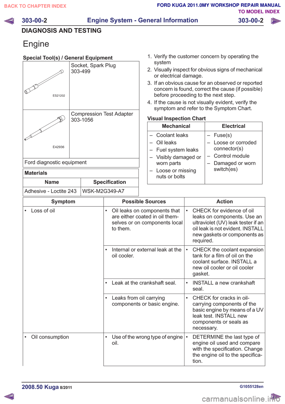
Special Tool(s) / General EquipmentSocket, Spark Plug
303-499
ES21202
Compression Test Adapter
303-1056
E42936
Ford diagnostic equipment
Materials
Specification
Name
WSK-M2G349-A7
Adhesive - Loctite 243 1. Verify the customer concern by operating the
system
2. Visually inspect for obvious signs of mechanical or electrical damage.
3. If an obvious cause for an observed or reported concern is found, correct the cause (if possible)
before proceeding to the next step.
4. If the cause is not visually evident, verify the symptom and refer to the Symptom Chart.
Visual Inspection Chart
Electrical
Mechanical
– Fuse(s)
– Loose or corrodedconnector(s)
– Control module
– Damaged or worn switch(es)
– Coolant leaks
– Oil leaks
– Fuel system leaks
– Visibly damaged or
worn parts
– Loose or missing nuts or bolts
Action
Possible Sources
Symptom
• CHECK for evidence of oilleaks on components. Use an
ultraviolet (UV) leak tester if an
oil leak is not evident. INSTALL
new gaskets or components as
required.
• Oil leaks on components that
are either coated in oil them-
selves or on components local
to them.
• Loss of oil
• CHECK the coolant expansiontank for a film of oil on the
coolant surface. INSTALL a
new oil cooler or oil cooler
gasket.
• Internal or external leak at the
oil cooler.
• INSTALL a new crankshaftseal.
• Leak at the crankshaft seal.
• CHECK for cracks in oil-carrying components of the
basic engine by means of a UV
leak test. INSTALL new
components or seals as
necessary.
• Leaks from oil carrying
components or basic engine.
• DETERMINE the last type ofengine oil used and compare
with the specification. Change
the engine oil to the specifica-
tion.
• Use of the wrong type of engine
oil.
• Oil consumption
G1055128en2008.50 Kuga8/2011
303-00-
2
Engine System - General Information
303-00- 2
DIAGNOSIS AND TESTING
TO MODEL INDEX
BACK TO CHAPTER INDEX
FORD KUGA 2011.0MY WORKSHOP REPAIR MANUAL
Page 1520 of 2057
Action
Possible Sources
Symptom
• Check the cooling systemcomponents. Engine - 2.5L
Duratec-ST (VI5) -
REFER to: Engine Cooling
(303-03 Engine Cooling,
Diagnosis and Testing).
Engine - 2.0L Duratorq-TDCi
(DW) Diesel -
REFER to: Engine Cooling
(303-03 Engine Cooling,
Diagnosis and Testing).
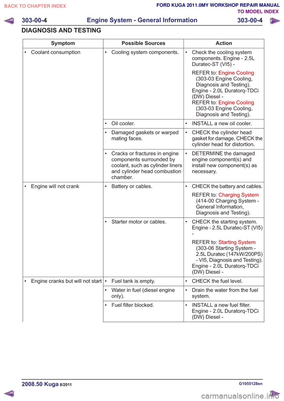
• Cooling system components.
• Coolant consumption
• INSTALL a new oil cooler.
• Oil cooler.
• CHECK the cylinder headgasket for damage. CHECK the
cylinder head for distortion.
• Damaged gaskets or warped
mating faces.
• DETERMINE the damagedengine component(s) and
install new component(s) as
necessary.
• Cracks or fractures in engine
components surrounded by
coolant, such as cylinder liners
and cylinder head combustion
chamber.
• CHECK the battery and cables.REFER to: Charging System
(414-00 Charging System -
General Information,
Diagnosis and Testing).
• Battery or cables.
• Engine will not crank
• CHECK the starting system.Engine - 2.5L Duratec-ST (VI5)
-
REFER to: Starting System
(303-06 Starting System -
2.5L Duratec (147kW/200PS)
- VI5, Diagnosis and Testing).
Engine - 2.0L Duratorq-TDCi
(DW) Diesel -
• Starter motor or cables.
• CHECK the fuel level.
• Fuel tank is empty.
• Engine cranks but will not start
• Drain the water from the fuelsystem.
• Water in fuel (diesel engine
only).
• INSTALL a new fuel filter.Engine - 2.0L Duratorq-TDCi
(DW) Diesel -
• Fuel filter blocked.
G1055128en2008.50 Kuga8/2011
303-00-
4
Engine System - General Information
303-00- 4
DIAGNOSIS AND TESTING
TO MODEL INDEX
BACK TO CHAPTER INDEX
FORD KUGA 2011.0MY WORKSHOP REPAIR MANUAL
Page 1534 of 2057
SECTION 303-01 Engine— 2.5L Duratec (147kW/200PS) - VI5
VEHICLE APPLICATION:2008.50 Kuga
PA G E
CONTENTS
SPECIFICATIONS
303-01-3
Specifications ........................................................................\
..............................................
303-01-3
Engine Data ........................................................................\
............................................
303-01-3
Engine Oil ........................................................................\
...............................................
303-01-3
Engine Oil Capacity ........................................................................\
................................
303-01-3
Oil Pressure ........................................................................\
............................................
303-01-4
Valve Clearance ........................................................................\
......................................
303-01-4
Crankshaft Main Bearing Selection ........................................................................\
........
DESCRIPTION AND OPERATION 303-01-6
Engine (Component Location) ........................................................................\
....................
303-01-9
Engine (Overview) ........................................................................\
......................................
303-01-9
General ........................................................................\
.......................................................
303-01-10
Cylinder head ........................................................................\
.............................................
303-01-14
Cylinder block ........................................................................\
.............................................
303-01-16
Engine (System Operation and Component Description) ...................................................
303-01-16
System Operation ........................................................................\
.......................................
303-01-17
Variable camshaft timing ........................................................................\
.........................
GENERAL PROCEDURES 303-01-19
Valve Clearance Adjustment ........................................................................\
.......................
REMOVAL AND INSTALLATION 303-01-20
(21 183 0)
Intake Manifold ........................................................................\
.......................
303-01-22
(21 467 0)
Crankshaft Front Seal ........................................................................\
.............
303-01-23
(21 238 0)
Valve Stem Seals ........................................................................\
...................
303-01-25
(21 304 0)
Timing Belt ........................................................................\
..............................
303-01-31
(21 284 0)
Camshafts ........................................................................\
..............................
303-01-36
(21 288 0)
Camshaft Seal ........................................................................\
........................
303-01-45
(21 154 0)
Oil Pan ........................................................................\
....................................
303-01-48
(21 714 0)
Oil Pump ........................................................................\
.................................
303-01-49
(21 187 0)
Exhaust Manifold ........................................................................\
....................
303-01-50
(21 163 0)
Cylinder Head ........................................................................\
.........................
303-01-56
(21 468 4)
Crankshaft Rear Seal ........................................................................\
.............
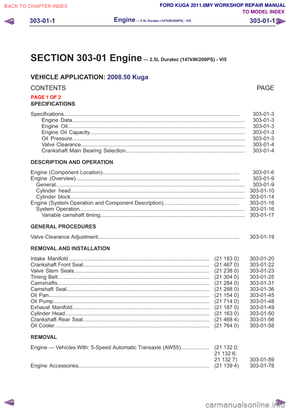
303-01-58
(21 764 0)
Oil Cooler ........................................................................\
................................
REMOVAL
303-01-59
(21
132 0;
21 132 6;
21 132 7)
Engine — Vehicles With: 5-Speed Automatic Transaxle (AW55)
...................
303-01-78
(21 139 4)
Engine Accessories ........................................................................\
................
303-01-1
Engine— 2.5L Duratec (147kW/200PS) - VI5303-01-
1
.
TO MODEL INDEX
BACK TO CHAPTER INDEX
PAGE 1 OF 2 FORD KUGA 2011.0MY WORKSHOP REPAIR MANUAL
Page 1591 of 2057
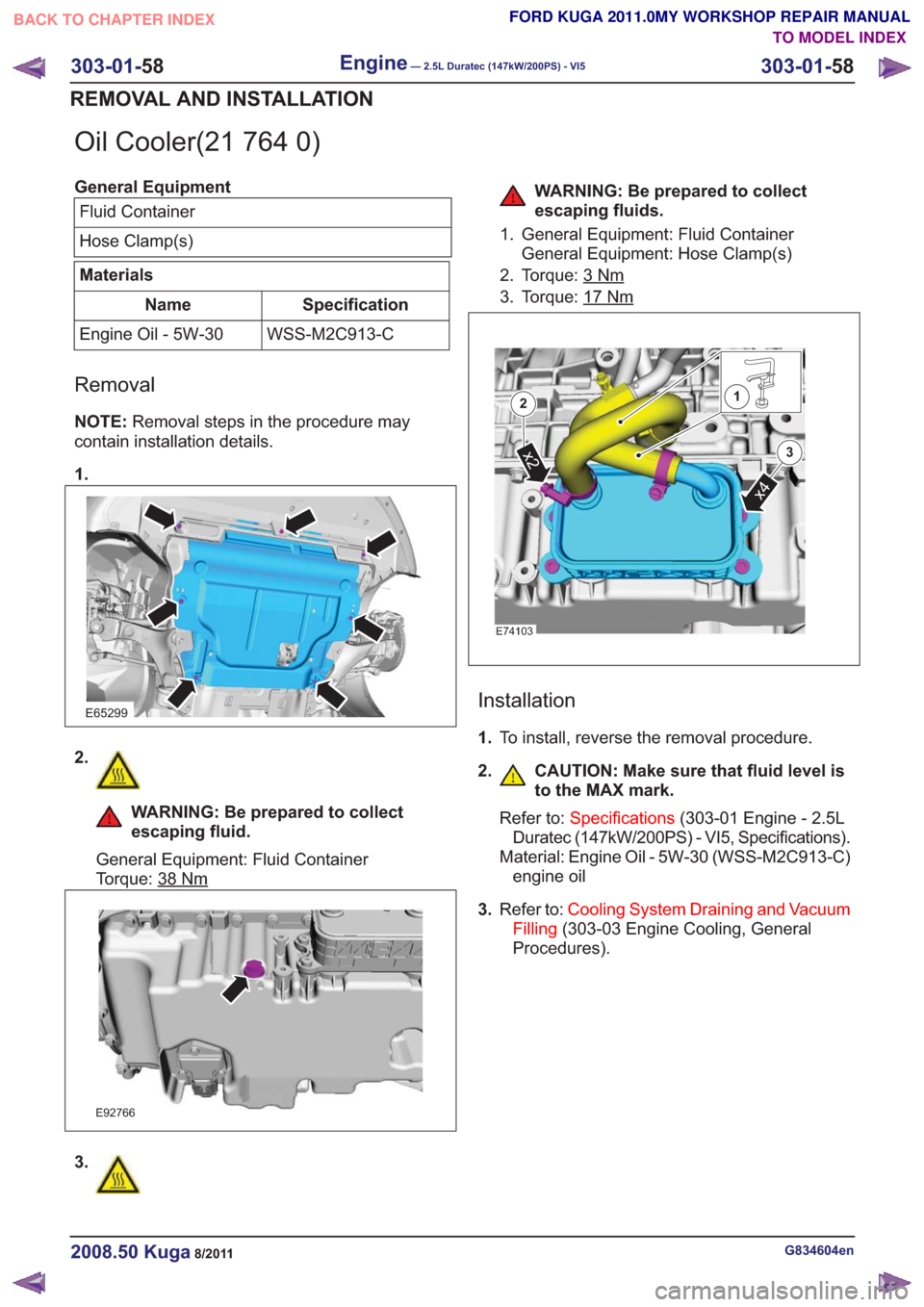
Oil Cooler(21 764 0)
General EquipmentFluid Container
Hose Clamp(s)
Materials
Specification
Name
WSS-M2C913-C
Engine Oil - 5W-30
Removal
NOTE: Removal steps in the procedure may
contain installation details.
1.
E65299
2.
WARNING: Be prepared to collect
escaping fluid.
General Equipment: Fluid Container
Torque: 38
Nm
E92766
3.
WARNING: Be prepared to collect
escaping fluids.
1. General Equipment: Fluid Container General Equipment: Hose Clamp(s)
2. Torque: 3
Nm
3. Torque: 17Nm
E74103
x4
x2
2
3
1
Installation
1. To install, reverse the removal procedure.
2. CAUTION: Make sure that fluid level is to the MAX mark.
Refer to: Specifications (303-01 Engine - 2.5L
Duratec (147kW/200PS) - VI5, Specifications).
Material: Engine Oil - 5W-30 (WSS-M2C913-C) engine oil
3. Refer to: Cooling System Draining and Vacuum
Filling (303-03 Engine Cooling, General
Procedures).
G834604en2008.50 Kuga8/2011
303-01- 58
Engine— 2.5L Duratec (147kW/200PS) - VI5303-01-
58
REMOVAL AND INSTALLATION
TO MODEL INDEX
BACK TO CHAPTER INDEX
FORD KUGA 2011.0MY WORKSHOP REPAIR MANUAL
Page 1673 of 2057
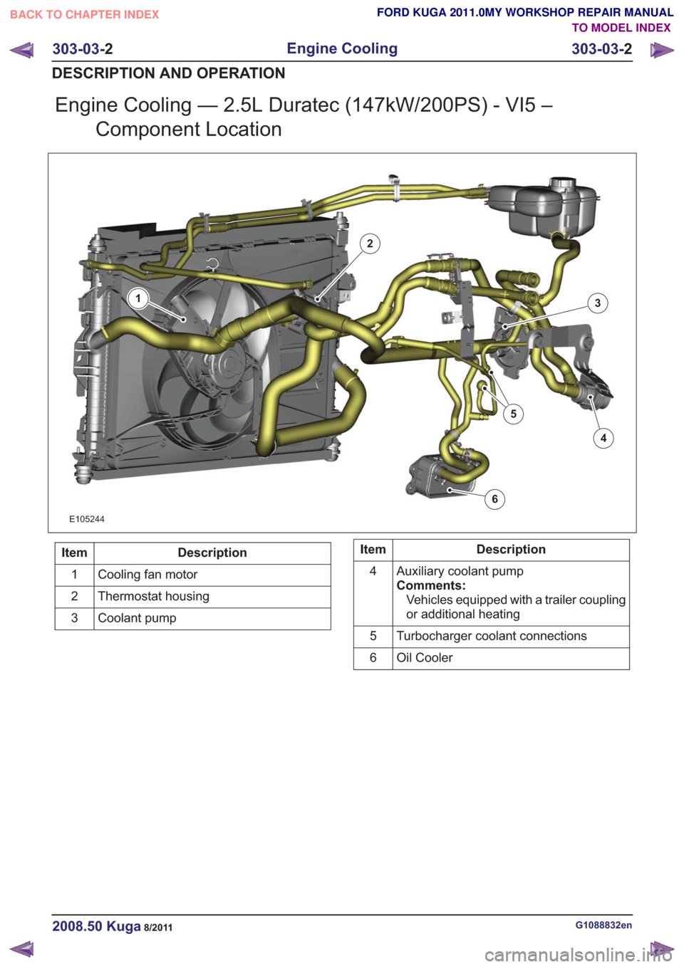
Engine Cooling — 2.5L Duratec (147kW/200PS) - VI5 –Component Location
E105244
1
2
3
4
5
6
Description
Item
Cooling fan motor
1
Thermostat housing
2
Coolant pump
3Description
Item
Auxiliary coolant pump
Comments:Vehicles equipped with a trailer coupling
or additional heating
4
Turbocharger coolant connections
5
Oil Cooler
6
G1088832en2008.50 Kuga8/2011
303-03- 2
Engine Cooling
303-03- 2
DESCRIPTION AND OPERATION
TO MODEL INDEX
BACK TO CHAPTER INDEX
FORD KUGA 2011.0MY WORKSHOP REPAIR MANUAL
Page 1725 of 2057
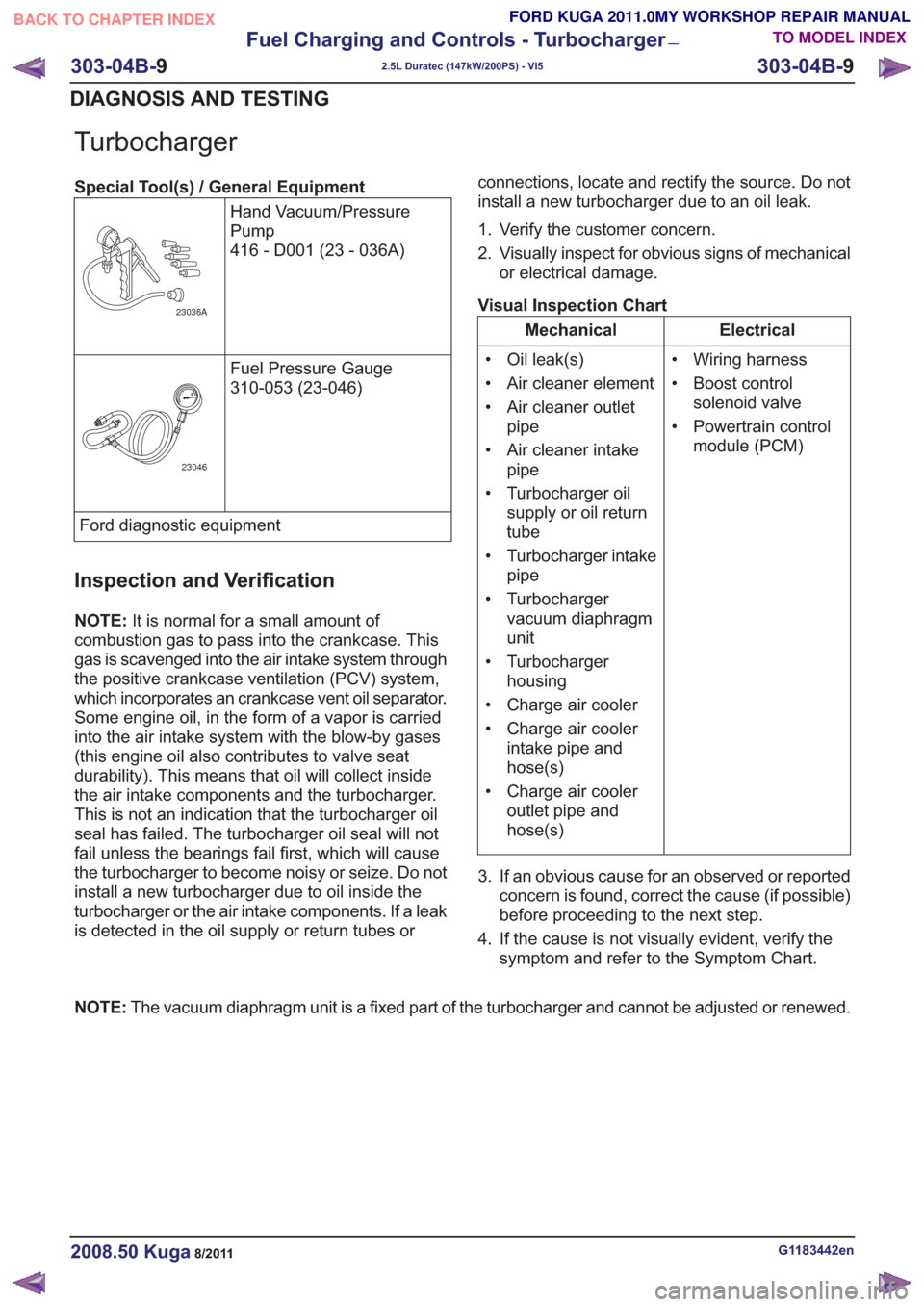
Turbocharger
Special Tool(s) / General EquipmentHand Vacuum/Pressure
Pump
416 - D001 (23 - 036A)
23036A
Fuel Pressure Gauge
310-053 (23-046)
23046
Ford diagnostic equipment
Inspection and Verification
NOTE:It is normal for a small amount of
combustion gas to pass into the crankcase. This
gas is scavenged into the air intake system through
the positive crankcase ventilation (PCV) system,
which incorporates an crankcase vent oil separator.
Some engine oil, in the form of a vapor is carried
into the air intake system with the blow-by gases
(this engine oil also contributes to valve seat
durability). This means that oil will collect inside
the air intake components and the turbocharger.
This is not an indication that the turbocharger oil
seal has failed. The turbocharger oil seal will not
fail unless the bearings fail first, which will cause
the turbocharger to become noisy or seize. Do not
install a new turbocharger due to oil inside the
turbocharger or the air intake components. If a leak
is detected in the oil supply or return tubes or connections, locate and rectify the source. Do not
install a new turbocharger due to an oil leak.
1. Verify the customer concern.
2. Visually inspect for obvious signs of mechanical
or electrical damage.
Visual Inspection Chart
Electrical
Mechanical
• Wiring harness
• Boost controlsolenoid valve
• Powertrain control module (PCM)
• Oil leak(s)
• Air cleaner element
• Air cleaner outlet
pipe
• Air cleaner intake pipe
• Turbocharger oil supply or oil return
tube
• Turbocharger intake pipe
• Turbocharger vacuum diaphragm
unit
• Turbocharger housing
• Charge air cooler
• Charge air cooler intake pipe and
hose(s)
• Charge air cooler outlet pipe and
hose(s)
3. If an obvious cause for an observed or reported concern is found, correct the cause (if possible)
before proceeding to the next step.
4. If the cause is not visually evident, verify the symptom and refer to the Symptom Chart.
NOTE: The vacuum diaphragm unit is a fixed part of the turbocharger and cannot be adjusted or renewed.
G1183442en2008.50 Kuga8/2011
303-04B- 9
Fuel Charging and Controls - Turbocharger
—
2.5L Duratec (147kW/200PS) - VI5
303-04B- 9
DIAGNOSIS AND TESTING
TO MODEL INDEX
BACK TO CHAPTER INDEX
FORD KUGA 2011.0MY WORKSHOP REPAIR MANUAL
Page 1726 of 2057
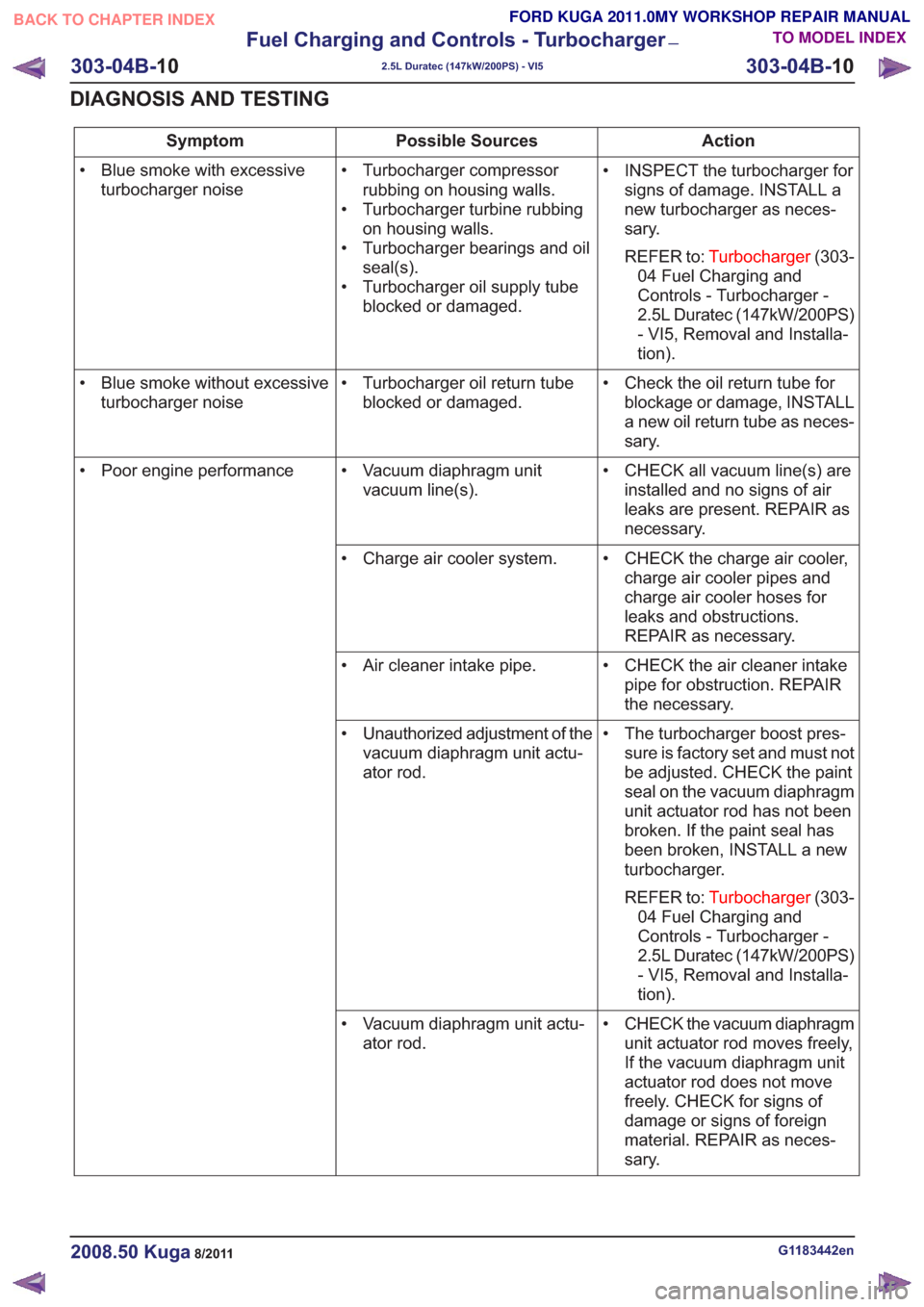
Action
Possible Sources
Symptom
• INSPECT the turbocharger forsigns of damage. INSTALL a
new turbocharger as neces-
sary.
REFER to: Turbocharger (303-
04 Fuel Charging and
Controls - Turbocharger -
2.5L Duratec (147kW/200PS)
- VI5, Removal and Installa-
tion).
• Turbocharger compressor
rubbing on housing walls.
• Turbocharger turbine rubbing on housing walls.
• Turbocharger bearings and oil seal(s).
• Turbocharger oil supply tube blocked or damaged.
• Blue smoke with excessive
turbocharger noise
• Check the oil return tube forblockage or damage, INSTALL
a new oil return tube as neces-
sary.
• Turbocharger oil return tube
blocked or damaged.
• Blue smoke without excessive
turbocharger noise
• CHECK all vacuum line(s) areinstalled and no signs of air
leaks are present. REPAIR as
necessary.
• Vacuum diaphragm unit
vacuum line(s).
• Poor engine performance
• CHECK the charge air cooler,charge air cooler pipes and
charge air cooler hoses for
leaks and obstructions.
REPAIR as necessary.
• Charge air cooler system.
• CHECK the air cleaner intakepipe for obstruction. REPAIR
the necessary.
• Air cleaner intake pipe.
• The turbocharger boost pres-sure is factory set and must not
be adjusted. CHECK the paint
seal on the vacuum diaphragm
unit actuator rod has not been
broken. If the paint seal has
been broken, INSTALL a new
turbocharger.
REFER to: Turbocharger (303-
04 Fuel Charging and
Controls - Turbocharger -
2.5L Duratec (147kW/200PS)
- VI5, Removal and Installa-
tion).
• Unauthorized adjustment of the
vacuum diaphragm unit actu-
ator rod.
• CHECK the vacuum diaphragmunit actuator rod moves freely,
If the vacuum diaphragm unit
actuator rod does not move
freely. CHECK for signs of
damage or signs of foreign
material. REPAIR as neces-
sary.
• Vacuum diaphragm unit actu-
ator rod.
G1183442en2008.50 Kuga8/2011
303-04B- 10
Fuel Charging and Controls - Turbocharger
—
2.5L Duratec (147kW/200PS) - VI5
303-04B- 10
DIAGNOSIS AND TESTING
TO MODEL INDEX
BACK TO CHAPTER INDEX
FORD KUGA 2011.0MY WORKSHOP REPAIR MANUAL
Page 1768 of 2057
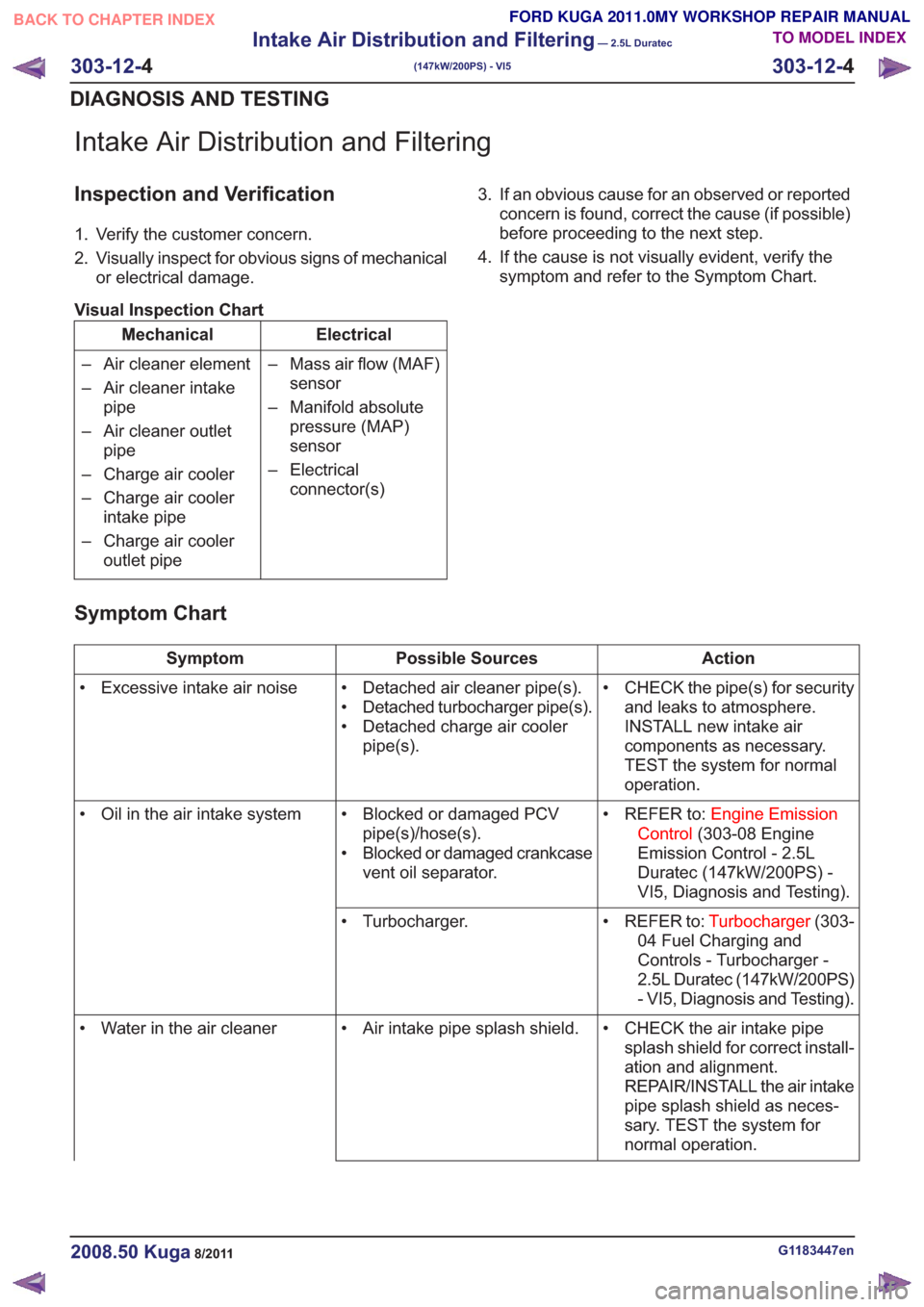
Intake Air Distribution and Filtering
Inspection and Verification
1. Verify the customer concern.
2. Visually inspect for obvious signs of mechanicalor electrical damage.
Visual Inspection Chart
Electrical
Mechanical
– Mass air flow (MAF)sensor
– Manifold absolute pressure (MAP)
sensor
– Electrical connector(s)
– Air cleaner element
– Air cleaner intake
pipe
– Air cleaner outlet pipe
– Charge air cooler
– Charge air cooler intake pipe
– Charge air cooler outlet pipe 3. If an obvious cause for an observed or reported
concern is found, correct the cause (if possible)
before proceeding to the next step.
4. If the cause is not visually evident, verify the symptom and refer to the Symptom Chart.
Symptom Chart
Action
Possible Sources
Symptom
• CHECK the pipe(s) for securityand leaks to atmosphere.
INSTALL new intake air
components as necessary.
TEST the system for normal
operation.
• Detached air cleaner pipe(s).
• Detached turbocharger pipe(s).
• Detached charge air cooler
pipe(s).
• Excessive intake air noise
• REFER to:Engine Emission
Control (303-08 Engine
Emission Control - 2.5L
Duratec (147kW/200PS) -
VI5, Diagnosis and Testing).
• Blocked or damaged PCV
pipe(s)/hose(s).
• Blocked or damaged crankcase vent oil separator.
• Oil in the air intake system
• REFER to:Turbocharger(303-
04 Fuel Charging and
Controls - Turbocharger -
2.5L Duratec (147kW/200PS)
- VI5, Diagnosis and Testing).
• Turbocharger.
• CHECK the air intake pipesplash shield for correct install-
ation and alignment.
REPAIR/INSTALL the air intake
pipe splash shield as neces-
sary. TEST the system for
normal operation.
• Air intake pipe splash shield.
• Water in the air cleaner
G1183447en2008.50 Kuga8/2011
303-12- 4
Intake Air Distribution and Filtering
— 2.5L Duratec
(147kW/200PS) - VI5
303-12- 4
DIAGNOSIS AND TESTING
TO MODEL INDEX
BACK TO CHAPTER INDEX
FORD KUGA 2011.0MY WORKSHOP REPAIR MANUAL