Page 1708 of 2057
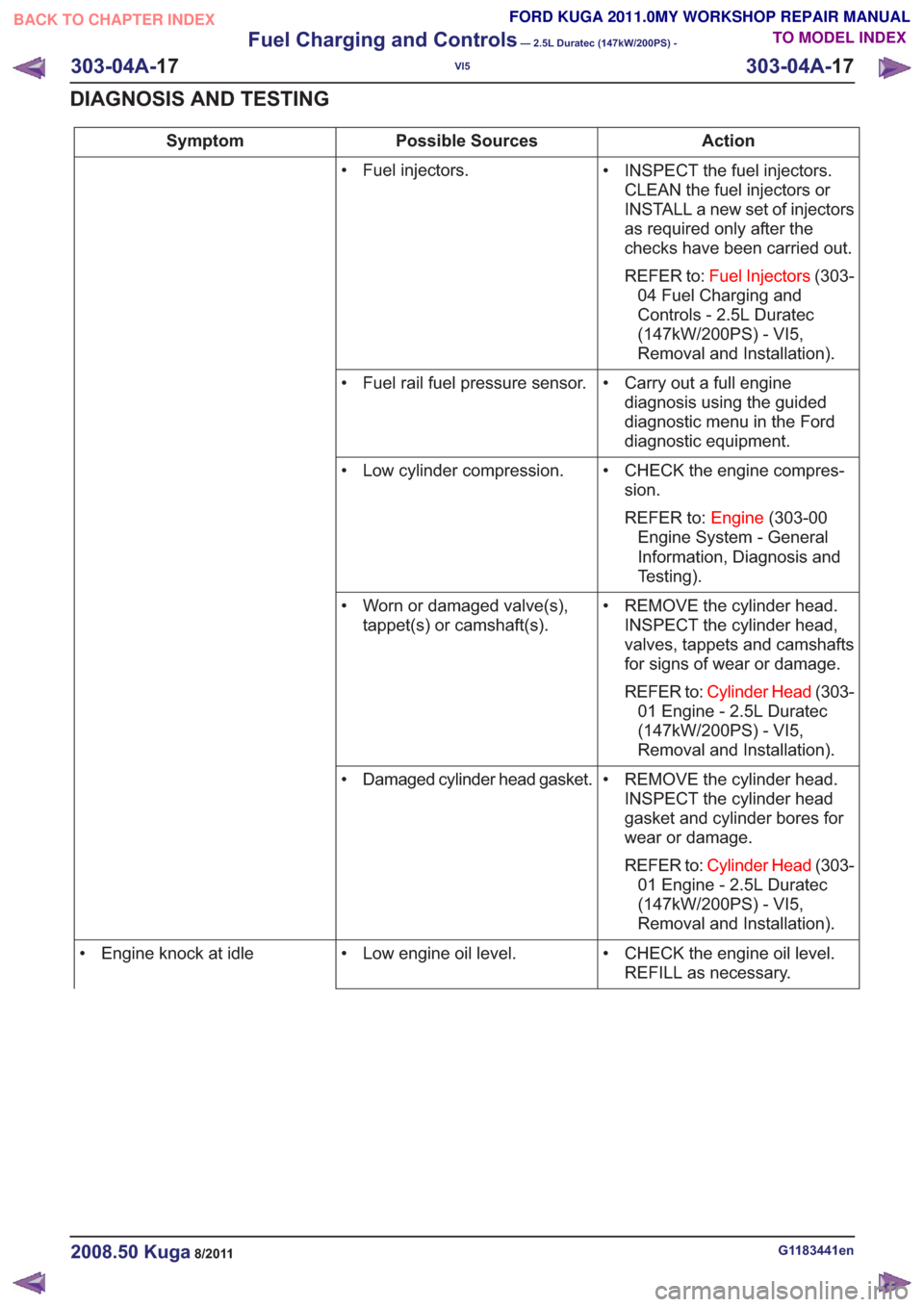
Action
Possible Sources
Symptom
• INSPECT the fuel injectors.CLEAN the fuel injectors or
INSTALL a new set of injectors
as required only after the
checks have been carried out.
REFER to: Fuel Injectors (303-
04 Fuel Charging and
Controls - 2.5L Duratec
(147kW/200PS) - VI5,
Removal and Installation).
• Fuel injectors.
• Carry out a full enginediagnosis using the guided
diagnostic menu in the Ford
diagnostic equipment.
• Fuel rail fuel pressure sensor.
• CHECK the engine compres-sion.
REFER to: Engine(303-00
Engine System - General
Information, Diagnosis and
Testing).
• Low cylinder compression.
• REMOVE the cylinder head.INSPECT the cylinder head,
valves, tappets and camshafts
for signs of wear or damage.
REFER to: Cylinder Head (303-
01 Engine - 2.5L Duratec
(147kW/200PS) - VI5,
Removal and Installation).
• Worn or damaged valve(s),
tappet(s) or camshaft(s).
• REMOVE the cylinder head.INSPECT the cylinder head
gasket and cylinder bores for
wear or damage.
REFER to: Cylinder Head (303-
01 Engine - 2.5L Duratec
(147kW/200PS) - VI5,
Removal and Installation).
• Damaged cylinder head gasket.
• CHECK the engine oil level.REFILL as necessary.
• Low engine oil level.
• Engine knock at idle
G1183441en2008.50 Kuga8/2011
303-04A- 17
Fuel Charging and Controls
— 2.5L Duratec (147kW/200PS) -
VI5
303-04A- 17
DIAGNOSIS AND TESTING
TO MODEL INDEX
BACK TO CHAPTER INDEX
FORD KUGA 2011.0MY WORKSHOP REPAIR MANUAL
Page 1709 of 2057
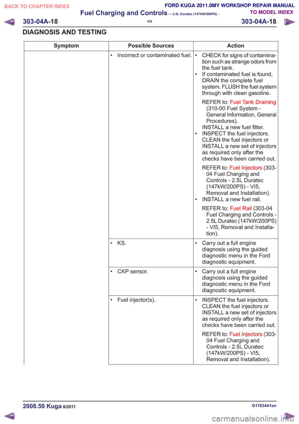
Action
Possible Sources
Symptom
• CHECK for signs of contamina-tion such as strange odors from
the fuel tank.
• If contaminated fuel is found, DRAIN the complete fuel
system. FLUSH the fuel system
through with clean gasoline.
REFER to: Fuel Tank Draining
(310-00 Fuel System -
General Information, General
Procedures).
INSTALL a new fuel filter.
• INSPECT the fuel injectors. CLEAN the fuel injectors or
INSTALL a new set of injectors
as required only after the
checks have been carried out.
REFER to: Fuel Injectors (303-
04 Fuel Charging and
Controls - 2.5L Duratec
(147kW/200PS) - VI5,
Removal and Installation).
• INSTALL a new fuel rail.
REFER to: Fuel Rail(303-04
Fuel Charging and Controls -
2.5L Duratec (147kW/200PS)
- VI5, Removal and Installa-
tion).
• Incorrect or contaminated fuel.
• Carry out a full enginediagnosis using the guided
diagnostic menu in the Ford
diagnostic equipment.
• KS.
• Carry out a full enginediagnosis using the guided
diagnostic menu in the Ford
diagnostic equipment.
• CKP sensor.
• INSPECT the fuel injectors.CLEAN the fuel injectors or
INSTALL a new set of injectors
as required only after the
checks have been carried out.
REFER to: Fuel Injectors (303-
04 Fuel Charging and
Controls - 2.5L Duratec
(147kW/200PS) - VI5,
Removal and Installation).
• Fuel injector(s).
G1183441en2008.50 Kuga8/2011
303-04A-
18
Fuel Charging and Controls
— 2.5L Duratec (147kW/200PS) -
VI5
303-04A- 18
DIAGNOSIS AND TESTING
TO MODEL INDEX
BACK TO CHAPTER INDEX
FORD KUGA 2011.0MY WORKSHOP REPAIR MANUAL
Page 1710 of 2057
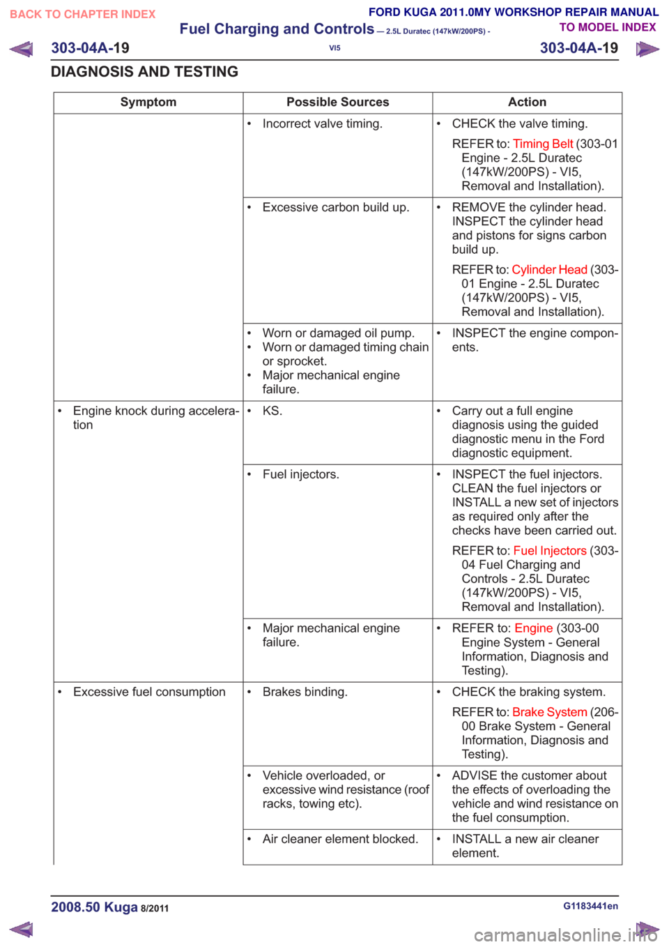
Action
Possible Sources
Symptom
• CHECK the valve timing.REFER to: Timing Belt (303-01
Engine - 2.5L Duratec
(147kW/200PS) - VI5,
Removal and Installation).
• Incorrect valve timing.
• REMOVE the cylinder head.INSPECT the cylinder head
and pistons for signs carbon
build up.
REFER to: Cylinder Head (303-
01 Engine - 2.5L Duratec
(147kW/200PS) - VI5,
Removal and Installation).
• Excessive carbon build up.
• INSPECT the engine compon-ents.
• Worn or damaged oil pump.
• Worn or damaged timing chain
or sprocket.
• Major mechanical engine failure.
• Carry out a full enginediagnosis using the guided
diagnostic menu in the Ford
diagnostic equipment.
• KS.
• Engine knock during accelera-
tion
• INSPECT the fuel injectors.CLEAN the fuel injectors or
INSTALL a new set of injectors
as required only after the
checks have been carried out.
REFER to: Fuel Injectors (303-
04 Fuel Charging and
Controls - 2.5L Duratec
(147kW/200PS) - VI5,
Removal and Installation).
• Fuel injectors.
• REFER to:Engine(303-00
Engine System - General
Information, Diagnosis and
Testing).
• Major mechanical engine
failure.
• CHECK the braking system.REFER to: Brake System (206-
00 Brake System - General
Information, Diagnosis and
Testing).
• Brakes binding.
• Excessive fuel consumption
• ADVISE the customer aboutthe effects of overloading the
vehicle and wind resistance on
the fuel consumption.
• Vehicle overloaded, or
excessive wind resistance (roof
racks, towing etc).
• INSTALL a new air cleanerelement.
• Air cleaner element blocked.
G1183441en2008.50 Kuga8/2011
303-04A-
19
Fuel Charging and Controls
— 2.5L Duratec (147kW/200PS) -
VI5
303-04A- 19
DIAGNOSIS AND TESTING
TO MODEL INDEX
BACK TO CHAPTER INDEX
FORD KUGA 2011.0MY WORKSHOP REPAIR MANUAL
Page 1711 of 2057
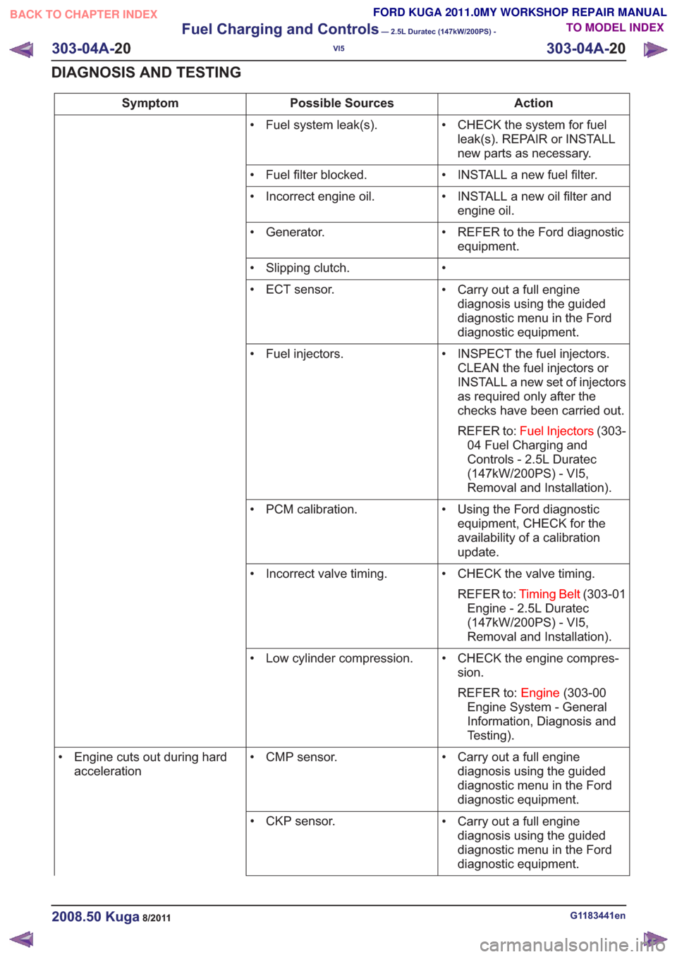
Action
Possible Sources
Symptom
• CHECK the system for fuelleak(s). REPAIR or INSTALL
new parts as necessary.
• Fuel system leak(s).
• INSTALL a new fuel filter.
• Fuel filter blocked.
• INSTALL a new oil filter andengine oil.
• Incorrect engine oil.
• REFER to the Ford diagnosticequipment.
• Generator.
•
• Slipping clutch.
• Carry out a full enginediagnosis using the guided
diagnostic menu in the Ford
diagnostic equipment.
• ECT sensor.
• INSPECT the fuel injectors.CLEAN the fuel injectors or
INSTALL a new set of injectors
as required only after the
checks have been carried out.
REFER to: Fuel Injectors (303-
04 Fuel Charging and
Controls - 2.5L Duratec
(147kW/200PS) - VI5,
Removal and Installation).
• Fuel injectors.
• Using the Ford diagnosticequipment, CHECK for the
availability of a calibration
update.
• PCM calibration.
• CHECK the valve timing.REFER to: Timing Belt (303-01
Engine - 2.5L Duratec
(147kW/200PS) - VI5,
Removal and Installation).
• Incorrect valve timing.
• CHECK the engine compres-sion.
REFER to: Engine(303-00
Engine System - General
Information, Diagnosis and
Testing).
• Low cylinder compression.
• Carry out a full enginediagnosis using the guided
diagnostic menu in the Ford
diagnostic equipment.
• CMP sensor.
• Engine cuts out during hard
acceleration
• Carry out a full enginediagnosis using the guided
diagnostic menu in the Ford
diagnostic equipment.
• CKP sensor.
G1183441en2008.50 Kuga8/2011
303-04A-
20
Fuel Charging and Controls
— 2.5L Duratec (147kW/200PS) -
VI5
303-04A- 20
DIAGNOSIS AND TESTING
TO MODEL INDEX
BACK TO CHAPTER INDEX
FORD KUGA 2011.0MY WORKSHOP REPAIR MANUAL
Page 1712 of 2057
Action
Possible Sources
Symptom
• Carry out a full enginediagnosis using the guided
diagnostic menu in the Ford
diagnostic equipment.
• Fuel rail fuel pressure sensor.
• Check the fuel system pres-sure.
• Low fuel system pressure.
G1183441en2008.50 Kuga8/2011
303-04A-
21
Fuel Charging and Controls
— 2.5L Duratec (147kW/200PS) -
VI5
303-04A- 21
DIAGNOSIS AND TESTING
TO MODEL INDEX
BACK TO CHAPTER INDEX
FORD KUGA 2011.0MY WORKSHOP REPAIR MANUAL
Page 1715 of 2057
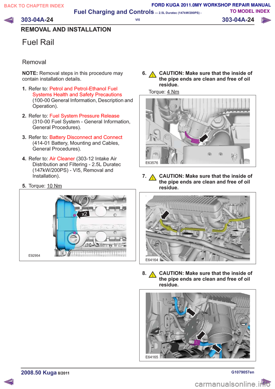
Fuel Rail
Removal
NOTE:Removal steps in this procedure may
contain installation details.
1. Refer to: Petrol and Petrol-Ethanol Fuel
Systems Health and Safety Precautions
(100-00 General Information, Description and
Operation).
2. Refer to: Fuel System Pressure Release
(310-00 Fuel System - General Information,
General Procedures).
3. Refer to: Battery Disconnect and Connect
(414-01 Battery, Mounting and Cables,
General Procedures).
4. Refer to: Air Cleaner (303-12 Intake Air
Distribution and Filtering - 2.5L Duratec
(147kW/200PS) - VI5, Removal and
Installation).
5. Torque: 10
Nm
x2x2
E92954
6. CAUTION: Make sure that the inside of
the pipe ends are clean and free of oil
residue.
Torque: 4Nm
E63576
7. CAUTION: Make sure that the inside ofthe pipe ends are clean and free of oil
residue.
E64164
8. CAUTION: Make sure that the inside ofthe pipe ends are clean and free of oil
residue.
E64165
G1079057en2008.50 Kuga8/2011
303-04A- 24
Fuel Charging and Controls
— 2.5L Duratec (147kW/200PS) -
VI5
303-04A- 24
REMOVAL AND INSTALLATION
TO MODEL INDEX
BACK TO CHAPTER INDEX
FORD KUGA 2011.0MY WORKSHOP REPAIR MANUAL
Page 1717 of 2057
SECTION 303-04B Fuel Charging and Controls -
Turbocharger
— 2.5L Duratec (147kW/200PS) - VI5
VEHICLE APPLICATION:2008.50 Kuga
PA G E
CONTENTS
DESCRIPTION AND OPERATION
303-04B-2
Turbocharger (Component Location) ........................................................................\
..........
303-04B-4
Turbocharger (Overview) ........................................................................\
............................
303-04B-4
Turbocharger(s) ........................................................................\
..........................................
303-04B-5
Turbocharger (System Operation and Component Description) ........................................
303-04B-5
System Diagram ........................................................................\
.........................................
303-04B-6
System Operation ........................................................................\
.......................................
303-04B-6
Turbocharger(s) ........................................................................\
......................................
303-04B-6
Turbocharger boost pressure control ........................................................................\
......
303-04B-7
Recirculated air valve ........................................................................\
.............................
303-04B-7
Component Description ........................................................................\
..............................
303-04B-7
Wastegate control valve ........................................................................\
..........................
303-04B-7
Recirculated air valve ........................................................................\
.............................
DIAGNOSIS AND TESTING 303-04B-9
Turbocharger ........................................................................\
..............................................
303-04B-9
Inspection and Verification ........................................................................\
..........................
REMOVAL AND INSTALLATION 303-04B-11
(23 612 0)
Turbocharger ........................................................................\
..........................
303-04B-1
Fuel Charging and Controls - Turbocharger
—
2.5L Duratec (147kW/200PS) - VI5
303-04B- 1
.
TO MODEL INDEX
BACK TO CHAPTER INDEX
FORD KUGA 2011.0MY WORKSHOP REPAIR MANUAL
Page 1721 of 2057
Turbocharger – System Operation and Component Description
System Diagram
346
7
8
10
11
12
1415
25
13
7
9
1346
7
8
10
11
12
1415
25
13
7
9
E98961
Description
Item
Turbo boost pressure controller
1
from exhaust manifold
2
Pilot pressure
3Description
Item
Wastegate control valveRefertoComponentDescription:(page
7)
Comments: closed when de-energised
4
G1032426en2008.50 Kuga8/2011
303-04B-
5
Fuel Charging and Controls - Turbocharger
—
2.5L Duratec (147kW/200PS) - VI5
303-04B- 5
DESCRIPTION AND OPERATION
TO MODEL INDEX
BACK TO CHAPTER INDEX
FORD KUGA 2011.0MY WORKSHOP REPAIR MANUAL