2011 FORD KUGA filter
[x] Cancel search: filterPage 1921 of 2057
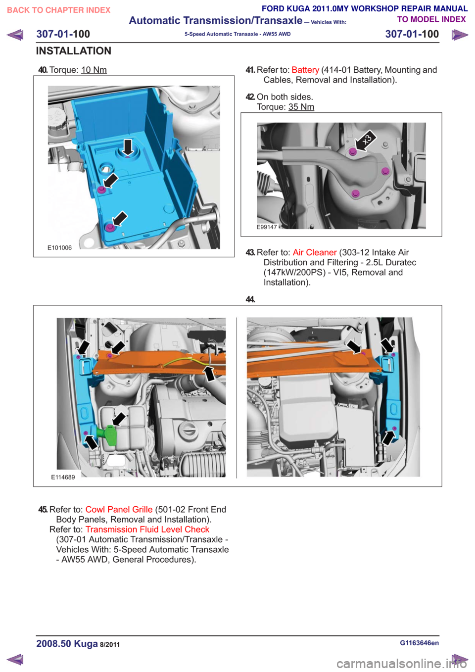
40.Torque: 10Nm
E101006
41.Refer to: Battery(414-01 Battery, Mounting and
Cables, Removal and Installation).
42. On both sides.
Torque: 35
Nm
E99147
x3
43.Refer to: Air Cleaner (303-12 Intake Air
Distribution and Filtering - 2.5L Duratec
(147kW/200PS) - VI5, Removal and
Installation).
44.
E114689
45. Refer to: Cowl Panel Grille (501-02 Front End
Body Panels, Removal and Installation).
Refer to: Transmission Fluid Level Check
(307-01 Automatic Transmission/Transaxle -
Vehicles With: 5-Speed Automatic Transaxle
- AW55 AWD, General Procedures).
G1163646en2008.50 Kuga8/2011
307-01- 100
Automatic Transmission/Transaxle
— Vehicles With:
5-Speed Automatic Transaxle - AW55 AWD
307-01- 100
INSTALLATION
TO MODEL INDEX
BACK TO CHAPTER INDEX
FORD KUGA 2011.0MY WORKSHOP REPAIR MANUAL
Page 1986 of 2057
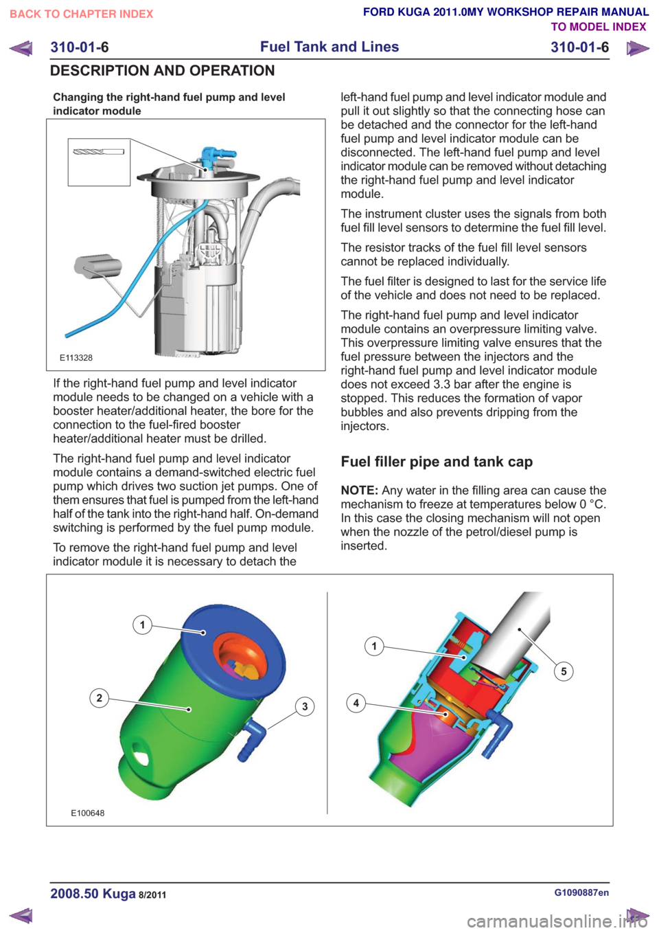
Changing the right-hand fuel pump and level
indicator module
E113328
If the right-hand fuel pump and level indicator
module needs to be changed on a vehicle with a
booster heater/additional heater, the bore for the
connection to the fuel-fired booster
heater/additional heater must be drilled.
The right-hand fuel pump and level indicator
module contains a demand-switched electric fuel
pump which drives two suction jet pumps. One of
them ensures that fuel is pumped from the left-hand
half of the tank into the right-hand half. On-demand
switching is performed by the fuel pump module.
To remove the right-hand fuel pump and level
indicator module it is necessary to detach theleft-hand fuel pump and level indicator module and
pull it out slightly so that the connecting hose can
be detached and the connector for the left-hand
fuel pump and level indicator module can be
disconnected. The left-hand fuel pump and level
indicator module can be removed without detaching
the right-hand fuel pump and level indicator
module.
The instrument cluster uses the signals from both
fuel fill level sensors to determine the fuel fill level.
The resistor tracks of the fuel fill level sensors
cannot be replaced individually.
The fuel filter is designed to last for the service life
of the vehicle and does not need to be replaced.
The right-hand fuel pump and level indicator
module contains an overpressure limiting valve.
This overpressure limiting valve ensures that the
fuel pressure between the injectors and the
right-hand fuel pump and level indicator module
does not exceed 3.3 bar after the engine is
stopped. This reduces the formation of vapor
bubbles and also prevents dripping from the
injectors.
Fuel filler pipe and tank cap
NOTE:
Any water in the filling area can cause the
mechanism to freeze at temperatures below 0 °C.
In this case the closing mechanism will not open
when the nozzle of the petrol/diesel pump is
inserted.
43
1
2
1
5
43
1
2
1
5
E100648
G1090887en2008.50 Kuga8/2011
310-01- 6
Fuel Tank and Lines
310-01- 6
DESCRIPTION AND OPERATION
TO MODEL INDEX
BACK TO CHAPTER INDEX
FORD KUGA 2011.0MY WORKSHOP REPAIR MANUAL
Page 2028 of 2057
SECTION 412-01 Climate Control
VEHICLE APPLICATION:2008.50 Kuga
PA G E
CONTENTS
SPECIFICATIONS
412-01-3
Specifications ........................................................................\
..............................................
DESCRIPTION AND OPERATION 412-01-4
Climate Control (Component Location) ........................................................................\
......
412-01-10
Climate Control (Overview) ........................................................................\
........................
412-01-10
Pollen filter ........................................................................\
..................................................
412-01-10
Heat exchanger ........................................................................\
..........................................
412-01-10
Evaporator assembly ........................................................................\
..................................
412-01-10
Blower motor ........................................................................\
..............................................
412-01-11
Fault Memory Interrogation without diagnostics unit - vehicles with automatic temperature
control ........................................................................\
.......................................................
412-01-11
Switch over from Celsius to Fahrenheit ........................................................................\
......
412-01-12
Climate Control (System Operation and Component Description) .....................................
412-01-12
System Diagram ........................................................................\
.........................................
412-01-19
System Operation ........................................................................\
.......................................
412-01-19
Climate control housing ........................................................................\
..........................
412-01-22
Climate control ........................................................................\
........................................
412-01-24
Component Description ........................................................................\
..............................
412-01-24
Air conditioning compressor ........................................................................\
...................
412-01-24
Pollen filter ........................................................................\
..............................................
412-01-24
Control assembly, climate control - vehicles with manual temperature control ..............
412-01-25
Control assembly, climate control - vehicles with automatic temperature control ...........
412-01-25
Control assembly, climate control - vehicles with DVD navigation system with a touch
screen........................................................................\
................................................... 412-01-25
Climate control module - vehicles with DVD navigation system with a touch screen.....
412-01-25
Sun sensor - vehicles with automatic temperature control .............................................
412-01-26
In-vehicle temperature sensor ........................................................................\
................
412-01-26
Ambient temperature sensor ........................................................................\
..................
412-01-26
Blower motor ........................................................................\
...........................................
412-01-26
Blower control module - vehicles equipped with automatic temperature control ............
REMOVAL AND INSTALLATION 412-01-28
(34 626 4)
Air Conditioning (A/C) Compressor — 2.5L Duratec (147kW/200PS) - VI5 ....
412-01-29
Air Conditioning (A/C) Compressor to Condenser Discharge Line .....................................
412-01-30
Air Conditioning (A/C) Compressor to Condenser Discharge Line — 2.5L Duratec
(147kW/200PS) - VI5 ........................................................................\
................................
412-01-31
Condenser ........................................................................\
..................................................
412-01-35
Clutch and Clutch Field Coil........................................................................\
.......................
412-01-36
Pollen Filter — RHD........................................................................\
...................................
412-01-37
(34
374 0)
Blower Motor — RHD ........................................................................\
.............
412-01-40
(34 382 0)
Blower Motor Resistor — Vehicles With: Manual Temperature Control, RHD .
412-01-41
(34 382 0)
Blower Motor Resistor — Vehicles With: Dual Automatic Temperature
Control ........................................................................\
..................................
412-01- 1
Climate Control
412-01- 1
.
TO MODEL INDEX
BACK TO CHAPTER INDEX
PAGE 1 OF 2 FORD KUGA 2011.0MY WORKSHOP REPAIR MANUAL
Page 2037 of 2057
Climate Control – Overview
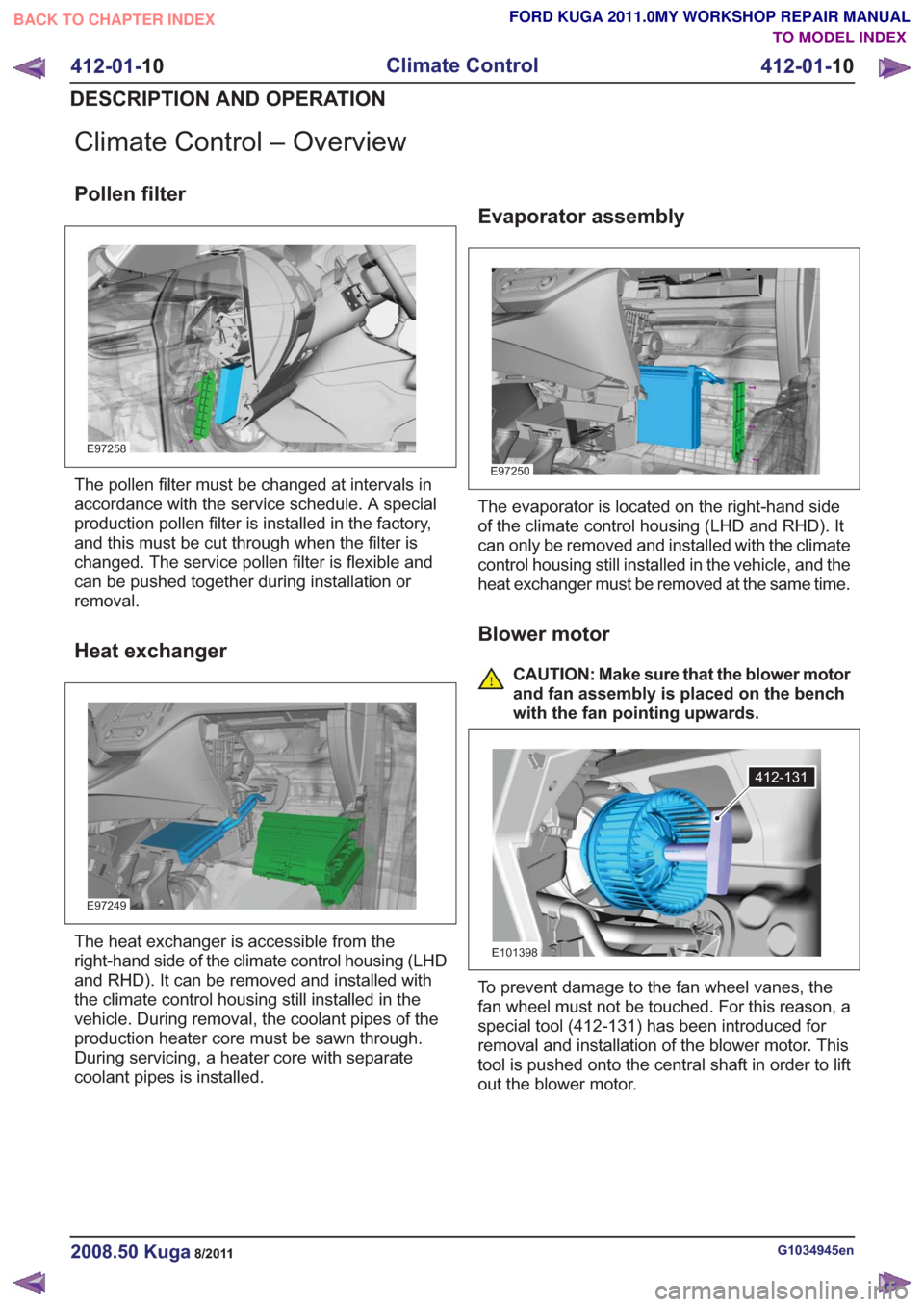
Pollen filter
E97258
The pollen filter must be changed at intervals in
accordance with the service schedule. A special
production pollen filter is installed in the factory,
and this must be cut through when the filter is
changed. The service pollen filter is flexible and
can be pushed together during installation or
removal.
Heat exchanger
E97249
The heat exchanger is accessible from the
right-hand side of the climate control housing (LHD
and RHD). It can be removed and installed with
the climate control housing still installed in the
vehicle. During removal, the coolant pipes of the
production heater core must be sawn through.
During servicing, a heater core with separate
coolant pipes is installed.
Evaporator assembly
E97250
The evaporator is located on the right-hand side
of the climate control housing (LHD and RHD). It
can only be removed and installed with the climate
control housing still installed in the vehicle, and the
heat exchanger must be removed at the same time.
Blower motor
CAUTION: Make sure that the blower motor
and fan assembly is placed on the bench
with the fan pointing upwards.
412-131
E101398
To prevent damage to the fan wheel vanes, the
fan wheel must not be touched. For this reason, a
special tool (412-131) has been introduced for
removal and installation of the blower motor. This
tool is pushed onto the central shaft in order to lift
out the blower motor.
G1034945en2008.50 Kuga8/2011
412-01-10
Climate Control
412-01- 10
DESCRIPTION AND OPERATION
TO MODEL INDEX
BACK TO CHAPTER INDEX
FORD KUGA 2011.0MY WORKSHOP REPAIR MANUAL
Page 2047 of 2057
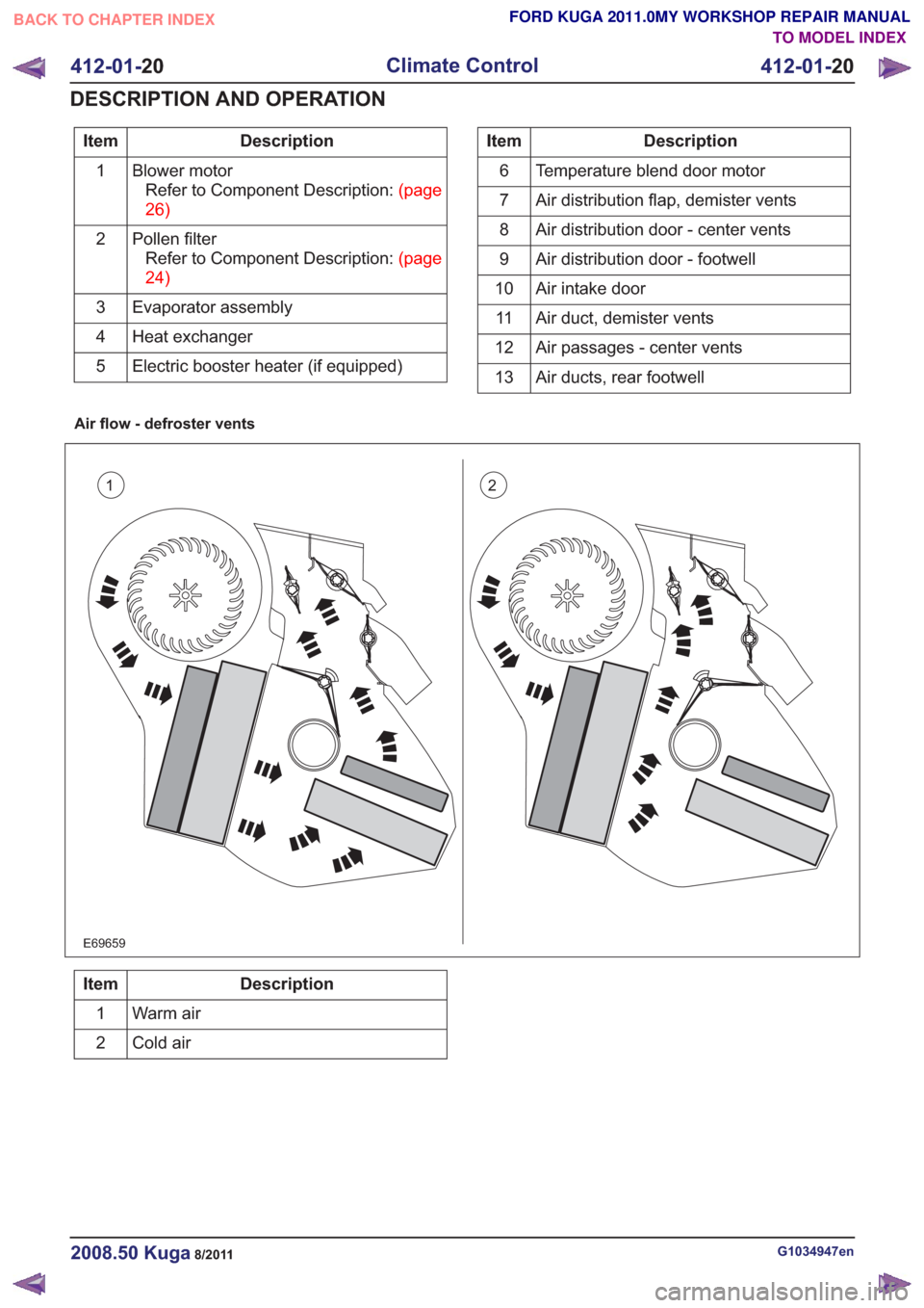
Description
Item
Blower motorRefertoComponentDescription:(page
26)
1
Pollen filterRefertoComponentDescription:(page
24)
2
Evaporator assembly
3
Heat exchanger
4
Electric booster heater (if equipped)
5Description
Item
Temperature blend door motor
6
Air distribution flap, demister vents
7
Air distribution door - center vents
8
Air distribution door - footwell
9
Air intake door
10
Air duct, demister vents
11
Air passages - center vents
12
Air ducts, rear footwell
13
Air flow - defroster vents
12
E69659
Description
Item
Warm air
1
Cold air
2
G1034947en2008.50 Kuga8/2011
412-01- 20
Climate Control
412-01- 20
DESCRIPTION AND OPERATION
TO MODEL INDEX
BACK TO CHAPTER INDEX
FORD KUGA 2011.0MY WORKSHOP REPAIR MANUAL
Page 2051 of 2057
permitted, the high-pressure switch turns off the
refrigerant compressor.
The compressor on-off cycle is controlled by the
dual pressure switch depending on the pressure
in the refrigerant accumulator. The dual pressure
switch turns the refrigerant compressor off
permanently if the pressure falls below a permitted
value (e.g. if there is a leak).
Component Description
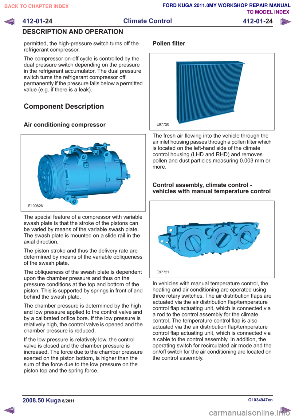
Air conditioning compressor
E100826
The special feature of a compressor with variable
swash plate is that the stroke of the pistons can
be varied by means of the variable swash plate.
The swash plate is mounted on a slide rail in the
axial direction.
The piston stroke and thus the delivery rate are
determined by means of the variable obliqueness
of the swash plate.
The obliqueness of the swash plate is dependent
upon the chamber pressure and thus on the
pressure conditions at the top and bottom of the
piston. This is supported by springs in front of and
behind the swash plate.
The chamber pressure is determined by the high
and low pressure applied to the control valve and
by a calibrated orifice bore. If the low pressure is
relatively high, the control valve is opened and the
chamber pressure is reduced.
If the low pressure is relatively low, the control
valve is closed and the chamber pressure is
increased. The force due to the chamber pressure
exerted on the piston bottom, is higher than the
sum of the force due to the low pressure on the
piston top and the spring force.
Pollen filter
E97720
The fresh air flowing into the vehicle through the
air inlet housing passes through a pollen filter which
is located on the left-hand side of the climate
control housing (LHD and RHD) and removes
pollen and dust particles measuring 0.003 mm or
more.
Control assembly, climate control -
vehicles with manual temperature control
E97721
In vehicles with manual temperature control, the
heating and air conditioning are operated using
three rotary switches. The air distribution flaps are
actuated via the air distribution flap/temperature
control flap actuating unit, which is connected via
a rod to the control assembly for the climate
control. The temperature control flap is also
actuated via the air distribution flap/temperature
control flap actuating unit, which is connected via
a cable to the control assembly. In addition, the
operating switch for recirculated air mode and the
on/off switch for the air conditioning are located on
the control assembly.
G1034947en2008.50 Kuga8/2011
412-01-24
Climate Control
412-01- 24
DESCRIPTION AND OPERATION
TO MODEL INDEX
BACK TO CHAPTER INDEX
FORD KUGA 2011.0MY WORKSHOP REPAIR MANUAL