Page 1333 of 2057
Installation
1.On both sides.
E101644
2.On both sides.
Torque: 1
15Nm
E101643
3. NOTE: Only tighten the bolt finger tight at this
stage.
On both sides.
E101641
4. Fabricate a spacer.
E69209
226
40
5.On both sides.
General Equipment: Transmission Jack
G1058429en2008.50 Kuga8/2011
205-05- 5
Rear Drive Halfshafts
205-05- 5
REMOVAL AND INSTALLATION
TO MODEL INDEX
BACK TO CHAPTER INDEX
FORD KUGA 2011.0MY WORKSHOP REPAIR MANUAL
Page 1334 of 2057
1
2
E93313
6.On both sides.
Torque: 130
Nm
E101642
7.Remove the following items:
1. Spacer
2. General Equipment: Transmission Jack
8. On both sides.
Torque: 5
Nm
E114252
G1058429en2008.50 Kuga8/2011
205-05- 6
Rear Drive Halfshafts
205-05- 6
REMOVAL AND INSTALLATION
TO MODEL INDEX
BACK TO CHAPTER INDEX
FORD KUGA 2011.0MY WORKSHOP REPAIR MANUAL
Page 1482 of 2057

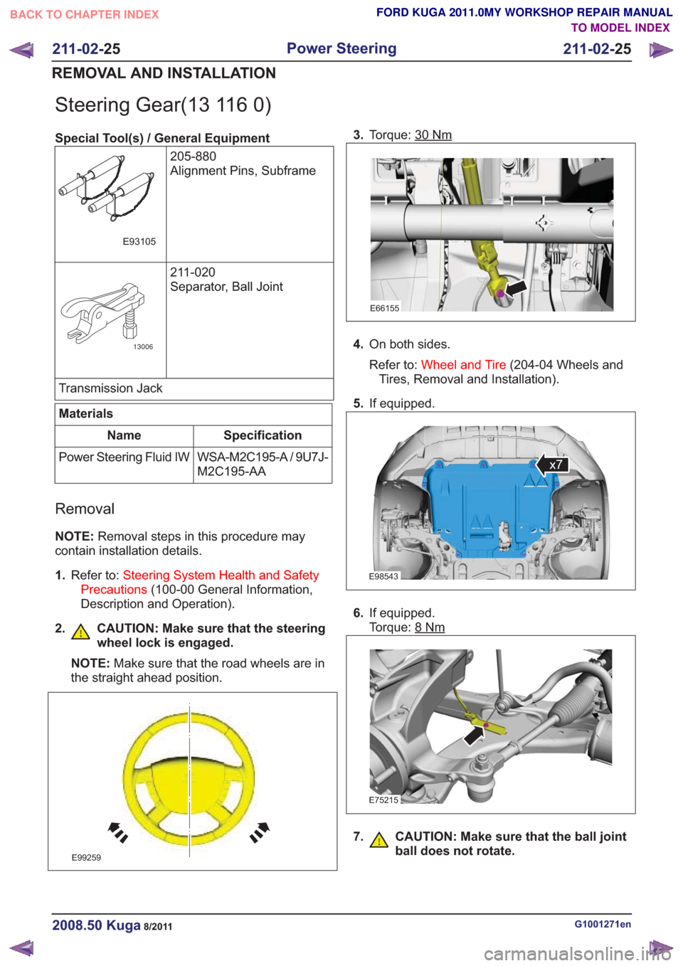
Steering Gear(13 116 0)
Special Tool(s) / General Equipment205-880
Alignment Pins, Subframe
E93105
211-020
Separator, Ball Joint
13006
Transmission Jack
Materials
Specification
Name
WSA-M2C195-A / 9U7J-
M2C195-AA
Power Steering Fluid IW
Removal
NOTE:
Removal steps in this procedure may
contain installation details.
1. Refer to: Steering System Health and Safety
Precautions (100-00 General Information,
Description and Operation).
2. CAUTION: Make sure that the steering wheel lock is engaged.
NOTE: Make sure that the road wheels are in
the straight ahead position.
E99259
3. Torque: 30Nm
E66155
4.On both sides.
Refer to: Wheel and Tire (204-04 Wheels and
Tires, Removal and Installation).
5. If equipped.
E98543
x7
6.If equipped.
Torque: 8
Nm
E75215
7. CAUTION: Make sure that the ball joint
ball does not rotate.
G1001271en2008.50 Kuga8/2011
211-02- 25
Power Steering
211-02- 25
REMOVAL AND INSTALLATION
TO MODEL INDEX
BACK TO CHAPTER INDEX
FORD KUGA 2011.0MY WORKSHOP REPAIR MANUAL
Page 1485 of 2057
E99250
16.General Equipment: Transmission Jack
E99060
17.Remove the following items:
1. Torque: 70
Nm
2. Torque: • Stage 1: 140
Nm
• Stage 2: 180°
3. Torque: 125Nm
G1001271en2008.50 Kuga8/2011
211-02- 28
Power Steering
211-02- 28
REMOVAL AND INSTALLATION
TO MODEL INDEX
BACK TO CHAPTER INDEX
FORD KUGA 2011.0MY WORKSHOP REPAIR MANUAL
Page 1525 of 2057

Action
Possible Sources
Symptom
• CHECK the engine compon-ents for wear or damage. Make
sure that all components are
within specification. INSTALL
new components as necessary.
Engine - 2.5L Duratec-ST (VI5)
-
REFER to: Specifications (303-
01 Engine - 2.5L Duratec
(147kW/200PS) - VI5,
Specifications).
Engine - 2.0L Duratorq-TDCi
(DW) Diesel -
• Engine components
- Pistons.
- Piston rings.
- Connecting rod big end,main bearing or thrust
bearing journals.
- Connecting rods bent or damaged.
• Noisy running or engine noise
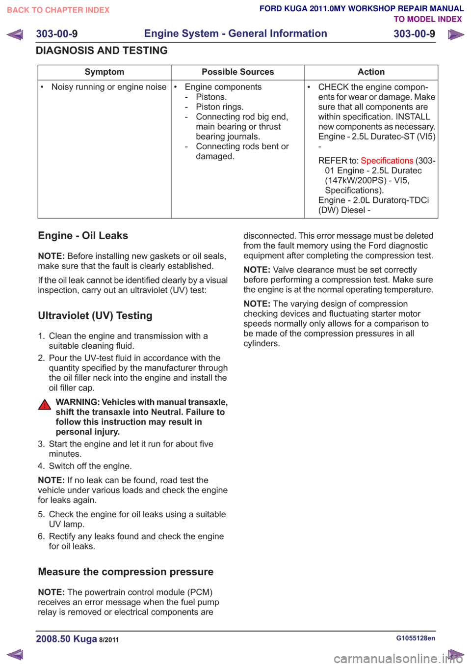
Engine - Oil Leaks
NOTE:
Before installing new gaskets or oil seals,
make sure that the fault is clearly established.
If the oil leak cannot be identified clearly by a visual
inspection, carry out an ultraviolet (UV) test:
Ultraviolet (UV) Testing
1. Clean the engine and transmission with a suitable cleaning fluid.
2. Pour the UV-test fluid in accordance with the quantity specified by the manufacturer through
the oil filler neck into the engine and install the
oil filler cap.
WARNING: Vehicles with manual transaxle,
shift the transaxle into Neutral. Failure to
follow this instruction may result in
personal injury.
3. Start the engine and let it run for about five minutes.
4. Switch off the engine.
NOTE: If no leak can be found, road test the
vehicle under various loads and check the engine
for leaks again.
5. Check the engine for oil leaks using a suitable UV lamp.
6. Rectify any leaks found and check the engine for oil leaks.
Measure the compression pressure
NOTE: The powertrain control module (PCM)
receives an error message when the fuel pump
relay is removed or electrical components are disconnected. This error message must be deleted
from the fault memory using the Ford diagnostic
equipment after completing the compression test.
NOTE:
Valve clearance must be set correctly
before performing a compression test. Make sure
the engine is at the normal operating temperature.
NOTE: The varying design of compression
checking devices and fluctuating starter motor
speeds normally only allows for a comparison to
be made of the compression pressures in all
cylinders.
G1055128en2008.50 Kuga8/2011
303-00- 9
Engine System - General Information
303-00- 9
DIAGNOSIS AND TESTING
TO MODEL INDEX
BACK TO CHAPTER INDEX
FORD KUGA 2011.0MY WORKSHOP REPAIR MANUAL
Page 1589 of 2057
Crankshaft Rear Seal(21 468 4)
Special Tool(s)303-1181
Installer, Crankshaft Rear
Seal
E62048
303-254
Locking Tool, Flywheel
21135
303-293
Remover, Crankshaft Seal
21143
Removal
Vehicles with manual transmission
1.
Vehicles with automatic transmission
2.Refer to: Transmission (307-01 Automatic
Transmission/Transaxle - Vehicles With:
5-Speed Automatic Transaxle - AW55 AWD,
Removal).
All vehicles
3. Special Tool(s): 303-254
E64889
4.Special Tool(s): 303-293
E64890
303-293
G1268481en2008.50 Kuga8/2011
303-01- 56
Engine— 2.5L Duratec (147kW/200PS) - VI5303-01-
56
REMOVAL AND INSTALLATION
TO MODEL INDEX
BACK TO CHAPTER INDEX
FORD KUGA 2011.0MY WORKSHOP REPAIR MANUAL
Page 1590 of 2057

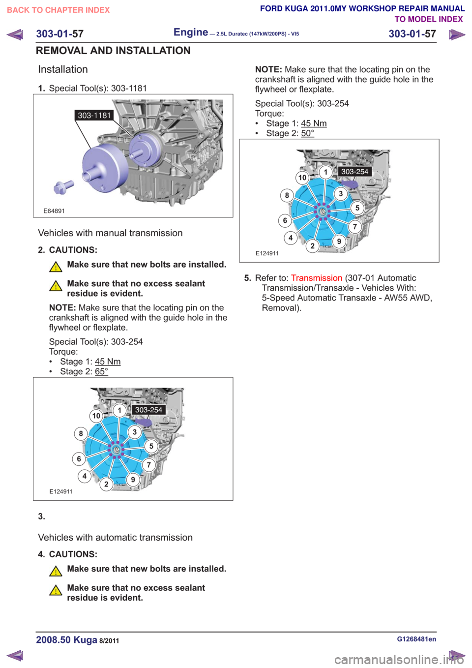
Installation
1.Special Tool(s): 303-1181
E64891
303-1181
Vehicles with manual transmission
2. CAUTIONS:
Make sure that new bolts are installed.
Make sure that no excess sealant
residue is evident.
NOTE: Make sure that the locating pin on the
crankshaft is aligned with the guide hole in the
flywheel or flexplate.
Special Tool(s): 303-254
Torque:
• Stage 1: 45
Nm
• Stage 2: 65°
E124911
1
2
3
4
5
67
8
9
10
3.
Vehicles with automatic transmission
4. CAUTIONS:
Make sure that new bolts are installed.
Make sure that no excess sealant
residue is evident. NOTE:
Make sure that the locating pin on the
crankshaft is aligned with the guide hole in the
flywheel or flexplate.
Special Tool(s): 303-254
Torque:
• Stage 1: 45
Nm
• Stage 2: 50°
E124911
1
2
3
4
5
67
8
9
10
5. Refer to: Transmission (307-01 Automatic
Transmission/Transaxle - Vehicles With:
5-Speed Automatic Transaxle - AW55 AWD,
Removal).
G1268481en2008.50 Kuga8/2011
303-01- 57
Engine— 2.5L Duratec (147kW/200PS) - VI5303-01-
57
REMOVAL AND INSTALLATION
TO MODEL INDEX
BACK TO CHAPTER INDEX
FORD KUGA 2011.0MY WORKSHOP REPAIR MANUAL
Page 1608 of 2057
E112535
1
2
62.General Equipment: Cable Ties
E112536
63. WARNING: Make sure that the engine
and transmission assembly is on
wooden blocks and secured with
suitable retaining straps.
General Equipment: Retaining Strap
General Equipment: Mounting Table Set
General Equipment: Wooden Block
G1191240en2008.50 Kuga8/2011
303-01- 75
Engine— 2.5L Duratec (147kW/200PS) - VI5303-01-
75
REMOVAL
TO MODEL INDEX
BACK TO CHAPTER INDEX
FORD KUGA 2011.0MY WORKSHOP REPAIR MANUAL