Page 461 of 2057

Generic Electronic Module (GEM)
Refer to Wiring Diagrams Section 419-10, for
schematic and connector information.
Special Tool(s) / General Equipment
Terminal Probe Kit
418-S035Digital multimeter
Ford approved diagnostic tool
Description of operation
A diagnosis of the generic electronic module (GEM)
can be performed with the Ford approved
diagnostic tool. Furthermore, an integrated service
mode enables testing of the input and output
signals without the need for further tools. To enable
activation of service mode:
• Switch off the ignition
• Switch off all other electrical consumers
• Apply the handbrake
• Shift to neutral
• Close the doors.
Activate service mode
Proceed as follows to activate service mode:
• PRESS and HOLD the switch of the heated rear
window
• SWITCH ON the ignition.
• RELEASE the switch of the heated rear window
A signal sounds and the turn signal lamps
illuminate to indicate that service mode has been
successfully activated.
NOTE: If the alarm is armed (in vehicles fitted with
an anti-theft alarm system), service mode cannot
be activated.
Input signals
SWITCH the windshield wiper switch to the "Off"
position to test the input signals. The following is
a list of the switch signals to be tested, in no
particular order: • Turn signals (right, left, hazard warning lights)
• Windshield wiper stage I
• Windshield wiper stage II
• Windshield washer system
• Rear window wiper
• Rear window washer system
• Doors open/closed
• Door key cylinder set/reset switch
• Remote control for central locking with double
locking
• Hood up/down (in vehicles fitted with anti-theft alarm system)
• Tailgate open/closed
• Mini liftgate open/closed
• Manual A/C request signal
• Manual AUX heater request signal
• Heated windshield (if fitted)
• Parking brake
• Brake fluid level
• Cruise control system
• Autolamps
• Dipped beam
• Main beam
• Headlamp flasher
• Side lights
• Reversing lamp
• Tailgate release
• Mini liftgate release
• Interior scanning system
• Ignition switch, terminal 15 (turn key to 0 position, then turn key to II position.)
An acoustic signal sounds and the turn signal
lamps flash to indicate receipt of each input signal
by the generic electronic module.
Test the windshield wiper "intermittent mode" stage
input signal (only vehicles with adjustable
intermittent mode)
The windshield wiper switch must be switched to
"intermittent mode" in order to test the input signal.
The delay times of the input signals can then be
tested by operating the rotary switch. Each change
of the rotary switch position is indicated by an
acoustic signal and illumination of the turn signals. G1055084en
2008.50 Kuga 8/2011 419-10-11
Multifunction Electronic Modules
419-10-11
DIAGNOSIS AND TESTINGTO MODEL INDEX
BACK TO CHAPTER INDEX
FORD KUGA 2011.0MY WORKSHOP REPAIR MANUAL29011A
Page 1792 of 2057

• Torque reduction request (stability assistmodule)
• Cruise control request
The PCM sends the following signals via the CAN
databus:
• Fuel pump relay on/off
• Engine speed
• Warning lights on/off (MIL (malfunction indicator lamp), battery warning lamp)
• PAT S
•ECT
• Air conditioning pressure transducer
• Outside air temperature
With the aid of the input and output signals listed
above, the PCM controls / regulates engine
starting, fuel injection and fuel pressure, ignition,
boost pressure, camshaft adjustment, tank purging,
the radiator fan and the refrigerant compressor.
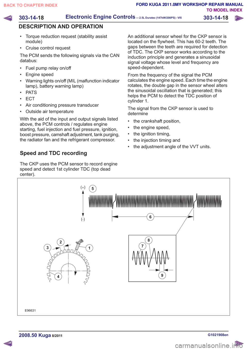
Speed and TDC recording
The CKP uses the PCM sensor to record engine
speed and detect 1st cylinder TDC (top dead
center). An additional sensor wheel for the CKP sensor is
located on the flywheel. This has 60-2 teeth. The
gaps between the teeth are required for detection
of TDC. The CKP sensor works according to the
induction principle and generates a sinusoidal
signal voltage whose level and frequency are
speed-dependent.
From the frequency of the signal the PCM
calculates the engine speed. Each time the engine
rotates, the double gap in the sensor wheel alters
the sinusoidal oscillation that is generated; this
helps the PCM to detect the TDC position of
cylinder 1.
The signal from the CKP sensor is used to
determine
• the crankshaft position,
• the engine speed,
• the ignition timing,
• the injection timing and
• the adjustment angle of the VVT units.
2
3
4
1
9
7
8
6
5
2
3
4
1
9
7
8
6
5
E96631
G1021908en2008.50 Kuga8/2011
303-14-
18
Electronic Engine Controls— 2.5L Duratec (147kW/200PS) - VI5303-14-
18
DESCRIPTION AND OPERATION
TO MODEL INDEX
BACK TO CHAPTER INDEX
FORD KUGA 2011.0MY WORKSHOP REPAIR MANUAL
Page 1866 of 2057

Output signals
Hard wired
• Item 8: PCM– Start inhibitor. Supplies the PCM with a signalthat indicates whether the engine can be
started or not.
• Item 9: Selector lever module (select-shift module)
– Controls the solenoid switch in the selectorlever unit.
• Position 10: PWM solenoid valve – shift pressure (SLS)
– Matches the line pressure to a shift pressureand is activated for certain gears.
• Position 11: PWM solenoid valve – main line pressure (SLT)
– Adjusts the linear line pressure for gearchanges without jolts.
• Position 12: PWM- solenoid valve – TCC (SLU) – Matches the line pressure to a torqueconverter lock-up pressure. Is also used for
certain gearshifts.
• Items 13 - 17: Shift solenoids S1 – S5 – The TCM checks which gear is engaged asthe solenoids become active in different
patterns.
Via the LIN data bus
• Item 7: Selector lever module (select-shift module)
– The TCM transmits a signal to the selectorlever module which activates the LED (light
emitting diode) in the selector mechanism
assembly according to the selector lever
position. Via the CAN data bus
• Item 2: GEM
– The selector lever module transmits a signalvia the TCM, which indicates that the selector
lever is locked in position P. The GEM uses
this information to control the ignition switch
key inhibit function.
– The TCM transmits a signal via the GEM to activate the back-up lamps.
• Item 3: Instrument Cluster – Current selector lever position. Used toindicate the selector lever position in the
instrument cluster.
– Check the warning lamps via the GEM. In the event of a fault, the general warning lamp
lights.
– Text messages in the instrument cluster via the GEM. The driver receives various
malfunction messages from the TCM.
– The TCM transmits signals on the CAN data bus to the PCM so that the MIL lights up in
the event of emissions-related faults.
• Item 4: PCM – Transmission fluid temperature, used tocompensate for increased loads at low fluid
temperatures.
– Gear selected, used by the engine so that it can compensate for different loads.
– Torque converter lockup, used by the engine so that it can compensate for different loads.
– Next gear planned by the TCM, used by the engine to compensate for different loads.
– Requirement for a reduced engine torque during gear shifts, the engine reduces the
engine torque during gear shifts.
– Torque limiting requirement, the engine limits the engine torque according to the gear
engaged.
• Item 5: ABS module – Current gear, used to transmit a signal, notfor shift control.
– Vehicle speed, used as reserve.
Control valve assembly
G1163605en2008.50 Kuga8/2011
307-01- 45
Automatic Transmission/Transaxle
— Vehicles With:
5-Speed Automatic Transaxle - AW55 AWD
307-01- 45
DESCRIPTION AND OPERATION
TO MODEL INDEX
BACK TO CHAPTER INDEX
FORD KUGA 2011.0MY WORKSHOP REPAIR MANUAL
Page:
< prev 1-8 9-16 17-24