Page 1866 of 2057

Output signals
Hard wired
• Item 8: PCM– Start inhibitor. Supplies the PCM with a signalthat indicates whether the engine can be
started or not.
• Item 9: Selector lever module (select-shift module)
– Controls the solenoid switch in the selectorlever unit.
• Position 10: PWM solenoid valve – shift pressure (SLS)
– Matches the line pressure to a shift pressureand is activated for certain gears.
• Position 11: PWM solenoid valve – main line pressure (SLT)
– Adjusts the linear line pressure for gearchanges without jolts.
• Position 12: PWM- solenoid valve – TCC (SLU) – Matches the line pressure to a torqueconverter lock-up pressure. Is also used for
certain gearshifts.
• Items 13 - 17: Shift solenoids S1 – S5 – The TCM checks which gear is engaged asthe solenoids become active in different
patterns.
Via the LIN data bus
• Item 7: Selector lever module (select-shift module)
– The TCM transmits a signal to the selectorlever module which activates the LED (light
emitting diode) in the selector mechanism
assembly according to the selector lever
position. Via the CAN data bus
• Item 2: GEM
– The selector lever module transmits a signalvia the TCM, which indicates that the selector
lever is locked in position P. The GEM uses
this information to control the ignition switch
key inhibit function.
– The TCM transmits a signal via the GEM to activate the back-up lamps.
• Item 3: Instrument Cluster – Current selector lever position. Used toindicate the selector lever position in the
instrument cluster.
– Check the warning lamps via the GEM. In the event of a fault, the general warning lamp
lights.
– Text messages in the instrument cluster via the GEM. The driver receives various
malfunction messages from the TCM.
– The TCM transmits signals on the CAN data bus to the PCM so that the MIL lights up in
the event of emissions-related faults.
• Item 4: PCM – Transmission fluid temperature, used tocompensate for increased loads at low fluid
temperatures.
– Gear selected, used by the engine so that it can compensate for different loads.
– Torque converter lockup, used by the engine so that it can compensate for different loads.
– Next gear planned by the TCM, used by the engine to compensate for different loads.
– Requirement for a reduced engine torque during gear shifts, the engine reduces the
engine torque during gear shifts.
– Torque limiting requirement, the engine limits the engine torque according to the gear
engaged.
• Item 5: ABS module – Current gear, used to transmit a signal, notfor shift control.
– Vehicle speed, used as reserve.
Control valve assembly
G1163605en2008.50 Kuga8/2011
307-01- 45
Automatic Transmission/Transaxle
— Vehicles With:
5-Speed Automatic Transaxle - AW55 AWD
307-01- 45
DESCRIPTION AND OPERATION
TO MODEL INDEX
BACK TO CHAPTER INDEX
FORD KUGA 2011.0MY WORKSHOP REPAIR MANUAL
Page 1882 of 2057

Transmission Fluid Level Check
General EquipmentFord Diagnostic Equipment
Materials
Specification
Name
WSS-M2C924-A / 4U7J-
M2C924-AA
Automatic Transmission
Oil E-AW
Inspection
1.
Refer to: Health and Safety Precautions (100-00
General Information, Description and
Operation).
2. Connect the Ford diagnostic equipment.
General Equipment: Ford Diagnostic Equipment
3. Make sure that the transmission is not in
emergency operation mode.
4. Make sure that the transmission fluid
temperature is between 70° and 80°C.
General Equipment: Ford Diagnostic Equipment
80
70
E114667
5. WARNING: Make sure that the brake pedal and parking brake are fully applied
during the test.
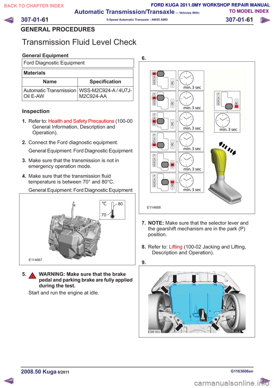
Start and run the engine at idle. 6.
E114668
7. NOTE:
Make sure that the selector lever and
the gearshift mechanism are in the park (P)
position.
8. Refer to: Lifting(100-02 Jacking and Lifting,
Description and Operation).
9.
E98183
G1163606en2008.50 Kuga8/2011
307-01- 61
Automatic Transmission/Transaxle
— Vehicles With:
5-Speed Automatic Transaxle - AW55 AWD
307-01- 61
GENERAL PROCEDURES
TO MODEL INDEX
BACK TO CHAPTER INDEX
FORD KUGA 2011.0MY WORKSHOP REPAIR MANUAL
Page 1887 of 2057
40.Refer to: Transmission Fluid Level Check
(307-01 Automatic Transmission/Transaxle -
Vehicles With: 5-Speed Automatic Transaxle
- AW55 AWD, General Procedures).
G1163607en2008.50 Kuga8/2011
307-01- 66
Automatic Transmission/Transaxle
— Vehicles With:
5-Speed Automatic Transaxle - AW55 AWD
307-01- 66
GENERAL PROCEDURES
TO MODEL INDEX
BACK TO CHAPTER INDEX
FORD KUGA 2011.0MY WORKSHOP REPAIR MANUAL
Page 1888 of 2057
Halfshaft Seal LH
Special Tool(s)303-293
Remover, Crankshaft Seal
21143
Special Tool(s)308-203
Installer, Differential Double
Lip Seal
16066
Removal
1.Refer to: Health and Safety Precautions (100-00
General Information, Description and
Operation).
2. Refer to: Front Halfshaft LH (205-04 Front Drive
Halfshafts, Removal and Installation).
3. Special Tool(s): 303-293
303-293303-293
E114366
Installation
1.Special Tool(s): 308-203
308-203308-203
E114367
2.Refer to: Front Halfshaft LH (205-04 Front Drive
Halfshafts, Removal and Installation).
3. Refer to: Transmission Fluid Level Check
(307-01 Automatic Transmission/Transaxle -
Vehicles With: 5-Speed Automatic Transaxle
- AW55 AWD, General Procedures).
G1163610en2008.50 Kuga8/2011
307-01- 67
Automatic Transmission/Transaxle
— Vehicles With:
5-Speed Automatic Transaxle - AW55 AWD
307-01- 67
REMOVAL AND INSTALLATION
TO MODEL INDEX
BACK TO CHAPTER INDEX
FORD KUGA 2011.0MY WORKSHOP REPAIR MANUAL
Page 1889 of 2057

Halfshaft Seal RH
Special Tool(s) / General Equipment308-784
Installer, Halfshaft Seal
E115803
Special Tool(s) / General EquipmentFlat-bladed screwdriver
Removal
1. Refer to: Health and Safety Precautions (100-00
General Information, Description and
Operation).
2. Refer to: Transfer Case (307-07 Transfer Case
- Vehicles With: 5-Speed Automatic Transaxle
- AW55 AWD/6-Speed Automatic Transaxle
- 6DCT450, Removal).
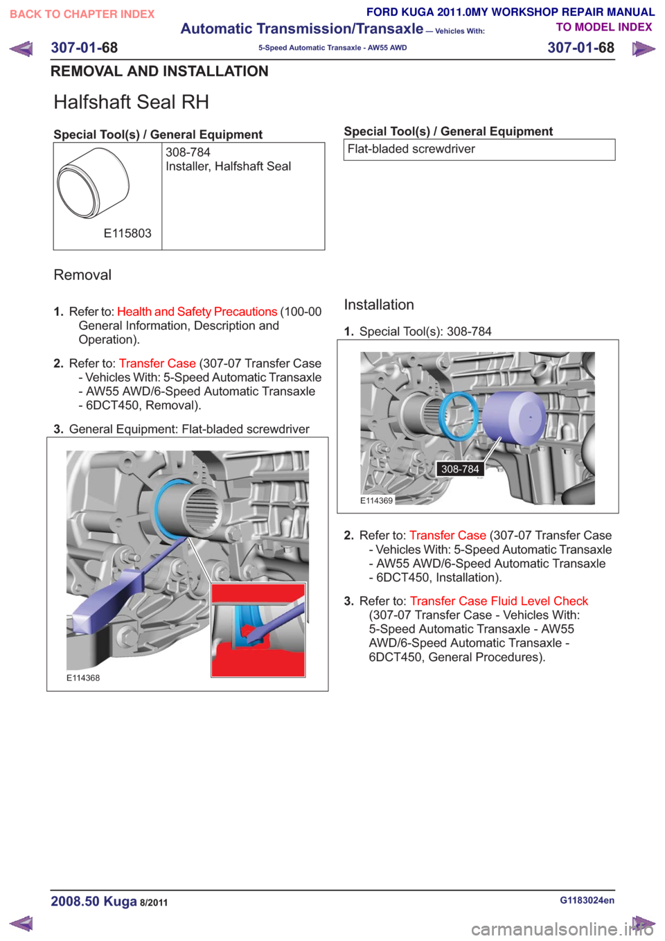
3. General Equipment: Flat-bladed screwdriver
E114368
Installation
1.Special Tool(s): 308-784
308-784308-784
E114369
2.Refer to: Transfer Case (307-07 Transfer Case
- Vehicles With: 5-Speed Automatic Transaxle
- AW55 AWD/6-Speed Automatic Transaxle
- 6DCT450, Installation).
3. Refer to: Transfer Case Fluid Level Check
(307-07 Transfer Case - Vehicles With:
5-Speed Automatic Transaxle - AW55
AWD/6-Speed Automatic Transaxle -
6DCT450, General Procedures).
G1183024en2008.50 Kuga8/2011
307-01- 68
Automatic Transmission/Transaxle
— Vehicles With:
5-Speed Automatic Transaxle - AW55 AWD
307-01- 68
REMOVAL AND INSTALLATION
TO MODEL INDEX
BACK TO CHAPTER INDEX
FORD KUGA 2011.0MY WORKSHOP REPAIR MANUAL
Page 1921 of 2057
40.Torque: 10Nm
E101006
41.Refer to: Battery(414-01 Battery, Mounting and
Cables, Removal and Installation).
42. On both sides.
Torque: 35
Nm
E99147
x3
43.Refer to: Air Cleaner (303-12 Intake Air
Distribution and Filtering - 2.5L Duratec
(147kW/200PS) - VI5, Removal and
Installation).
44.
E114689
45. Refer to: Cowl Panel Grille (501-02 Front End
Body Panels, Removal and Installation).
Refer to: Transmission Fluid Level Check
(307-01 Automatic Transmission/Transaxle -
Vehicles With: 5-Speed Automatic Transaxle
- AW55 AWD, General Procedures).
G1163646en2008.50 Kuga8/2011
307-01- 100
Automatic Transmission/Transaxle
— Vehicles With:
5-Speed Automatic Transaxle - AW55 AWD
307-01- 100
INSTALLATION
TO MODEL INDEX
BACK TO CHAPTER INDEX
FORD KUGA 2011.0MY WORKSHOP REPAIR MANUAL
Page 1928 of 2057
3.Refer to: Transfer Case Fluid Level Check
(307-07 Transfer Case - Vehicles With:
5-Speed Automatic Transaxle - AW55
AWD/6-Speed Automatic Transaxle -
6DCT450, General Procedures).
G1163667en2008.50 Kuga8/2011
307-02- 7
Transmission/Transaxle Cooling
— Vehicles With: 5-Speed
Automatic Transaxle - AW55 AWD/6-Speed Automatic Transaxle - 6DCT450
307-02- 7
REMOVAL AND INSTALLATION
TO MODEL INDEX
BACK TO CHAPTER INDEX
FORD KUGA 2011.0MY WORKSHOP REPAIR MANUAL
Page 1930 of 2057
7.
E98184
8. CAUTION: Make sure that all openingsare sealed.
E114923
9. CAUTION: Make sure that all openingsare sealed.
E114962
Installation
1.To install, reverse the removal procedure.
2. Refer to: Transmission Fluid Level Check
(307-01 Automatic Transmission/Transaxle -
Vehicles With: 5-Speed Automatic Transaxle
- AW55 AWD, General Procedures).
G1163668en2008.50 Kuga8/2011
307-02- 9
Transmission/Transaxle Cooling
— Vehicles With: 5-Speed
Automatic Transaxle - AW55 AWD/6-Speed Automatic Transaxle - 6DCT450
307-02- 9
REMOVAL AND INSTALLATION
TO MODEL INDEX
BACK TO CHAPTER INDEX
FORD KUGA 2011.0MY WORKSHOP REPAIR MANUAL