Page 1461 of 2057

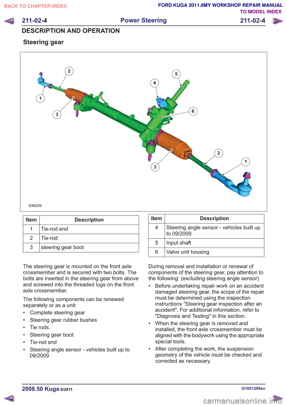
Steering gear
E96209
1
2
3
4
5
1
2
63
Description
Item
Tie-rod end
1
Tie-rod
2
steering gear boot
3Description
Item
Steering angle sensor - vehicles built up
to 09/2009
4
Input shaft
5
Valve unit housing
6
The steering gear is mounted on the front axle
crossmember and is secured with two bolts. The
bolts are inserted in the steering gear from above
and screwed into the threaded lugs on the front
axle crossmember.
The following components can be renewed
separately or as a unit:
• Complete steering gear
• Steering gear rubber bushes
• Tie rods.
• Steering gear boot
• Tie-rod end
• Steering angle sensor - vehicles built up to 09/2009 During removal and installation or renewal of
components of the steering gear, pay attention to
the following: (excluding steering angle sensor)
• Before undertaking repair work on an accident
damaged steering gear, the scope of the repair
must be determined using the inspection
instructions "Steering gear inspection after an
accident". For additional information, refer to
"Diagnosis and Testing" in this section.
• When the steering gear is removed and installed, the front axle crossmember must be
aligned with the bodywork using the appropriate
special tools.
• After completing the work, the suspension geometry of the vehicle must be checked and
corrected as necessary.
G1001269en2008.50 Kuga8/2011
211-02- 4
Power Steering
211-02- 4
DESCRIPTION AND OPERATION
TO MODEL INDEX
BACK TO CHAPTER INDEX
FORD KUGA 2011.0MY WORKSHOP REPAIR MANUAL
Page 1504 of 2057

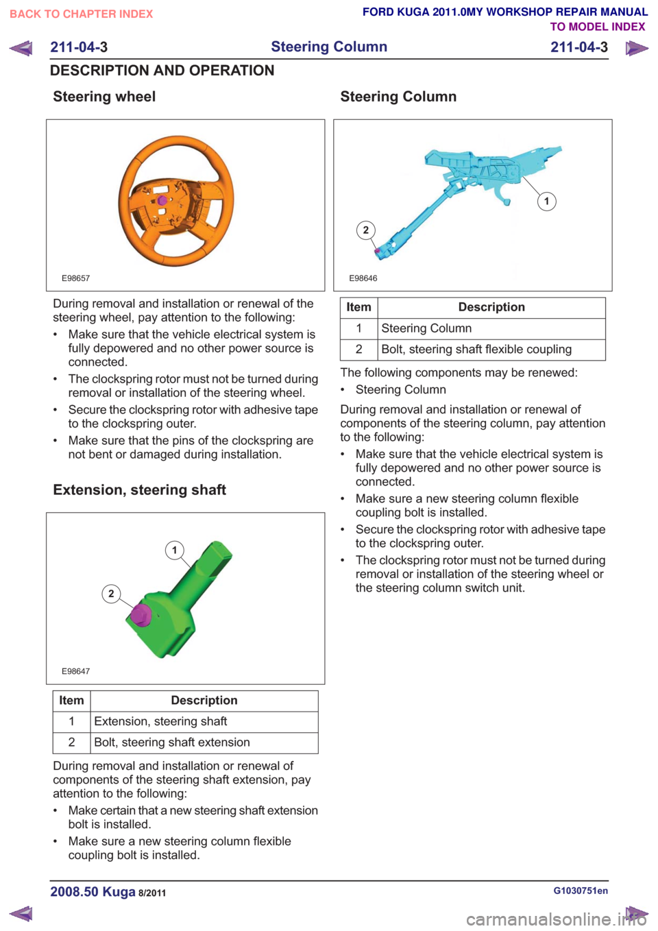
Steering wheel
E98657
During removal and installation or renewal of the
steering wheel, pay attention to the following:
• Make sure that the vehicle electrical system isfully depowered and no other power source is
connected.
• The clockspring rotor must not be turned during removal or installation of the steering wheel.
• Secure the clockspring rotor with adhesive tape to the clockspring outer.
• Make sure that the pins of the clockspring are not bent or damaged during installation.
Extension, steering shaft
E98647
1
2
Description
Item
Extension, steering shaft
1
Bolt, steering shaft extension
2
During removal and installation or renewal of
components of the steering shaft extension, pay
attention to the following:
• Make certain that a new steering shaft extension bolt is installed.
• Make sure a new steering column flexible coupling bolt is installed.
Steering Column
E98646
1
2
Description
Item
Steering Column
1
Bolt, steering shaft flexible coupling
2
The following components may be renewed:
• Steering Column
During removal and installation or renewal of
components of the steering column, pay attention
to the following:
• Make sure that the vehicle electrical system is fully depowered and no other power source is
connected.
• Make sure a new steering column flexible coupling bolt is installed.
• Secure the clockspring rotor with adhesive tape to the clockspring outer.
• The clockspring rotor must not be turned during removal or installation of the steering wheel or
the steering column switch unit.
G1030751en2008.50 Kuga8/2011
211-04- 3
Steering Column
211-04- 3
DESCRIPTION AND OPERATION
TO MODEL INDEX
BACK TO CHAPTER INDEX
FORD KUGA 2011.0MY WORKSHOP REPAIR MANUAL
Page 1511 of 2057

Steering Column Switches – Overview
Switch unit, steering column
E98629
1
2
3
4
5
Description
Item
Left-hand switch, steering column
1
Switch unit carrier, steering column
2
Right-hand switch, steering column
3Description
Item
Steering wheel rotation sensor
Refer to: Anti-Lock Control - Stability
Assist (206-09 Anti-Lock Control -
Stability Assist, Description and
Operation).
4
Clockspring
5
Clockspring
The clockspring is designed to carry signals
between the RCM and the driver air bag module.
The clockspring is installed on the steering column,
and consists of fixed and moving parts connected
by a coiled Mylar tape with internal conducting
tracks. The Mylar tape is able to 'wind up' and
'unwind' as the steering wheel is rotated,
maintaining electrical contact at all times between
the RCM and the driver air bag module. During removal and installation or renewal of the
clockspring, pay attention to the following:
• Before installation of the clockspring, it must be
aligned according to the installation instructions.
• Make sure that the vehicle electrical system is fully depowered and no other power source is
connected.
• Secure the clockspring rotor with adhesive tape to the clockspring outer.
• The clockspring rotor must not be turned during removal or installation of the steering wheel or
the steering column switch unit.
G1030755en2008.50 Kuga8/2011
211-05- 3
Steering Column Switches
211-05- 3
DESCRIPTION AND OPERATION
TO MODEL INDEX
BACK TO CHAPTER INDEX
FORD KUGA 2011.0MY WORKSHOP REPAIR MANUAL
Page 1595 of 2057
Vehicles with PCM security shield
14.
x4x4
E92343
Vehicles without PCM security shield
15.
E93509
16.
E65856
All vehicles
17.
E63326
11
2
18. CAUTION: Make sure that nocomponents catch.
Remove the following items:
• General Equipment: Retaining Strap
19. N O T E : Only tighten the bolts finger tight at this
stage.
G1191240en2008.50 Kuga8/2011
303-01- 62
Engine— 2.5L Duratec (147kW/200PS) - VI5303-01-
62
REMOVAL
TO MODEL INDEX
BACK TO CHAPTER INDEX
FORD KUGA 2011.0MY WORKSHOP REPAIR MANUAL
Page 1608 of 2057
E112535
1
2
62.General Equipment: Cable Ties
E112536
63. WARNING: Make sure that the engine
and transmission assembly is on
wooden blocks and secured with
suitable retaining straps.
General Equipment: Retaining Strap
General Equipment: Mounting Table Set
General Equipment: Wooden Block
G1191240en2008.50 Kuga8/2011
303-01- 75
Engine— 2.5L Duratec (147kW/200PS) - VI5303-01-
75
REMOVAL
TO MODEL INDEX
BACK TO CHAPTER INDEX
FORD KUGA 2011.0MY WORKSHOP REPAIR MANUAL
Page 1653 of 2057
4.Torque: 48Nm
E65770
5. NOTE: Install all the bolts finger tight before
final tightening.
Torque: 60
Nm
6
5
3
4
2
1
x6
6
5
3
4
2
1
x6
E124910
6. WARNING: Make sure that the engine and transmission assembly is on
wooden blocks and secured with
suitable retaining straps.
General Equipment: Retaining Strap
General Equipment: Mounting Table Set
General Equipment: Wooden Block
G1191241en2008.50 Kuga8/2011
303-01- 120
Engine— 2.5L Duratec (147kW/200PS) - VI5303-01-
120
INSTALLATION
TO MODEL INDEX
BACK TO CHAPTER INDEX
FORD KUGA 2011.0MY WORKSHOP REPAIR MANUAL
Page 1667 of 2057
49. CAUTION: Make sure that nocomponents catch.
General Equipment: Retaining Strap
General Equipment: Trolley Jack
E112303
15 mm
50.
E112649
Vehicles without PCM security shield
51.
E112653
52.Torque: 7Nm
E93509
G1191241en2008.50 Kuga8/2011
303-01- 134
Engine— 2.5L Duratec (147kW/200PS) - VI5303-01-
134
INSTALLATION
TO MODEL INDEX
BACK TO CHAPTER INDEX
FORD KUGA 2011.0MY WORKSHOP REPAIR MANUAL
Page 1668 of 2057
Vehicles with PCM security shield
53.Torque: 7Nm
x4x4
E92343
All vehicles
54. CAUTION: Make sure that no
components catch.
Remove the following items:
• General Equipment: Retaining Strap
55. N O T E : Only tighten the bolts finger tight at this
stage. Remove the following items:
• General Equipment: Trolley Jack
E116626
56. CAUTION: Make sure that the inside of the pipe ends are clean and free of oil
residue.
1. Torque: 4Nm
2. Torque: 10Nm
E116646
1
2
2
G1191241en2008.50 Kuga8/2011
303-01- 135
Engine— 2.5L Duratec (147kW/200PS) - VI5303-01-
135
INSTALLATION
TO MODEL INDEX
BACK TO CHAPTER INDEX
FORD KUGA 2011.0MY WORKSHOP REPAIR MANUAL