Page 1944 of 2057
Capacities
Litres0.45
Transmission Fluid 8U7J-19G518-BA
G1164984en2008.50 Kuga8/2011
307-07- 2
Transfer Case
— Vehicles With: 5-Speed Automatic Transaxle - AW55
AWD/6-Speed Automatic Transaxle - 6DCT450
307-07- 2
SPECIFICATIONS
TO MODEL INDEX
BACK TO CHAPTER INDEX
FORD KUGA 2011.0MY WORKSHOP REPAIR MANUAL
Page 1951 of 2057
Transfer Case Fluid Level Check
MaterialsSpecification
Name
8U7J-19G518-BA
Rear Axle Oil SAE 75W-
90
Inspection
1. Refer to: Health and Safety Precautions (100-00
General Information, Description and
Operation).
2.
E139436
3. Material: Rear Axle Oil SAE 75W-90
(8U7J-19G518-BA) transmission fluid
•
• Correct the rear axle oil level if neccessary.
• 20ml~1mm
0mm0mm
E114595
4. NOTE:
Make sure that a new component is
installed.
Torque: 34
Nm
E139434
G1164988en2008.50 Kuga8/2011
307-07- 9
Transfer Case
— Vehicles With: 5-Speed Automatic Transaxle - AW55
AWD/6-Speed Automatic Transaxle - 6DCT450
307-07- 9
GENERAL PROCEDURES
TO MODEL INDEX
BACK TO CHAPTER INDEX
FORD KUGA 2011.0MY WORKSHOP REPAIR MANUAL
Page 1954 of 2057
3.Special Tool(s): 308-785
308-785
60
308-785
60
E115600
4.
E115601
5.Special Tool(s): 308-784
308-784308-784
E114369
6.Refer to: Transfer Case (307-07 Transfer Case
- Vehicles With: 5-Speed Automatic Transaxle
- AW55 AWD/6-Speed Automatic Transaxle
- 6DCT450, Installation).
7. Refer to: Transfer Case Fluid Level Check
(307-07 Transfer Case - Vehicles With:
5-Speed Automatic Transaxle - AW55
AWD/6-Speed Automatic Transaxle -
6DCT450, General Procedures).
G1164990en2008.50 Kuga8/2011
307-07- 12
Transfer Case
— Vehicles With: 5-Speed Automatic Transaxle - AW55
AWD/6-Speed Automatic Transaxle - 6DCT450
307-07- 12
REMOVAL AND INSTALLATION
TO MODEL INDEX
BACK TO CHAPTER INDEX
FORD KUGA 2011.0MY WORKSHOP REPAIR MANUAL
Page 1958 of 2057

1.Refer to: Health and Safety Precautions (100-00
General Information, Description and
Operation).
Refer to: Transfer Case (307-07 Transfer Case
- Vehicles With: 5-Speed Automatic Transaxle
- AW55 AWD/6-Speed Automatic Transaxle
- 6DCT450, Removal).
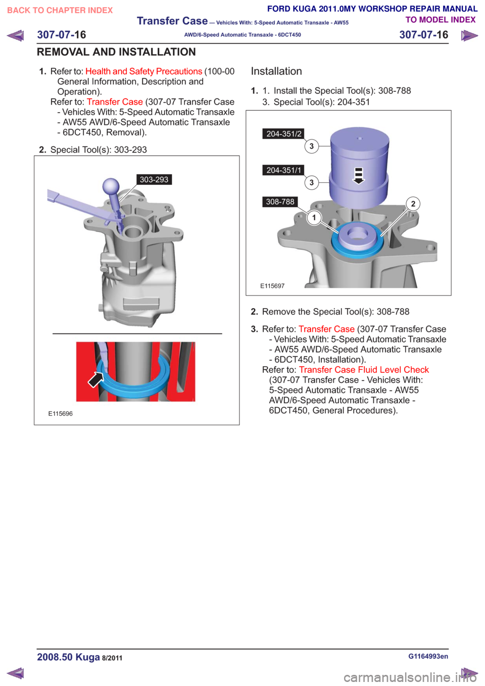
2. Special Tool(s): 303-293
303-293303-293
E115696
Installation
1. Install the Special Tool(s): 308-788
1.
3. Special Tool(s): 204-351
2308-788
1
204-351/1
3
204-351/2
3
2308-788
1
204-351/1
3
204-351/2
3
E115697
2. Remove the Special Tool(s): 308-788
3. Refer to: Transfer Case (307-07 Transfer Case
- Vehicles With: 5-Speed Automatic Transaxle
- AW55 AWD/6-Speed Automatic Transaxle
- 6DCT450, Installation).
Refer to: Transfer Case Fluid Level Check
(307-07 Transfer Case - Vehicles With:
5-Speed Automatic Transaxle - AW55
AWD/6-Speed Automatic Transaxle -
6DCT450, General Procedures).
G1164993en2008.50 Kuga8/2011
307-07- 16
Transfer Case
— Vehicles With: 5-Speed Automatic Transaxle - AW55
AWD/6-Speed Automatic Transaxle - 6DCT450
307-07- 16
REMOVAL AND INSTALLATION
TO MODEL INDEX
BACK TO CHAPTER INDEX
FORD KUGA 2011.0MY WORKSHOP REPAIR MANUAL
Page 1970 of 2057

Fuel System — Vehicles With: Fuel Additive Tank
General EquipmentFord diagnostic equipment
Principles of Operation
WARNINGS:
This procedure involves fuel additive
handling. Be prepared for fuel additive
spillage at all times and always observe
fuel handling precautions. Failure to follow
these instructions may result in personal
injury.
Eye, hand, ear protection and protective
clothing are required to be worn during
any general service or removal and
installation service procedure of fuel
additive system components. Failure to
follow this instruction may result in
personal injury.
In case of fuel additive fluid contact with
the skin or the eyes, flush immediately with
water for a minimum of 15 minutes and
seek prompt medical attention. Failure to
follow these instructions may result in
personal injury.
If fuel additive fluid is swallowed, call a
physician immediately. Rinse mouth
immediately with water, do not induce
vomiting. Failure to follow these
instructions may result in personal injury.
Always provide adequate ventilation when
working on the fuel additive fluid system
or related components. Failure to follow
these instructions may result in personal
injury.
Do not smoke or carry lighted tobacco or
open flame of any type when working on
or near any fuel related components.
Highly flammable vapors are always
present and may ignite. Failure to follow
these instructions may result in personal
injury.
CAUTION: Make sure the workshop area
in which the vehicle is being worked on is
as clean and as dust free as possible.
Foreign matter from working on clutches,
brakes or from machining or welding
operations can contaminate the fuel
system and may result in later malfunction. The fuel additive system is an on-board system
that allows the injection of an additive at each
refueling operation by the customer. The additive
quantity is proportional to the fuel quantity that has
been added. The fuel additive system module
controls the amount of additive fluid entering the
fuel tank at each refueling, A switch mounted on
the fuel filler flap is used to detect the start of the
refueling event and the fuel gauge that is mounted
within the fuel tank informs the fuel additive tank
module the quantity of actual fuel added.
Inspection and Verification
1. Verify the customer concern.
2. Visually inspect for obvious signs of leakage
and mechanical or electrical damage.
Visual Inspection Chart
Electrical
Mechanical
– Fuse(s)
– Fuel filler switch andmagnet
– Wiring harness(s)
– Electrical connector(s)
– Fuel additive system module
– Fuel additive tank module
– Instrument cluster
– Powertrain Control Module (PCM)
– Fuel level sensor
– Fuel additive tank
– Fuel additive tank
line(s)
– Fuel additive tank pipe(s)
– Fuel additive tank connector(s)
– Fuel tank filler cap
3. If an obvious cause for an observed or reported concern is found, correct the cause (if possible)
before proceeding to the next step
4. If the cause is not visually evident, REFER to the Ford diagnostic equipment.
G1080718en2008.50 Kuga8/2011
310-00- 2
Fuel System - General Information
310-00- 2
DIAGNOSIS AND TESTING
TO MODEL INDEX
BACK TO CHAPTER INDEX
FORD KUGA 2011.0MY WORKSHOP REPAIR MANUAL
Page 1979 of 2057

Fuel Tank Draining
General EquipmentFluid Container
Fuel Tank Draining Equipment
Hose Clamp Remover/Installer
Activation
CAUTION: If the fuel tank has been filled
with the wrong type of fuel, the engine
must not be started.
NOTE: Removal steps in this procedure may
contain installation details.
6. Refer to: Petrol and Petrol-Ethanol Fuel
Systems Health and Safety Precautions
(100-00 General Information, Description and
Operation).
7. Refer to: Lifting(100-02 Jacking and Lifting,
Description and Operation).
8. WARNINGS:
Fuel may still be present in the fuel tank
after draining.
Be prepared to collect escaping fluids.
CAUTION: Use suitable paper to absorb
any escaping fluid. NOTE:
Make sure that a new component is
installed.
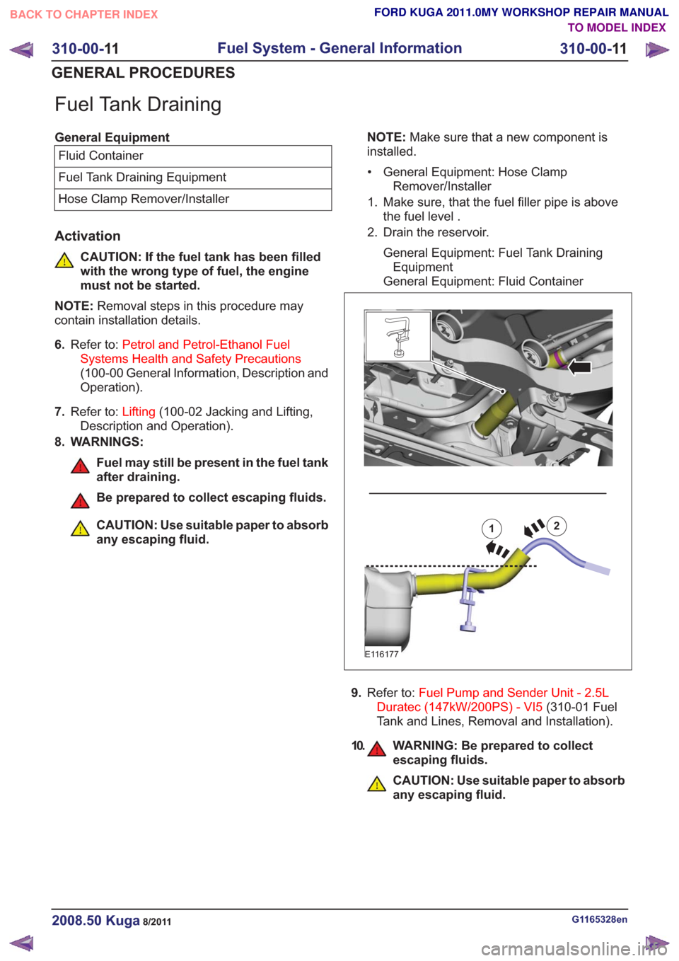
• General Equipment: Hose Clamp Remover/Installer
1. Make sure, that the fuel filler pipe is above the fuel level .
2. Drain the reservoir.
General Equipment: Fuel Tank DrainingEquipment
General Equipment: Fluid Container12
E116177
9. Refer to: Fuel Pump and Sender Unit - 2.5L
Duratec (147kW/200PS) - VI5 (310-01 Fuel
Tank and Lines, Removal and Installation).
10. WARNING: Be prepared to collect escaping fluids.
CAUTION: Use suitable paper to absorb
any escaping fluid.
G1165328en2008.50 Kuga8/2011
310-00- 11
Fuel System - General Information
310-00- 11
GENERAL PROCEDURES
TO MODEL INDEX
BACK TO CHAPTER INDEX
FORD KUGA 2011.0MY WORKSHOP REPAIR MANUAL
Page 1980 of 2057
Drain the reservoir.
General Equipment: Fluid Container
E114482
11 .Drain the reservoir.
General Equipment: Fuel Tank Draining
Equipment
General Equipment: Fluid Container
E114435
G1165328en2008.50 Kuga8/2011
310-00- 12
Fuel System - General Information
310-00- 12
GENERAL PROCEDURES
TO MODEL INDEX
BACK TO CHAPTER INDEX
FORD KUGA 2011.0MY WORKSHOP REPAIR MANUAL
Page 1989 of 2057
7.Torque: 15Nm
x4x4
E104227
8.Refer to: Fuel Tank Draining (310-00 Fuel
System - General Information, General
Procedures).
Vehicles with fuel fired booster heater
9.
E113924
10.
E113925
11. WARNING: Be prepared to collect escaping fluids.
CAUTION: Use suitable paper to absorb
any escaping fluid.
Refer to: Quick Release Coupling (310-00 Fuel
System - General Information, General
Procedures).
x2x2
E113944
All vehicles
12. WARNING: Be prepared to collect escaping fluids.
CAUTION: Use suitable paper to absorb
any escaping fluid.
Refer to: Quick Release Coupling (310-00 Fuel
System - General Information, General
Procedures).
E113945
13. Torque: 30Nm
x4x4
E104228
G1175018en2008.50 Kuga8/2011
310-01- 9
Fuel Tank and Lines
310-01- 9
REMOVAL AND INSTALLATION
TO MODEL INDEX
BACK TO CHAPTER INDEX
FORD KUGA 2011.0MY WORKSHOP REPAIR MANUAL