2011 FORD KUGA fuel cap
[x] Cancel search: fuel capPage 1847 of 2057

E112322
The TCM adapts the gear changing to ensure that
the correct gear is selected for the style of driving,
the engine load, driver requirements, vehicle speed
etc. This leads to lower fuel consumption together
with improved comfort through smoother gear
changes and lower noise levels.
The TCM receives information on the driver's
desired transmission range and type of driving
mode. In contrast to a transmission which is only
controlled hydraulically, the control module can
calculate the best times to shift gear and activate
torque converter lockup by using the signals from
the sensors in the transmission and the engine
management system.
The control module enables small changes in the
operating conditions to be made and adapts thevarious transmission functions to ensure that the
correct gear is always selected in relation to the
type of driving mode.
The TCM has adaptive capabilities. This ensures
smooth gear changes throughout the whole service
life of the transmission.
To exactly determine the activation points of the
gear shifts and torque converter lockup on the
basis of the type of driving mode chosen, the TCM
receives the following information:
• Transmission range chosen (TR sensor).
• Type of driving mode chosen
(normal/sport/select-shift).
• Transmission input shaft speed (TSS sensor).
• Transmission output shaft speed (OSS sensor).
• Transmission fluid temperature (TFT sensor).
• The engine speed and the torque as well as the throttle plate opening - from the PCM via the
CAN data bus.
• Actuation of the accelerator pedal - from the PCM via the CAN data bus.
• Coolant temperature - from the PCM via the CAN data bus.
• Vehicle speed - from the ABS via the CAN data bus.
• Actuation of the brake pedal - from the ABS via the CAN data bus.
Pin assignment for TCM connector 'A' (connection to vehicle)
11
E125669
Description
Item
Battery (+)
1
not assigned
2Description
Item
not assigned
3
not assigned
4
G1163605en2008.50 Kuga8/2011
307-01- 26
Automatic Transmission/Transaxle
— Vehicles With:
5-Speed Automatic Transaxle - AW55 AWD
307-01- 26
DESCRIPTION AND OPERATION
TO MODEL INDEX
BACK TO CHAPTER INDEX
FORD KUGA 2011.0MY WORKSHOP REPAIR MANUAL
Page 1849 of 2057
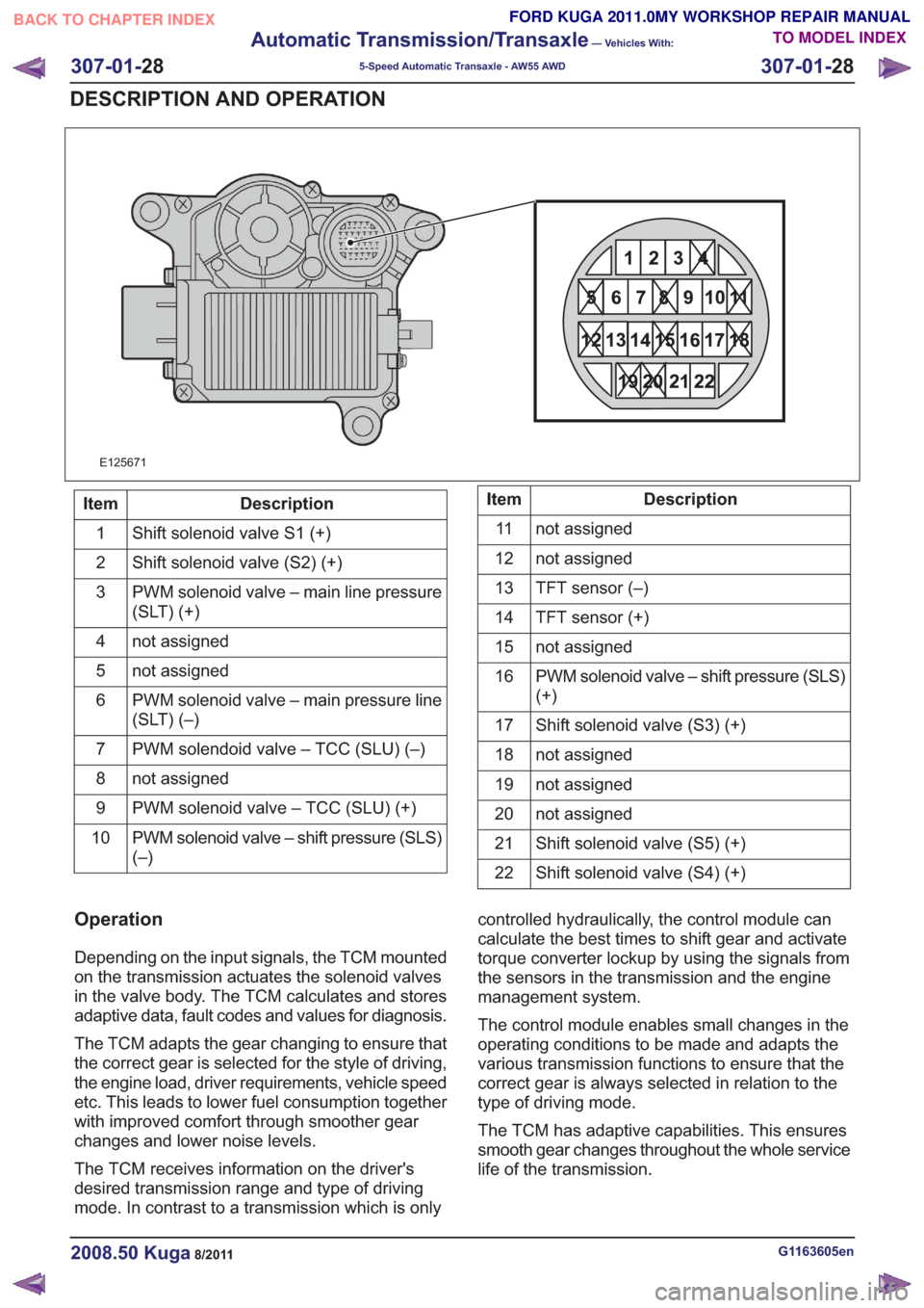
21
22 20 19
15 14 13
161718 12
876
9
10
11 5
3
42121
22 20 19
15 14 13
161718 12
876
9
10
11 5
3
421
E125671
Description
Item
Shift solenoid valve S1 (+)
1
Shift solenoid valve (S2) (+)
2
PWM solenoid valve – main line pressure
(SLT) (+)
3
not assigned
4
not assigned
5
PWM solenoid valve – main pressure line
(SLT) (–)
6
PWM solendoid valve – TCC (SLU) (–)
7
not assigned
8
PWM solenoid valve – TCC (SLU) (+)
9
PWM solenoid valve – shift pressure (SLS)
(–)
10Description
Item
not assigned
11
not assigned
12
TFT sensor (–)
13
TFT sensor (+)
14
not assigned
15
PWM solenoid valve – shift pressure (SLS)
(+)
16
Shift solenoid valve (S3) (+)
17
not assigned
18
not assigned
19
not assigned
20
Shift solenoid valve (S5) (+)
21
Shift solenoid valve (S4) (+)
22
Operation
Depending on the input signals, the TCM mounted
on the transmission actuates the solenoid valves
in the valve body. The TCM calculates and stores
adaptive data, fault codes and values for diagnosis.
The TCM adapts the gear changing to ensure that
the correct gear is selected for the style of driving,
the engine load, driver requirements, vehicle speed
etc. This leads to lower fuel consumption together
with improved comfort through smoother gear
changes and lower noise levels.
The TCM receives information on the driver's
desired transmission range and type of driving
mode. In contrast to a transmission which is only controlled hydraulically, the control module can
calculate the best times to shift gear and activate
torque converter lockup by using the signals from
the sensors in the transmission and the engine
management system.
The control module enables small changes in the
operating conditions to be made and adapts the
various transmission functions to ensure that the
correct gear is always selected in relation to the
type of driving mode.
The TCM has adaptive capabilities. This ensures
smooth gear changes throughout the whole service
life of the transmission.
G1163605en2008.50 Kuga8/2011
307-01-
28
Automatic Transmission/Transaxle
— Vehicles With:
5-Speed Automatic Transaxle - AW55 AWD
307-01- 28
DESCRIPTION AND OPERATION
TO MODEL INDEX
BACK TO CHAPTER INDEX
FORD KUGA 2011.0MY WORKSHOP REPAIR MANUAL
Page 1970 of 2057
Fuel System — Vehicles With: Fuel Additive Tank
General EquipmentFord diagnostic equipment
Principles of Operation
WARNINGS:
This procedure involves fuel additive
handling. Be prepared for fuel additive
spillage at all times and always observe
fuel handling precautions. Failure to follow
these instructions may result in personal
injury.
Eye, hand, ear protection and protective
clothing are required to be worn during
any general service or removal and
installation service procedure of fuel
additive system components. Failure to
follow this instruction may result in
personal injury.
In case of fuel additive fluid contact with
the skin or the eyes, flush immediately with
water for a minimum of 15 minutes and
seek prompt medical attention. Failure to
follow these instructions may result in
personal injury.
If fuel additive fluid is swallowed, call a
physician immediately. Rinse mouth
immediately with water, do not induce
vomiting. Failure to follow these
instructions may result in personal injury.
Always provide adequate ventilation when
working on the fuel additive fluid system
or related components. Failure to follow
these instructions may result in personal
injury.
Do not smoke or carry lighted tobacco or
open flame of any type when working on
or near any fuel related components.
Highly flammable vapors are always
present and may ignite. Failure to follow
these instructions may result in personal
injury.
CAUTION: Make sure the workshop area
in which the vehicle is being worked on is
as clean and as dust free as possible.
Foreign matter from working on clutches,
brakes or from machining or welding
operations can contaminate the fuel
system and may result in later malfunction. The fuel additive system is an on-board system
that allows the injection of an additive at each
refueling operation by the customer. The additive
quantity is proportional to the fuel quantity that has
been added. The fuel additive system module
controls the amount of additive fluid entering the
fuel tank at each refueling, A switch mounted on
the fuel filler flap is used to detect the start of the
refueling event and the fuel gauge that is mounted
within the fuel tank informs the fuel additive tank
module the quantity of actual fuel added.
Inspection and Verification
1. Verify the customer concern.
2. Visually inspect for obvious signs of leakage
and mechanical or electrical damage.
Visual Inspection Chart
Electrical
Mechanical
– Fuse(s)
– Fuel filler switch andmagnet
– Wiring harness(s)
– Electrical connector(s)
– Fuel additive system module
– Fuel additive tank module
– Instrument cluster
– Powertrain Control Module (PCM)
– Fuel level sensor
– Fuel additive tank
– Fuel additive tank
line(s)
– Fuel additive tank pipe(s)
– Fuel additive tank connector(s)
– Fuel tank filler cap
3. If an obvious cause for an observed or reported concern is found, correct the cause (if possible)
before proceeding to the next step
4. If the cause is not visually evident, REFER to the Ford diagnostic equipment.
G1080718en2008.50 Kuga8/2011
310-00- 2
Fuel System - General Information
310-00- 2
DIAGNOSIS AND TESTING
TO MODEL INDEX
BACK TO CHAPTER INDEX
FORD KUGA 2011.0MY WORKSHOP REPAIR MANUAL
Page 1979 of 2057
Fuel Tank Draining
General EquipmentFluid Container
Fuel Tank Draining Equipment
Hose Clamp Remover/Installer
Activation
CAUTION: If the fuel tank has been filled
with the wrong type of fuel, the engine
must not be started.
NOTE: Removal steps in this procedure may
contain installation details.
6. Refer to: Petrol and Petrol-Ethanol Fuel
Systems Health and Safety Precautions
(100-00 General Information, Description and
Operation).
7. Refer to: Lifting(100-02 Jacking and Lifting,
Description and Operation).
8. WARNINGS:
Fuel may still be present in the fuel tank
after draining.
Be prepared to collect escaping fluids.
CAUTION: Use suitable paper to absorb
any escaping fluid. NOTE:
Make sure that a new component is
installed.
• General Equipment: Hose Clamp Remover/Installer
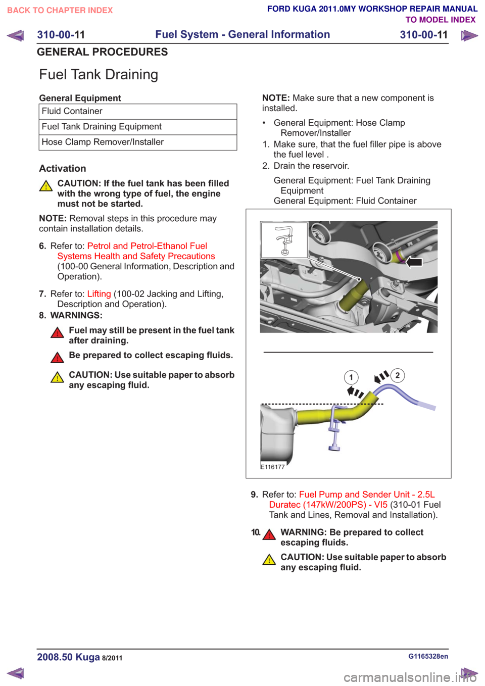
1. Make sure, that the fuel filler pipe is above the fuel level .
2. Drain the reservoir.
General Equipment: Fuel Tank DrainingEquipment
General Equipment: Fluid Container12
E116177
9. Refer to: Fuel Pump and Sender Unit - 2.5L
Duratec (147kW/200PS) - VI5 (310-01 Fuel
Tank and Lines, Removal and Installation).
10. WARNING: Be prepared to collect escaping fluids.
CAUTION: Use suitable paper to absorb
any escaping fluid.
G1165328en2008.50 Kuga8/2011
310-00- 11
Fuel System - General Information
310-00- 11
GENERAL PROCEDURES
TO MODEL INDEX
BACK TO CHAPTER INDEX
FORD KUGA 2011.0MY WORKSHOP REPAIR MANUAL
Page 1981 of 2057
SECTION 310-01 Fuel Tank and Lines
VEHICLE APPLICATION:2008.50 Kuga
PA G E
CONTENTS
DESCRIPTION AND OPERATION
310-01-2
Fuel Tank and Lines — 2.5L Duratec (147kW/200PS) - VI5 (Component Location) .........
310-01-5
Fuel Tank and Lines — 2.5L Duratec (147kW/200PS) - VI5 (Overview) ............................
310-01-5
Fuel tank ........................................................................\
.....................................................
310-01-5
Fuel pump and sender unit ........................................................................\
.........................
310-01-6
Fuel filler pipe and tank cap........................................................................\
........................
REMOVAL AND INSTALLATION 310-01-8
Fuel Tank — 2.5L Duratec (147kW/200PS) - VI5 ...............................................................
310-01-11
Fuel Level Sensor — 2.5L Duratec (147kW/200PS) - VI5 .................................................
310-01-12
Fuel Tank Filler Pipe ........................................................................\
...................................
310-01-14
Fuel Filler Nozzle Inhibitor ........................................................................\
..........................
310-01-18
Fuel Pump and Sender Unit — 2.5L Duratec (147kW/200PS) - VI5 ..................................
310-01-1
Fuel Tank and Lines
310-01- 1
.
TO MODEL INDEX
BACK TO CHAPTER INDEX
FORD KUGA 2011.0MY WORKSHOP REPAIR MANUAL
Page 1983 of 2057
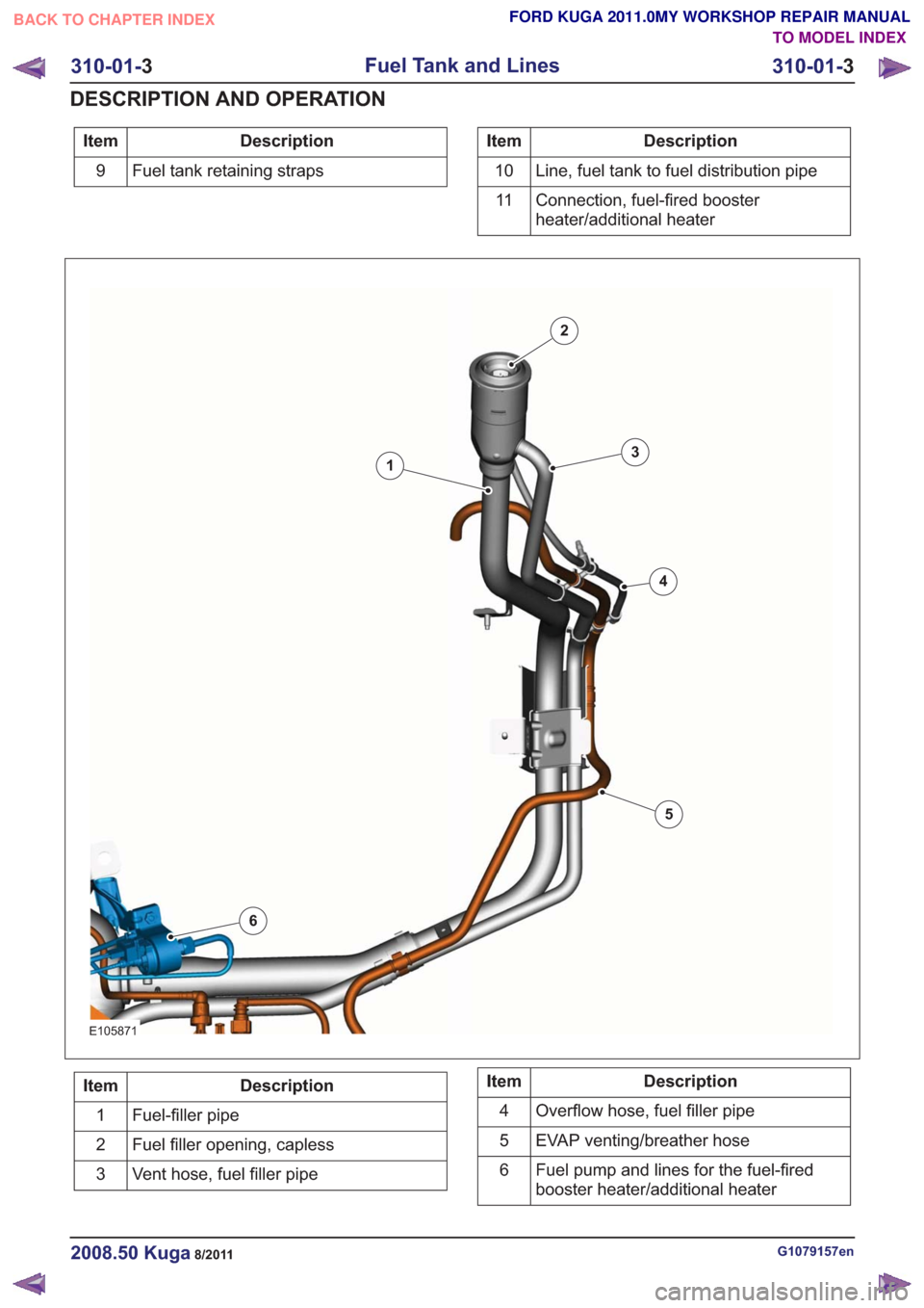
Description
Item
Fuel tank retaining straps
9Description
Item
Line, fuel tank to fuel distribution pipe
10
Connection, fuel-fired booster
heater/additional heater
11
E105871
1
2
3
4
5
6
Description
Item
Fuel-filler pipe
1
Fuel filler opening, capless
2
Vent hose, fuel filler pipe
3Description
Item
Overflow hose, fuel filler pipe
4
EVAP venting/breather hose
5
Fuel pump and lines for the fuel-fired
booster heater/additional heater
6
G1079157en2008.50 Kuga8/2011
310-01-
3
Fuel Tank and Lines
310-01- 3
DESCRIPTION AND OPERATION
TO MODEL INDEX
BACK TO CHAPTER INDEX
FORD KUGA 2011.0MY WORKSHOP REPAIR MANUAL
Page 1986 of 2057
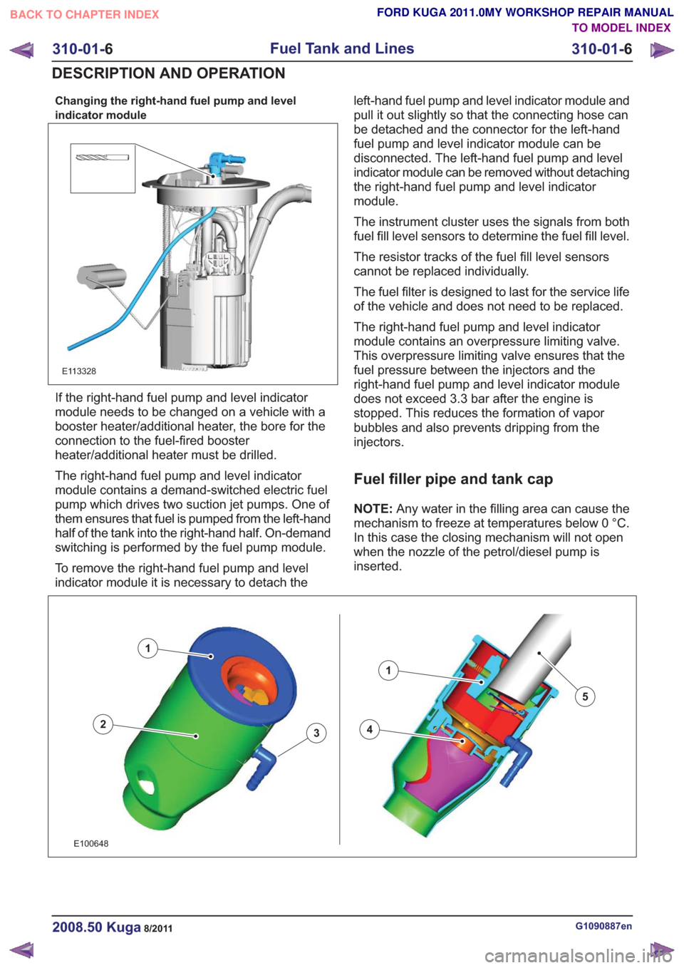
Changing the right-hand fuel pump and level
indicator module
E113328
If the right-hand fuel pump and level indicator
module needs to be changed on a vehicle with a
booster heater/additional heater, the bore for the
connection to the fuel-fired booster
heater/additional heater must be drilled.
The right-hand fuel pump and level indicator
module contains a demand-switched electric fuel
pump which drives two suction jet pumps. One of
them ensures that fuel is pumped from the left-hand
half of the tank into the right-hand half. On-demand
switching is performed by the fuel pump module.
To remove the right-hand fuel pump and level
indicator module it is necessary to detach theleft-hand fuel pump and level indicator module and
pull it out slightly so that the connecting hose can
be detached and the connector for the left-hand
fuel pump and level indicator module can be
disconnected. The left-hand fuel pump and level
indicator module can be removed without detaching
the right-hand fuel pump and level indicator
module.
The instrument cluster uses the signals from both
fuel fill level sensors to determine the fuel fill level.
The resistor tracks of the fuel fill level sensors
cannot be replaced individually.
The fuel filter is designed to last for the service life
of the vehicle and does not need to be replaced.
The right-hand fuel pump and level indicator
module contains an overpressure limiting valve.
This overpressure limiting valve ensures that the
fuel pressure between the injectors and the
right-hand fuel pump and level indicator module
does not exceed 3.3 bar after the engine is
stopped. This reduces the formation of vapor
bubbles and also prevents dripping from the
injectors.
Fuel filler pipe and tank cap
NOTE:
Any water in the filling area can cause the
mechanism to freeze at temperatures below 0 °C.
In this case the closing mechanism will not open
when the nozzle of the petrol/diesel pump is
inserted.
43
1
2
1
5
43
1
2
1
5
E100648
G1090887en2008.50 Kuga8/2011
310-01- 6
Fuel Tank and Lines
310-01- 6
DESCRIPTION AND OPERATION
TO MODEL INDEX
BACK TO CHAPTER INDEX
FORD KUGA 2011.0MY WORKSHOP REPAIR MANUAL
Page 1987 of 2057
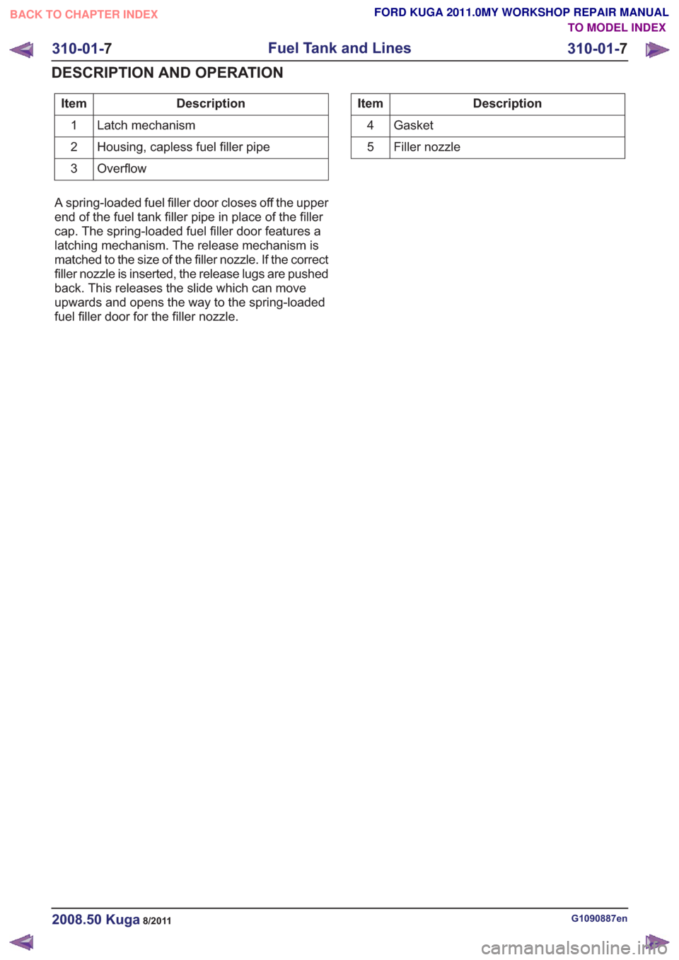
Description
Item
Latch mechanism
1
Housing, capless fuel filler pipe
2
Overflow
3Description
Item
Gasket
4
Filler nozzle
5
A spring-loaded fuel filler door closes off the upper
end of the fuel tank filler pipe in place of the filler
cap. The spring-loaded fuel filler door features a
latching mechanism. The release mechanism is
matched to the size of the filler nozzle. If the correct
filler nozzle is inserted, the release lugs are pushed
back. This releases the slide which can move
upwards and opens the way to the spring-loaded
fuel filler door for the filler nozzle.
G1090887en2008.50 Kuga8/2011
310-01- 7
Fuel Tank and Lines
310-01- 7
DESCRIPTION AND OPERATION
TO MODEL INDEX
BACK TO CHAPTER INDEX
FORD KUGA 2011.0MY WORKSHOP REPAIR MANUAL