2011 FORD KUGA engine remove
[x] Cancel search: engine removePage 107 of 2057

Blower Motor — RHD(34 374 0)
Special Tool(s)412-131
Remover/Installer, Blower
Engine
E42948
Removal
NOTE:Removal steps in this procedure may
contain installation details.
1. Refer to: Cowl Panel Grille (501-02 Front End
Body Panels, Removal and Installation).
2. Torque: 25
Nm
E101389
3.Refer to: Steering Column (211-04 Steering
Column, Removal and Installation).
4. Refer to: Floor Console Extension - Vehicles
With: Center Armrest (501-12 Instrument
Panel and Console, Removal and Installation).
5.
E102293
6. Torque: 25Nm
G1065500en2008.50 Kuga8/2011
412-01- 37
Climate Control
412-01- 37
REMOVAL AND INSTALLATION
TO MODEL INDEX
BACK TO CHAPTER INDEX
FORD KUGA 2011.0MY WORKSHOP REPAIR MANUAL
Page 170 of 2057
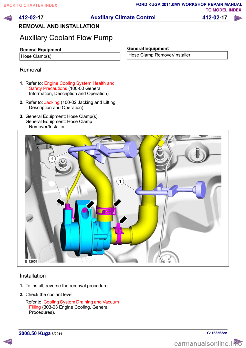
Auxiliary Coolant Flow Pump
General Equipment
Hose Clamp(s) General Equipment
Hose Clamp Remover/Installer
Removal
1. Refer to: Engine Cooling System Health and
Safety Precautions (100-00 General
Information, Description and Operation).
2. Refer to: Jacking(100-02 Jacking and Lifting,
Description and Operation).
3. General Equipment: Hose Clamp(s)
General Equipment: Hose Clamp
Remover/Installer Installation
1.
To install, reverse the removal procedure.
2. Check the coolant level.
Refer to: Cooling System Draining and Vacuum
Filling (303-03 Engine Cooling, General
Procedures). G1163562en
2008.50 Kuga 8/2011 412-02-17
Auxiliary Climate Control
412-02-17
REMOVAL AND INSTALLATIONTO MODEL INDEX
BACK TO CHAPTER INDEX
FORD KUGA 2011.0MY WORKSHOP REPAIR MANUAL11E112651
Page 174 of 2057
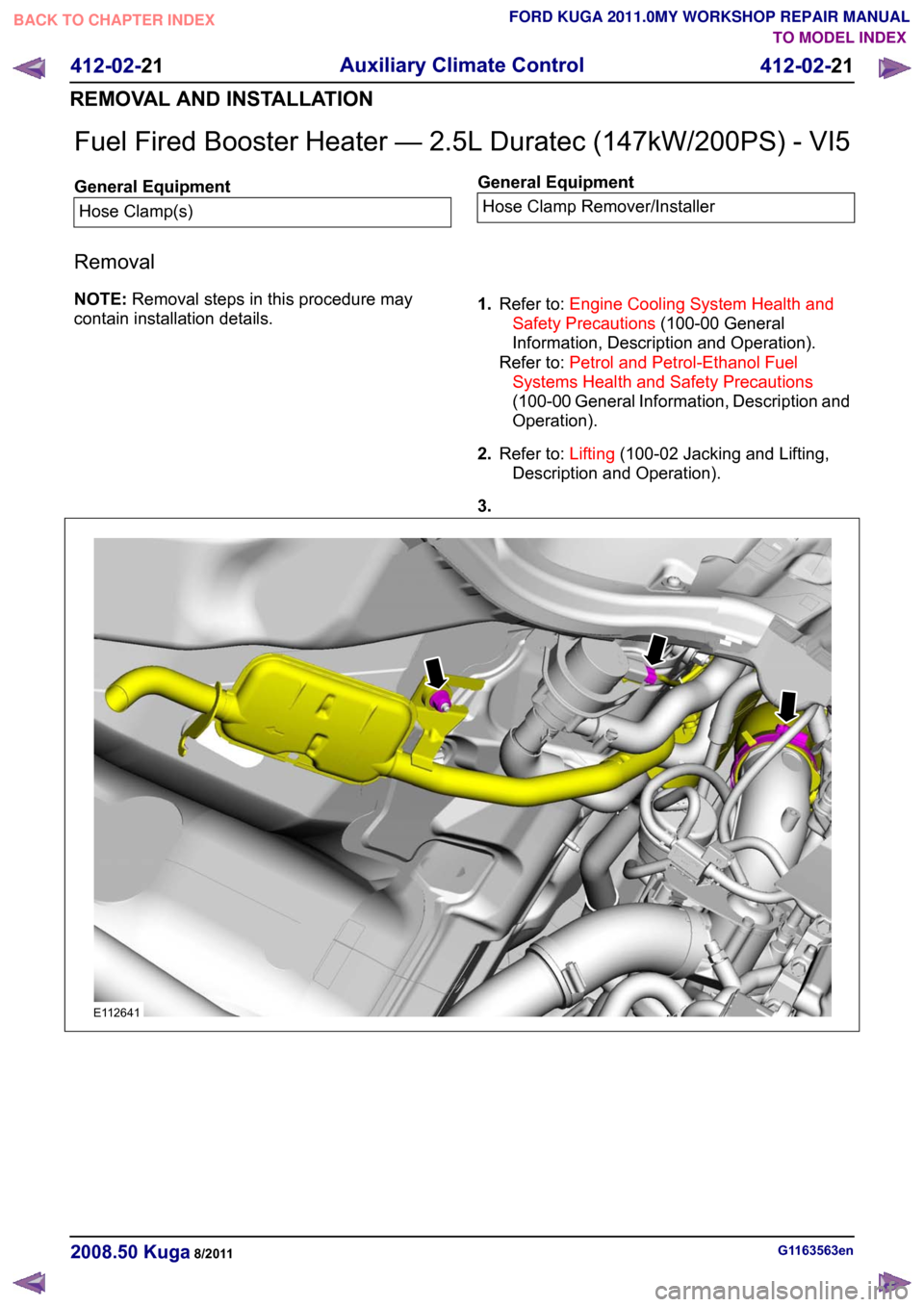
Fuel Fired Booster Heater — 2.5L Duratec (147kW/200PS) - VI5
General Equipment
Hose Clamp(s) General Equipment
Hose Clamp Remover/Installer
Removal
NOTE: Removal steps in this procedure may
contain installation details. 1.
Refer to: Engine Cooling System Health and
Safety Precautions (100-00 General
Information, Description and Operation).
Refer to: Petrol and Petrol-Ethanol Fuel
Systems Health and Safety Precautions
(100-00 General Information, Description and
Operation).
2. Refer to: Lifting(100-02 Jacking and Lifting,
Description and Operation).
3. G1163563en
2008.50 Kuga 8/2011 412-02-21
Auxiliary Climate Control
412-02-21
REMOVAL AND INSTALLATIONTO MODEL INDEX
BACK TO CHAPTER INDEX
FORD KUGA 2011.0MY WORKSHOP REPAIR MANUALE112641
Page 464 of 2057

Generic Electronic Module (GEM)
General Equipment
Ford Diagnostic Equipment
Removal
CAUTIONS: Modules must not be swapped between
vehicles.
Compare the number of relays and fuses
in the defective GEM and the new GEM.
Transfer from the defective GEM any relays
and fuses which are not in the new GEM.
In doing so, pay attention that fuses with
the correct Ampere rating are used, by
referring to the wiring diagrams.
When installing a new GEM on vehicles
with a diesel engine, make sure that a fuel
pump fuse (F111) with 5A is used.
When installing a new GEM on vehicles
with a petrol engine, make sure that a fuel
pump fuse (F111) with 15A is used.
NOTE: GEM is integrated into the central junction
box (CJB) and cannot be removed individually.
1. NOTE: This step is only necessary when
installing a new component.
Upload the GEM configuration information using
the Programmable Modules Installation Routine.
General Equipment: Ford Diagnostic Equipment
2. Refer to: Battery Disconnect and Connect
(414-01 Battery, Mounting and Cables,
General Procedures).
3. 4.
5.
Installation
1.
To install, reverse the removal procedure.
2. NOTE: This step is only necessary when
installing a new component.
Download the GEM configuration information
to the newly installed GEM using the
programmable modules installation routine.
3. NOTE: This step is only necessary when
installing a new component.
Program all keys using the Key Programming
Routine.
General Equipment: Ford Diagnostic Equipment G1065605en
2008.50 Kuga 8/2011 419-10-14
Multifunction Electronic Modules
419-10-14
REMOVAL AND INSTALLATIONTO MODEL INDEX
BACK TO CHAPTER INDEX
FORD KUGA 2011.0MY WORKSHOP REPAIR MANUALE51159 122E102019 E102020
Page 1319 of 2057
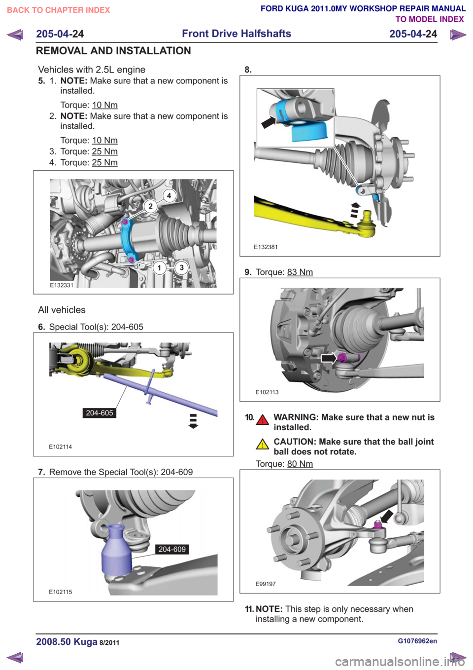
Vehicles with 2.5L engine
5. NOTE:Make sure that a new component is
installed.
Torque: 10
Nm
1.
2. NOTE: Make sure that a new component is
installed.
Torque: 10
Nm
3. Torque: 25Nm
4. Torque: 25Nm
2
4
13
2
4
13
E132331
All vehicles
6. Special Tool(s): 204-605
E102114
204-605
7.Remove the Special Tool(s): 204-609
E102115
204-609
8.
E132381
9.Torque: 83Nm
E102113
10. WARNING: Make sure that a new nut is
installed.
CAUTION: Make sure that the ball joint
ball does not rotate.
Torque: 80
Nm
E99197
11. NOTE: This step is only necessary when
installing a new component.
G1076962en2008.50 Kuga8/2011
205-04- 24
Front Drive Halfshafts
205-04- 24
REMOVAL AND INSTALLATION
TO MODEL INDEX
BACK TO CHAPTER INDEX
FORD KUGA 2011.0MY WORKSHOP REPAIR MANUAL
Page 1354 of 2057
4. Remove the vacuum hose from the brakebooster. Manifold vacuum should be available
at the brake booster end of the hose with the
engine at idle speed and the transaxle in the
NEUTRAL position. Make sure that all unused
vacuum outlets are correctly capped, hose
connectors are correctly secured and vacuum
hoses are in good condition. When it is
established that manifold vacuum is available
to the brake booster, connect the vacuum hose
to the brake booster and repeat Step 3. If no
downward movement of the brake pedal is felt,
install a new brake booster.
5. Operate the engine a minimum of 10 seconds at approximately 1200 rpm. Stop the engine and
let the vehicle stand for 10 minutes. Then, apply
the brake pedal with approximately 89 N (20 lb)
force. The pedal feel (brake application) should
be the same as that noted with the engine
operating. If the brake pedal feels hard (no
power assist), install a new vacuum check valve
and then repeat the test. If the brake pedal still
feels hard, install a new brake booster. If the
brake pedal movement feels spongy, bleed the
brake system. REFER to: (206-00 Brake System
- General Information)
Brake System Bleeding (General Procedures),
Brake System Pressure Bleeding (General
Procedures),
Component Bleeding (General Procedures).
Brake Master Cylinder
Usually, the first and strongest indicator of anything
wrong with the braking system is a feeling through
the brake pedal. In diagnosing the condition of the
brake master cylinder, check pedal feel as
evidence of a brake concern. Check for the red
brake warning indicator illumination and the fluid
level in the master cylinder reservoir.
Normal Conditions
The following conditions are considered normal
and are not indications that the brake master
cylinder is in need of service.
– Modern brake systems are not designed to
produce as hard a pedal effort as in the past.
Complaints of light pedal efforts should be compared to pedal efforts of another vehicle, of
the same model and year.
– During normal operation of the brake pedal, the fluid level in the reservoir will rise during brake
pedal application and fall during release. The
net fluid level (i.e., after brake pedal application
and release) will remain unchanged.
– A trace of brake fluid will exists on the brake booster shell below the master cylinder
mounting flange. This results from the normal
lubricating action of the master cylinder bore
end seal.
– The fluid level will fall with brake shoe and lining wear.
Abnormal Conditions
NOTE: Prior to performing any diagnosis, make
sure the brake system warning indicator is
functional.
Changes in brake pedal feel or travel are indicators
that something could be wrong with the braking
system. The diagnostic procedure and techniques
use brake pedal feel, warning indicator illumination
and low brake fluid level as indicators in diagnosing
braking system concerns. The following conditions
are considered abnormal and indicate that the
brake master cylinder is in need of service.
– The brake pedal goes down fast. This could be caused by an external or internal leak.
– The brake pedal eases down slowly. This could be caused by an external or internal leak.
– The brake pedal is low and or feels spongy. This condition may be caused by no fluid in the brake
master cylinder reservoir, reservoir cap vent
holes clogged or air in the hydraulic system.
– The brake pedal effort is excessive. This may be caused by a bind or obstruction in the pedal
or linkage, clogged fluid control valve or
insufficient booster vacuum.
– The rear brakes lock up during light pedal force. This may be caused by incorrect tire pressures,
grease or fluid on the brake shoes and linings,
damaged brake shoes and linings, incorrectly
adjusted parking brake, or damaged or
contaminated brake pressure control valves.
– The brake pedal effort is erratic. This condition could be caused by a brake booster malfunction,
extreme caliper piston knock back or incorrectly
installed brake shoes and linings.
– The red brake warning indicator is ON. This may be caused by low fluid level, ignition wire routing
G1058975en2008.50 Kuga8/2011
206-00- 18
Brake System - General Information
206-00- 18
DIAGNOSIS AND TESTING
TO MODEL INDEX
BACK TO CHAPTER INDEX
FORD KUGA 2011.0MY WORKSHOP REPAIR MANUAL
Page 1445 of 2057
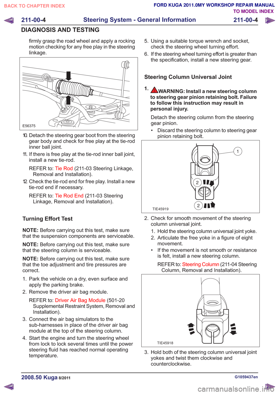
firmly grasp the road wheel and apply a rocking
motion checking for any free play in the steering
linkage.
E56375
10. Detach the steering gear boot from the steeringgear body and check for free play at the tie-rod
inner ball joint.
11. If there is free play at the tie-rod inner ball joint, install a new tie-rod.
REFER to: Tie Rod(211-03 Steering Linkage,
Removal and Installation).
12. Check the tie-rod end for free play. Install a new tie-rod end if necessary.
REFER to: Tie Rod End (211-03 Steering
Linkage, Removal and Installation).
Turning Effort Test
NOTE: Before carrying out this test, make sure
that the suspension components are serviceable.
NOTE: Before carrying out this test, make sure
that the steering column is serviceable.
NOTE: Before carrying out this test, make sure
that the toe adjustment and tire pressures are
correct.
1. Park the vehicle on a dry, even surface and apply the parking brake.
2. Remove the driver air bag module.
REFER to: Driver Air Bag Module (501-20
Supplemental Restraint System, Removal and
Installation).
3. Connect the air bag simulators to the sub-harnesses in place of the driver air bag
module at the top of the steering column.
4. Start the engine and turn the steering wheel from lock to lock several times until the power
steering fluid has reached normal operating
temperature. 5. Using a suitable torque wrench and socket,
check the steering wheel turning effort.
6. If the steering wheel turning effort is greater than the specification, install a new steering gear.
Steering Column Universal Joint
1.WARNING: Install a new steering column
to steering gear pinion retaining bolt. Failure
to follow this instruction may result in
personal injury.
Detach the steering column from the steering
gear pinion.• Discard the steering column to steering gear pinion retaining bolt.
TIE45919
1
2
2
2. Check for smooth movement of the steeringcolumn universal joint.
1. Hold the steering column universal joint yoke.
2. Articulate the free yoke in a figure of eight movement.
• If the movement is not smooth or resistance is felt, install a new steering column.
REFER to: Steering Column (211-04 Steering
Column, Removal and Installation).
TIE45918
3. Hold both of the steering column universal joint yokes and twist them clockwise and
counterclockwise.
G1059437en2008.50 Kuga8/2011
211-00- 4
Steering System - General Information
211-00- 4
DIAGNOSIS AND TESTING
TO MODEL INDEX
BACK TO CHAPTER INDEX
FORD KUGA 2011.0MY WORKSHOP REPAIR MANUAL
Page 1450 of 2057
Power Steering System Filling
Special Tool(s)211-189
Adapter, Power Steering
Bleeding
13016
416-D001
Hand Vacuum
Pump/Pressure Pump
23036A
Materials
Specification
Name
WSS-M2C204-A2 /
5U7J-M2C204-AA
Hydraulic Fluid DP-PS
1. Fill the power steering fluid reservoir to the MAX
mark.
Material: Hydraulic Fluid DP-PS
(WSS-M2C204-A2 / 5U7J-M2C204-AA)
hydraulic fluid
2. Raise the vehicle until the road wheels are clear
of the floor. Support the vehicle.
Refer to: Lifting(100-02 Jacking and Lifting,
Description and Operation).
3. Slowly turn the steering wheel from lock to lock
and add power steering fluid until the power
steering fluid in the power steering fluid reservoir
stops dropping.
4. Start the engine and slowly turn the steering
wheel from lock to lock and add power steering
fluid until the power steering fluid in the power
steering fluid reservoir stops dropping. 5.
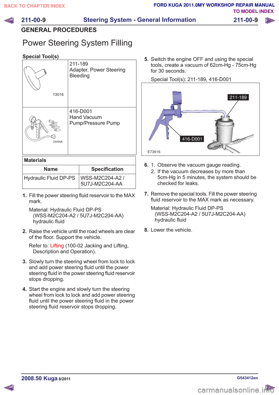
Switch the engine OFF and using the special
tools, create a vacuum of 62cm-Hg - 75cm-Hg
for 30 seconds.
Special Tool(s): 211-189, 416-D001
E73916
211-189
416-D001
6. Observe the vacuum gauge reading.
1.
2. If the vacuum decreases by more than
5cm-Hg in 5 minutes, the system should be
checked for leaks.
7. Remove the special tools. Fill the power steering
fluid reservoir to the MAX mark as necessary.
Material: Hydraulic Fluid DP-PS
(WSS-M2C204-A2 / 5U7J-M2C204-AA)
hydraulic fluid
8. Lower the vehicle.
G543412en2008.50 Kuga8/2011
211-00- 9
Steering System - General Information
211-00- 9
GENERAL PROCEDURES
TO MODEL INDEX
BACK TO CHAPTER INDEX
FORD KUGA 2011.0MY WORKSHOP REPAIR MANUAL