Page 3 of 655

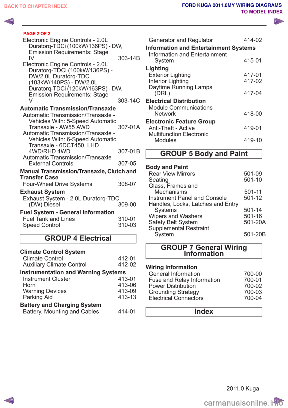
Electronic Engine Controls - 2.0LDuratorq-TDCi (100kW/136PS) - DW,
Emission Requirements: Stage
IV 303-14B
Electronic Engine Controls - 2.0L Duratorq-TDCi (100kW/136PS) -
DW/2.0L Duratorq-TDCi
(103kW/140PS) - DW/2.0L
Duratorq-TDCi (120kW/163PS) - DW,
Emission Requirements: Stage
V 303-14C
Automatic Transmission/Transaxle Automatic Transmission/Transaxle - Vehicles With: 5-Speed Automatic
Transaxle - AW55 AWD 307-01A
Automatic Transmission/Transaxle - Vehicles With: 6-Speed Automatic
Transaxle - 6DCT450, LHD
4WD/RHD 4WD 307-01B
Automatic Transmission/Transaxle External Controls 307-05
Manual Transmission/Transaxle, Clutch and
Transfer Case Four-Wheel Drive Systems 308-07
Exhaust System Exhaust System - 2.0L Duratorq-TDCi (DW) Diesel 309-00
Fuel System - General Information Fuel Tank and Lines 310-01
Speed Control 310-03
GROUP 4 Electrical
Climate Control System
Climate Control 412-01
Auxiliary Climate Control 412-02
Instrumentation and Warning Systems Instrument Cluster 413-01
Horn 413-06
Warning Devices 413-09
Parking Aid 413-13
Battery and Charging System Battery, Mounting and Cables 414-01 Generator and Regulator
414-02
Information and Entertainment Systems Information and Entertainment System 415-01
Lighting Exterior Lighting 417-01
Interior Lighting 417-02
Daytime Running Lamps (DRL) 417-04
Electrical Distribution Module Communications Network 418-00
Electronic Feature Group Anti-Theft - Active 419-01
Multifunction Electronic Modules 419-10
GROUP 5 Body and Paint
Body and Paint
Rear View Mirrors 501-09
Seating 501-10
Glass, Frames and Mechanisms 501-11
Instrument Panel and Console 501-12
Handles, Locks, Latches and Entry Systems 501-14
Wipers and Washers 501-16
Safety Belt System 501-20A
Supplemental Restraint System 501-20B
GROUP 7 General Wiring
Information
Wiring Information
General Information 700-00
Fuse and Relay Information 700-01
Power Distribution 700-02
Grounding Strategy 700-03
Electrical Connectors 700-04
Index
2011.0 Kuga
BACK TO CHAPTER INDEX
TO MODEL INDEXFORD KUGA 2011.0MY WIRING DIAGRAMS
PAGE 2 OF 2
Page 6 of 655

About This Manual
How to Use This Manual
This manual is structured into Systems, Groups
and Sections. A System covers a specific portion
of the vehicle. The manual is divided into six
Systems: General Information, Chassis,
Powertrain, Electrical, Body and Paint and General
Wiring Information. Each System contains a
number of Groups that contain a number ofSections relating to specific vehicle systems. Each
Section contains a wiring diagram containing all of
the information relating to the specific vehicle
system. Some Sections contain a number of wiring
diagrams that cover a number of different vehicle
variants. Connector location information and
connector face views are provided through links
within the wiring diagram for each vehicle system.
Example:
Chassis > Brake System > Anti-Lock
Control (System > Group > Section)
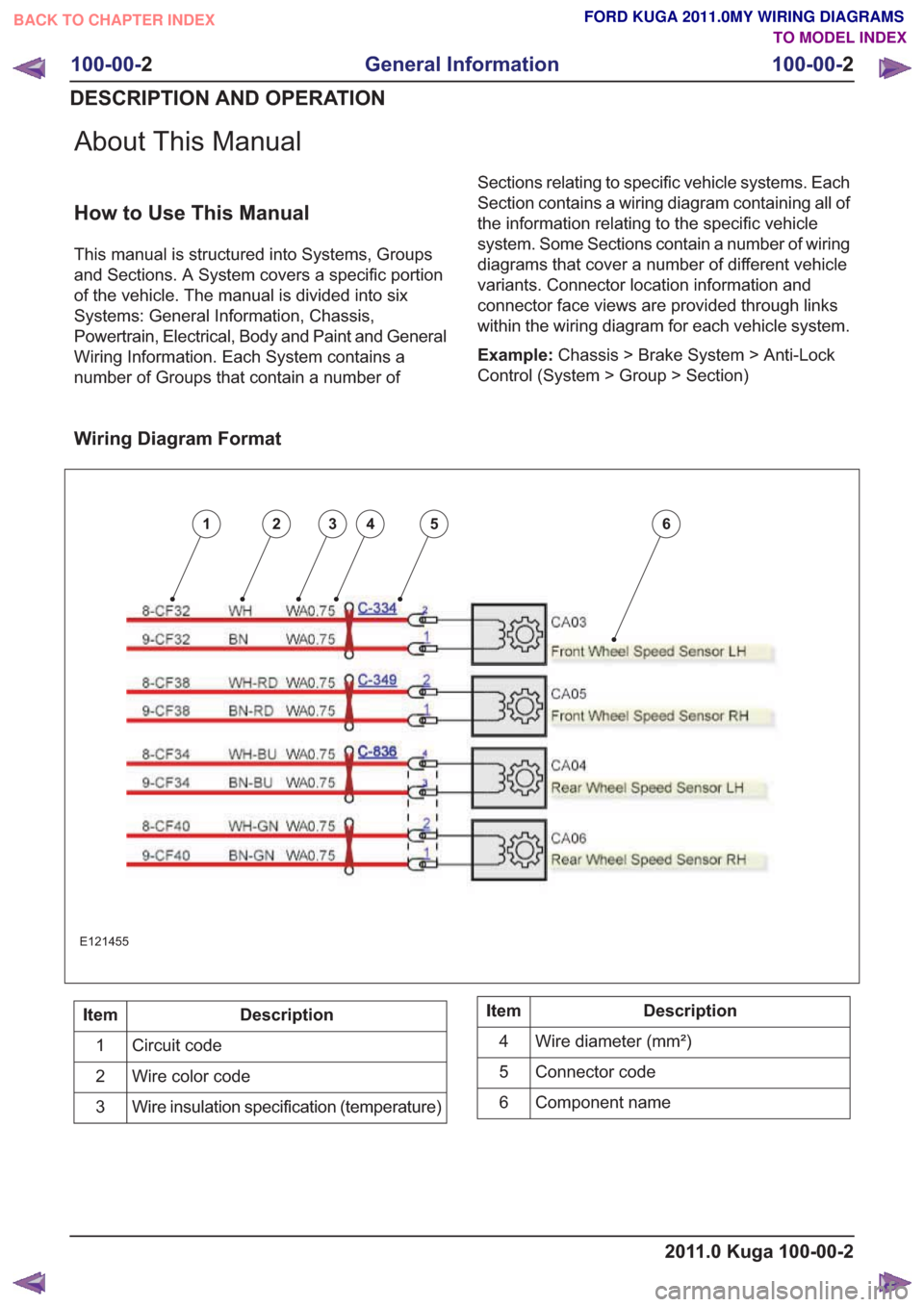
Wiring Diagram Format
123456
E121455
Description
Item
Circuit code
1
Wire color code
2
Wire insulation specification (temperature)
3Description
Item
Wire diameter (mm²)
4
Connector code
5
Component name
6
2011.0 Kuga 100-00-2
100-00- 2
General Information
100-00- 2
DESCRIPTION AND OPERATION
BACK TO CHAPTER INDEX TO MODEL INDEXFORD KUGA 2011.0MY WIRING DIAGRAMS
Page 7 of 655
Description
Position
Electrical potential
1
System
2
Sub-system
3
Function
4 and 5
Some circuit codes also have a suffix. Suffices are used when parts of a circuit are separated with a connector.
Position 1: Potential
Description
Code
GND (ground)
G
Standard voltage
S
Higher than standard voltage
H
Changing or switched
C
Variable signal
V
Lower than standard voltage
L
Return or reference
R
Drain wire
D
Any of the above with a temporary function
Z
Position 2: System
Description
Code
Power convenience
A
Circuit protection
B
Chassis
C
Electrical distribution
D
Diagnostic bus
E
Climate control
F
Information and entertainment
G
Heating
H
Supplemental restraints
J
Windshield wipers and washers
K
Lighting
L
2011.0 Kuga 100-00-3
100-00- 3
General Information
100-00- 3
DESCRIPTION AND OPERATION
Circuit Code
BACK TO CHAPTER INDEX TO MODEL INDEXFORD KUGA 2011.0MY WIRING DIAGRAMS
Page 9 of 655

Description
Sub-system Code
System Code
Diagnostic bus - audio communications protocol
A
E
Diagnostic bus - alternator
B
E
Diagnostic bus - CAN (controller area network)
C
E
Diagnostic bus - diagnostic connector link
D
E
Diagnostic bus - International Standards Organiza-
tion
E
E
Diagnostic bus - SCP (standard corporate protocol)
G
E
Climate control module
A
F
Climate control module
B
F
Auxiliary climate control
C
F
Instrument cluster, information and message
center, tachograph
A
G
Instrument cluster, information and message
center, tachograph
B
G
Instrument cluster, information and message
center, tachograph
C
G
Instrument cluster, information and message
center, tachograph
E
G
Instrument cluster
G
G
Instrument cluster, information and message
center, tachograph
H
G
Horn
J
G
Navigation
K
G
Anti-theft
L
G
Audible warnings and indicators
M
G
Parking aid
N
G
Vehicle emergency monitoring
P
G
Auxiliary climate control
A
H
Heated windshield, rear window, mirrors, washer
jets
B
H
Heated seats
C
H
RCM (restraints control module), air bag module,
side air curtain module
A
J
Windshield wipers and washers, rear window wiper
and washer, headlamp washers
A
K
Interior lamps, courtesy lamps
B
L
Interior lamps, courtesy lamps
C
L
2011.0 Kuga 100-00-5
100-00- 5
General Information
100-00- 5
DESCRIPTION AND OPERATION
BACK TO CHAPTER INDEX TO MODEL INDEXFORD KUGA 2011.0MY WIRING DIAGRAMS
Page 10 of 655
Description
Sub-system Code
System Code
Fog lamps
D
L
Headlamps
E
L
Exterior lighting
F
L
Turn signal and hazard lamps
G
L
Instrument cluster and panel illumination
H
L
Instrument panel illumination
K
L
Communication, cellular phone, voice control
C
M
Information and entertainment
D
M
Ambulance
A
N
Police
B
N
Ta x i
C
N
Trailer tow
D
N
Engine cooling
A
P
Speed control
G
P
Connectors
A
R
Destination notes
B
R
Powertrain controller, diode, driver, monitor, pump
D
R
PCM (powertrain control module)
E
R
Motors
G
R
Relays
H
R
Sensors
J
R
Solenoids
L
R
Splices or busbars
N
R
Switches
P
R
Engine ignition
R
R
Powertrain controller, diode, driver, monitor, pump
S
R
Transmission/transaxle, differential, axle
A
T
Automatic transmission
C
T
Transmission/transaxle, differential, axle
D
T
Temporary functions for any sub-system
L
X
2011.0 Kuga 100-00-6
100-00- 6
General Information
100-00- 6
DESCRIPTION AND OPERATION
BACK TO CHAPTER INDEX TO MODEL INDEXFORD KUGA 2011.0MY WIRING DIAGRAMS
Page 12 of 655
Symbols Glossary
E89368
1
2
3
4
5
6
7
8
9
10
Description
Item
In-line connector
1
Male connector
2
Female connector
3
Pins with special coating (e.g. gold)
4
Ground
5
Off-page reference (to)
6
Off-page reference (from)
7
Twisted pair
8
Screened cables
9
Part of a component
10
2011.0 Kuga 100-00-8
100-00- 8
General Information
100-00- 8
DESCRIPTION AND OPERATION
BACK TO CHAPTER INDEX TO MODEL INDEXFORD KUGA 2011.0MY WIRING DIAGRAMS
Page 14 of 655
SECTION 206-05 Parking Brake and Actuation
VEHICLE APPLICATION:2011.0 Kuga
PA G E
CONTENTS
ELECTRICAL CONNECTORS
206-05-2
Parking Brake Switch ........................................................................\
..................................
206-05-2
Parking Brake Switch ........................................................................\
..................................
206-05-1
Parking Brake and Actuation
206-05- 1
.
BACK TO CHAPTER INDEX TO MODEL INDEXFORD KUGA 2011.0MY WIRING DIAGRAMS
Page 16 of 655
SECTION 206-06 Hydraulic Brake Actuation
VEHICLE APPLICATION:2011.0 Kuga
PA G E
CONTENTS
ELECTRICAL CONNECTORS
206-06-2
Low Brake Fluid Warning Indicator Switch ........................................................................\
.
206-06-1
Hydraulic Brake Actuation
206-06- 1
.
BACK TO CHAPTER INDEX TO MODEL INDEXFORD KUGA 2011.0MY WIRING DIAGRAMS