2011 FORD F250 SUPER DUTY Fuse pa el passenger
[x] Cancel search: Fuse pa el passengerPage 179 of 449
WARNING: Never place your arm over the airbag module as a
deploying airbag can result in serious arm fractures or other
injuries.
To properly position yourself away from the airbag:
• Move your seat to the rear as far as you can while still reaching the
pedals comfortably.
• Recline the seat slightly one or two degrees from the upright position.
WARNING: Do not put anything on or over the airbag module.
Placing objects on or over the airbag inflation area may cause
those objects to be propelled by the airbag into your face and torso
causing serious injury.
WARNING: Do not attempt to service, repair, or modify the
airbag supplemental restraint systems or its fuses. Contact your
authorized dealer as soon as possible.
WARNING: The front passenger airbag is not designed to offer
protection to an occupant in the center front seating position.
WARNING: Modifying or adding equipment to the front end of
the vehicle (including frame, bumper, front end body structure
and tow hooks) may affect the performance of the airbag system,
increasing the risk of injury. Do not modify the front end of the
vehicle.
WARNING: Additional equipment such as snowplow equipment
may effect the performance of the airbag sensors increasing the
risk of injury. Please refer to the Body Builders Layout Book for
instructions about the appropriate installation of additional equipment.
Children and airbags
For additional important safety information, read all information on
safety restraints in this guide.
Children must always be properly restrained. Failure to follow these
instructions may increase the risk of injury in a collision. Seating and Safety Restraints
179
2011 F-250/350/450/550 (f23)
Owners Guide, 4th Printing
USA (fus)
Page 282 of 449
WARNING: Vehicles with a higher center of gravity such as
utility vehicles and trucks handle differently than vehicles with a
lower center of gravity. Utility vehicles and trucks are not designed for
cornering at speeds as high as passenger cars any more than low-slung
sports cars are designed to perform satisfactorily under off-road
conditions. Avoid sharp turns, excessive speed or abrupt maneuvers in
these vehicles. Failure to drive cautiously could result in an increased
risk of loss of vehicle control, vehicle rollover, personal injury and
death.
WARNING: Loaded vehicles, with a higher center of gravity,
may handle differently than unloaded vehicles. Do not overload
your vehicle and use extra precautions, such as driving at slower
speeds, avoiding abrupt steering changes and allowing for increased
stopping distance, when driving a heavily loaded vehicle. Over-loading
or loading the vehicle improperly can deteriorate handling capability
and contribute to loss of vehicle control and vehicle rollover.
BRAKE-SHIFT INTERLOCK
This vehicle is equipped with a brake-shift interlock feature that prevents
the gearshift lever from being moved from P (Park) when the ignition is
in the 3 (on) position and the brake pedal is not pressed.
If you cannot move the gearshift lever out of P (Park) with ignition in
the on position and the brake pedal pressed, it is possible that a fuse has
blown or the vehicle’s brake lamps are not operating properly. Refer to
Fuses and relays in the Roadside Emergencies chapter.
If the fuse is not blown and the brake lamps are working properly, the
following procedure will allow you to move the gearshift lever from P
(Park):
1. Apply the parking brake. Turn the ignition key to 1 (off), then remove
the key.
2. Move the steering column to the full down and full rearward position
(toward the driver’s seat).
3. Remove the gearshift lever boot.
4. Place fingers into hole where the gearshift lever boot was removed
from and pull top half of shroud up and forward to separate it from the
lower half of the shroud. There is a hinge at the forward edge of the top
shroud. Roll the top half of the shroud upward on the hinge point to
clear the hazard flasher button, then pull straight rearward toward the
driver’s seat to remove.Driving
282
2011 F-250/350/450/550 (f23)
Owners Guide, 4th Printing
USA (fus)
Page 312 of 449
Operating the vehicle with the snowplow attached
Do not use your vehicle for snow removal until it has been driven at
least 500 miles (800 km).
The attached snowplow blade restricts airflow to the radiator, and may
cause the engine to run at a higher temperature: Attention to engine
temperature is especially important when outside temperatures are
above freezing. Angle the blade to maximize airflow to the radiator and
monitor engine temperature to determine whether a left or right angle
provides the best performance.
Follow the severe duty schedule in your scheduled maintenance
information for engine oil and transmission fluid change intervals.
Snowplowing with your airbag-equipped vehicle
Your vehicle is equipped with a driver and passenger airbag
Supplemental Restraint System (SRS) The SRS is designed to activate in
certain frontal and offset frontal collisions when the vehicle sustains
sufficient longitudinal deceleration.
Careless or high speed driving while plowing snow which results in
sufficient vehicle decelerations can deploy the airbag. Such driving also
increases the risk of accidents.
WARNING: All occupants of the vehicle, including the driver,
should always properly wear their safety belts, even when an air
bag supplemental restraint system (SRS) is provided.
Never remove or defeat the “tripping mechanisms” designed into the
snow removal equipment by its manufacturer. Doing so may cause
damage to the vehicle and the snow removal equipment as well as
possible airbag deployment.
WARNING: Do not attempt to service, repair, or modify the air
bag supplemental restraint system (SRS) or its fuses. See your
Ford or Lincoln Mercury dealer.
WARNING: Additional equipment such as snowplow equipment
may effect the performance of the airbag sensors increasing the
risk of injury. Please refer to the Body Builders Layout Book for
instructions about the appropriate installation of additional equipment.Driving
312
2011 F-250/350/450/550 (f23)
Owners Guide, 4th Printing
USA (fus)
Page 317 of 449
Standard fuse amperage rating and color
COLOR
Fuse
rating Mini
fuses Standard
fuses Maxi
fuses Cartridge
maxi
fuses Fuse link
cartridge
2A Grey Grey — — —
3A Violet Violet — — —
4A Pink Pink — — —
5A Tan Tan — — —
7.5A Brown Brown — — —
10A Red Red — — —
15A Blue Blue — — —
20A Yellow Yellow Yellow Blue Blue
25A Natural Natural — Natural Natural
30A Green Green Green Pink Pink
40A — — Orange Green Green
50A — — Red Red Red
60A — — Blue Yellow Yellow
70A — — Tan — Brown
80A — — Natural Black Black
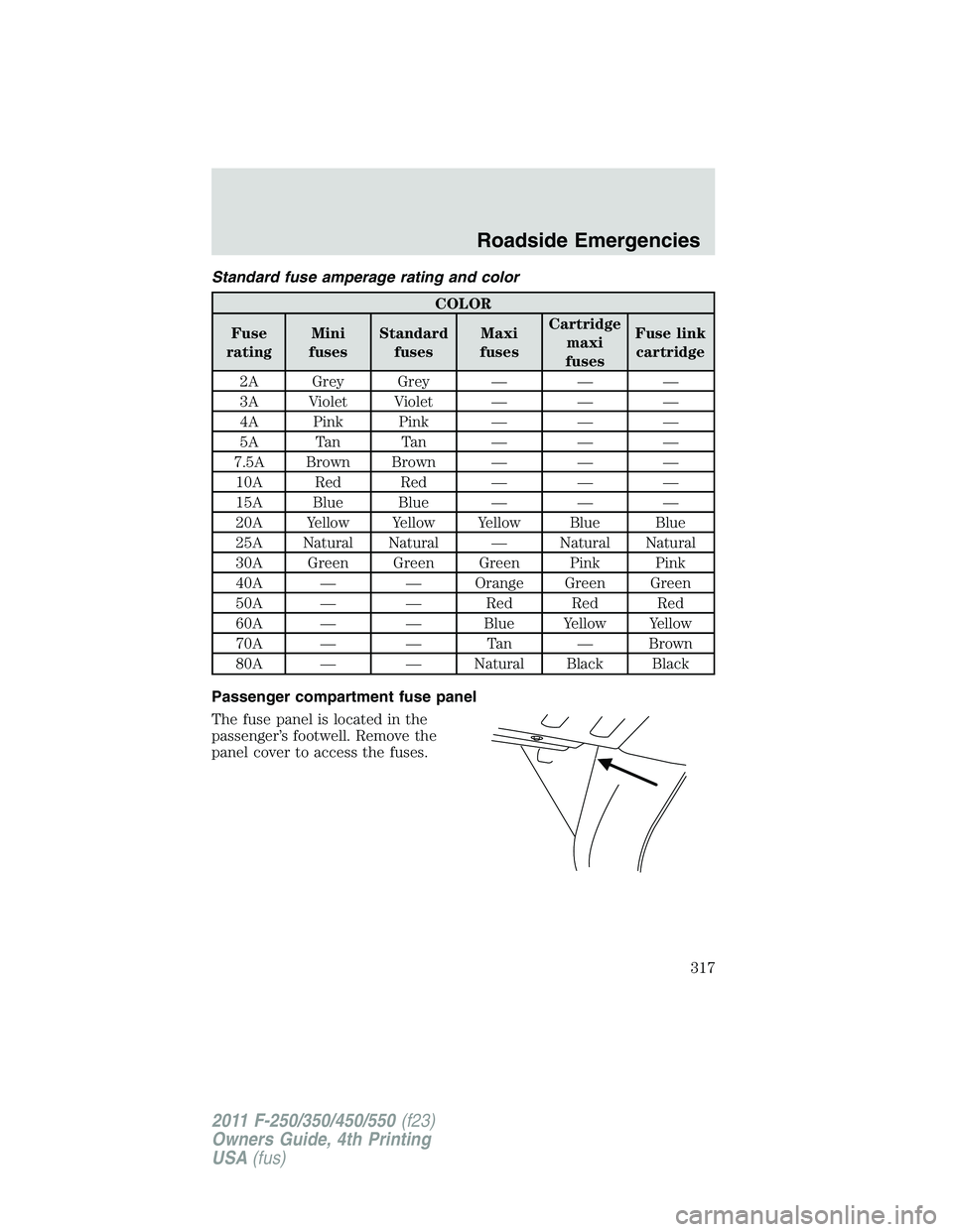
Passenger compartment fuse panel
The fuse panel is located in the
passenger’s footwell. Remove the
panel cover to access the fuses. Roadside Emergencies
317
2011 F-250/350/450/550 (f23)
Owners Guide, 4th Printing
USA (fus)
Page 318 of 449
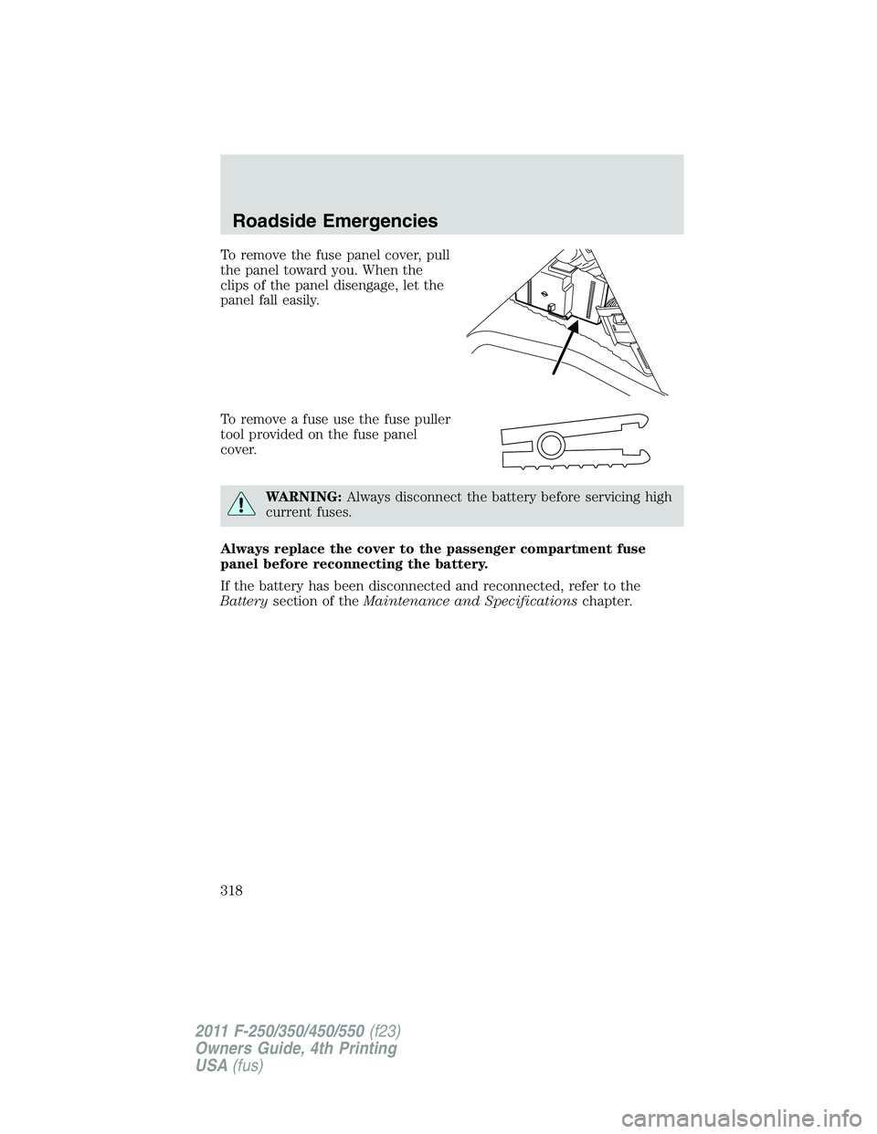
To remove the fuse panel cover, pull
the panel toward you. When the
clips of the panel disengage, let the
panel fall easily.
To remove a fuse use the fuse puller
tool provided on the fuse panel
cover.
WARNING: Always disconnect the battery before servicing high
current fuses.
Always replace the cover to the passenger compartment fuse
panel before reconnecting the battery.
If the battery has been disconnected and reconnected, refer to the
Battery section of the Maintenance and Specifications chapter.Roadside Emergencies
318
2011 F-250/350/450/550 (f23)
Owners Guide, 4th Printing
USA (fus)
Page 321 of 449
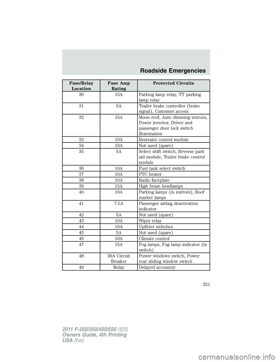
Fuse/Relay
Location Fuse Amp
Rating Protected Circuits
30 15A Parking lamp relay, TT parking
lamp relay
31 5A Trailer brake controller (brake
signal), Customer access
32 15A Moon roof, Auto dimming mirrors,
Power invertor, Driver and
passenger door lock switch
illumination
33 10A Restraint control module
34 10A Not used (spare)
35 5A Select shift switch, Reverse park
aid module, Trailer brake control
module
36 10A Fuel tank select switch
37 10A PTC heater
38 10A Radio faceplate
39 15A High beam headlamps
40 10A Parking lamps (in mirrors), Roof
marker lamps
41 7.5A Passenger airbag deactivation
indicator
42 5A Not used (spare)
43 10A Wiper relay
44 10A Upfitter switches
45 5A Not used (spare)
46 10A Climate control
47 15A Fog lamps, Fog lamp indicator (in
switch)
48 30A Circuit
Breaker Power windows switch, Power
rear sliding window switch
49 Relay Delayed accessory Roadside Emergencies
321
2011 F-250/350/450/550 (f23)
Owners Guide, 4th Printing
USA (fus)
Page 322 of 449
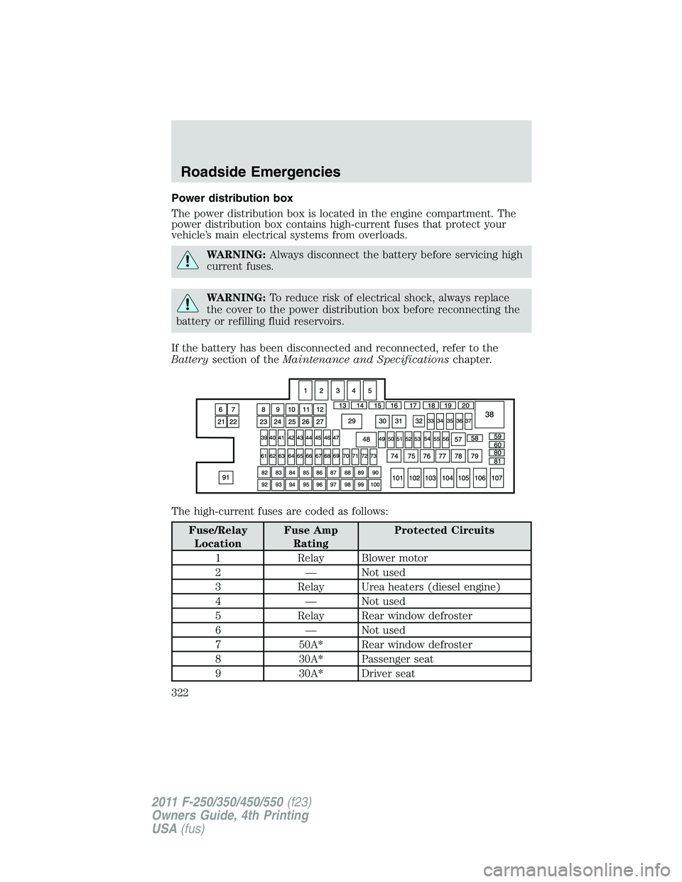
Power distribution box
The power distribution box is located in the engine compartment. The
power distribution box contains high-current fuses that protect your
vehicle’s main electrical systems from overloads.
WARNING: Always disconnect the battery before servicing high
current fuses.
WARNING: To reduce risk of electrical shock, always replace
the cover to the power distribution box before reconnecting the
battery or refilling fluid reservoirs.
If the battery has been disconnected and reconnected, refer to the
Battery section of the Maintenance and Specifications chapter.
The high-current fuses are coded as follows:
Fuse/Relay
Location Fuse Amp
Rating Protected Circuits
1 Relay Blower motor
2 — Not used
3 Relay Urea heaters (diesel engine)
4 — Not used
5 Relay Rear window defroster
6 — Not used
7 50A* Rear window defroster
8 30A* Passenger seat
9 30A* Driver seatRoadside Emergencies
322
2011 F-250/350/450/550 (f23)
Owners Guide, 4th Printing
USA (fus)
Page 324 of 449
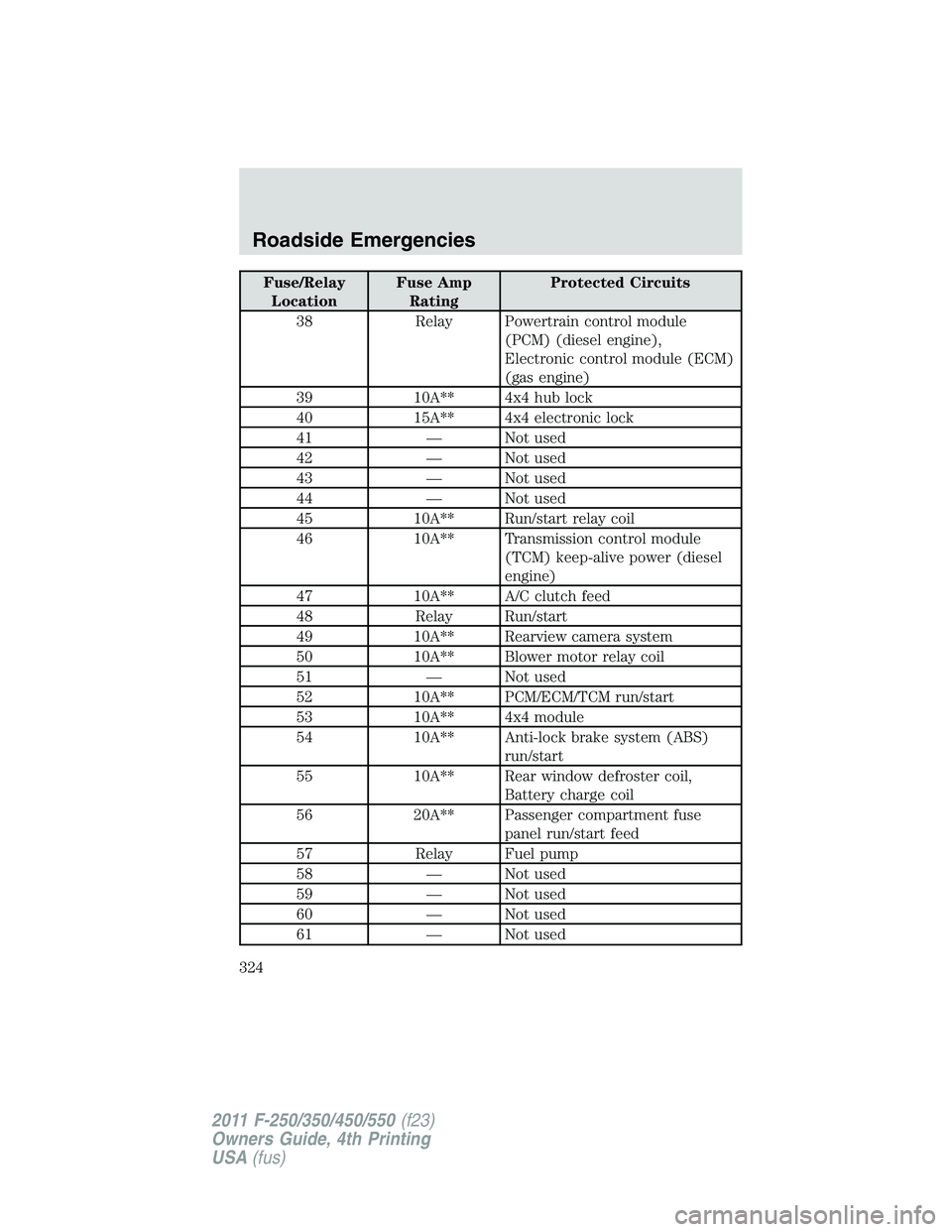
Fuse/Relay
Location Fuse Amp
Rating Protected Circuits
38 Relay Powertrain control module
(PCM) (diesel engine),
Electronic control module (ECM)
(gas engine)
39 10A** 4x4 hub lock
40 15A** 4x4 electronic lock
41 — Not used
42 — Not used
43 — Not used
44 — Not used
45 10A** Run/start relay coil
46 10A** Transmission control module
(TCM) keep-alive power (diesel
engine)
47 10A** A/C clutch feed
48 Relay Run/start
49 10A** Rearview camera system
50 10A** Blower motor relay coil
51 — Not used
52 10A** PCM/ECM/TCM run/start
53 10A** 4x4 module
54 10A** Anti-lock brake system (ABS)
run/start
55 10A** Rear window defroster coil,
Battery charge coil
56 20A** Passenger compartment fuse
panel run/start feed
57 Relay Fuel pump
58 — Not used
59 — Not used
60 — Not used
61 — Not usedRoadside Emergencies
324
2011 F-250/350/450/550 (f23)
Owners Guide, 4th Printing
USA (fus)