Page 328 of 461
If the battery has been disconnected and reconnected, refer to the
Batterysection of theMaintenance and Specificationschapter.
The high-current fuses are coded as follows:
Fuse/Relay
LocationFuse Amp
RatingProtected Circuits
1 — Powertrain control module (PCM)
relay (3.7L, 5.0L and 6.2L engines)
2 — Starter relay
3 — Blower motor relay
4 — Rear window defroster relay
5 — Electric fan relay (high speed)
6 — Trailer tow (TT) park lamp relay
7 — Run/start relay
8 — Fuel pump relay
9 — TT Battery charger relay
10 — PCM relay (3.5L engine)
11 30A** Power running board motors
1240A** Electric fan
50A** Electric fan (6.2L with max trailer
tow, SVT Raptor)
13 30A** Starter relay power
Roadside Emergencies
328
2011 F-150(f12)
Owners Guide, 1st Printing
USA(fus)
Page 329 of 461

Fuse/Relay
LocationFuse Amp
RatingProtected Circuits
14 30A** Passenger power seat
1540A** Electric fan
50A** Electric fan (6.2L with max trailer
tow, SVT Raptor)
16 — Not used
17 30A** Trailer brake control
18 30A** Upfitter 1 (SVT Raptor)
19 30A** Upfitter 2 (SVT Raptor)
20 20A** 4x4 module (electronic shift)
21 30A** TT battery charge relay power
22 20A** Cigar lighter
23 — A/C clutch relay
24 — Not used
25 — Vacuum pump relay (3.5L engine)
26 10A* PCM – keep alive power, PCM relay
coil, canister vent solenoid (3.7L,
5.0L and 6.2L engines)
27 20A* Fuel pump relay power
28 10A* Upfitter 4 (SVT Raptor)
29 10A* 4x4 IWE solenoid
30 10A* A/C clutch
31 15A* Run/start relay power
32 40A** Rear window defroster relay power
33 40A** 110V AC power point
34 40A** PCM relay power (3.7L, 5.0L and
6.2L engines)
50A** PCM relay power (3.5L engine)
35 — Not used
36 30A** Roll stability control (RSC)/Anti-lock
brake system (ABS)
37 — TT left stop/turn relay
38 — TT right stop/turn relay
Roadside Emergencies
329
2011 F-150(f12)
Owners Guide, 1st Printing
USA(fus)
Page 330 of 461
Fuse/Relay
LocationFuse Amp
RatingProtected Circuits
39 — TT back-up lamps relay
40 — Electric fan relay
41 — Not used
42 5A* Run/start coil
43 15A* TT back-up lamp relay power
44 15A* Upfitter 3 (SVT Raptor)
45 10A* Alternator sensor (non-6.2L engines)
46 10A* Brake on/off (BOO) switch
47 60A** RSC/ABS module
48 20A** Moon roof
49 30A** Wipers
50 — Not used
51 40A** Blower motor relay power
52 5A* Run/start – Electronic power assist
steering, Blower relay coil
53 5A* Run/start – PCM
54 5A* Run/start – 4x4 module, Back-up
lamps, RSC/ABS, TT battery charge
relay coil, Rear window defroster
relay coil
55 — Not used
56 15A* Heated mirrors
57 — Not used
58 — Not used
59 — Not used
60 — Not used
61 — Not used
62 — Wiper motor relay
63 25A** Electric fan
64 40A** Vacuum pump relay power (3.5L
engine)
Roadside Emergencies
330
2011 F-150(f12)
Owners Guide, 1st Printing
USA(fus)
Page 331 of 461

Fuse/Relay
LocationFuse Amp
RatingProtected Circuits
65 20A** Auxiliary power point (instrument
panel)
66 20A** Auxiliary power point (inside center
console)
67 20A** TT park lamps relay power
68 25A** 4x4 module
69 30A** Passenger heated/cooled seats
70 — Not used
71 20A** Heated rear seats
72 20A** Auxiliary power point (Rear)
73 20A** TT stop/turn lamps relay power
74 30A** Driver power seat/memory module
75 15A* PCM – voltage power 1 (3.7L, 5.0L,
6.2L engines PCM module)
25A* PCM – voltage power 1 (3.5L engine
PCM module)
76 20A* PCM – Voltage power 2 (General
powertrain components, Mass air
flow/Intake air temp sensor) (3.7L,
5.0L, 6.2L engines)
20A* PCM – Voltage power 2 (General
powertrain components, Canister
vent solenoid) (3.5L engine)
77 10A* PCM – Voltage power 3 (Emission
related powertrain components,
Electric fan relays coil)
78 15A* PCM – Voltage power4–Ignition
coils (3.5L, 3.7L, 5.0L engines)
20A* PCM – Voltage power4–Ignition
coils (6.2L engine)
79 5A* Rain sensor
80 — Not used
81 — Not used
Roadside Emergencies
331
2011 F-150(f12)
Owners Guide, 1st Printing
USA(fus)
Page 332 of 461
Fuse/Relay
LocationFuse Amp
RatingProtected Circuits
82 — Not used
83 — Not used
84 — Not used
85 — Electric fan relay (low speed)
*Mini fuse **Cartridge fuse
Auxiliary relay box (SVT Raptor only)
The relay box is located in the left rear corner of the engine
compartment.
Fuse/Relay
locationFuse amp
ratingDescription
1 — Upfitter 1 relay
2 — Upfitter 2 relay
3 — Upfitter 3 relay
4 — Upfitter 4 relay
5 — Not used
6 — Not used
CHANGING THE TIRES
If you get a flat tire while driving, do not apply the brake heavily.
Instead, gradually decrease your speed. Hold the steering wheel firmly
and slowly move to a safe place on the side of the road.
246
135
Roadside Emergencies
332
2011 F-150(f12)
Owners Guide, 1st Printing
USA(fus)
Page 335 of 461

•Load leveling adjustment (if applicable)
When driving with the full-size dissimilar spare tire/wheel additional
caution should be given to:
•Towing a trailer
•Driving vehicles equipped with a camper body
•Driving vehicles with a load on the cargo rack
Drive cautiously when using a full-size dissimilar spare tire/wheel and
seek service as soon as possible.
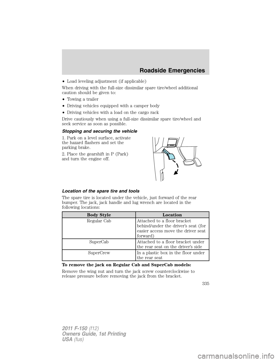
Stopping and securing the vehicle
1. Park on a level surface, activate
the hazard flashers and set the
parking brake.
2. Place the gearshift in P (Park)
and turn the engine off.
Location of the spare tire and tools
The spare tire is located under the vehicle, just forward of the rear
bumper. The jack, jack handle and lug wrench are located in the
following locations:
Body Style Location
Regular Cab Attached to a floor bracket
behind/under the driver’s seat (for
easier access move the driver seat
forward)
SuperCab Attached to a floor bracket under
the rear seat on the driver’s side
SuperCrew In a plastic box in the floor under
the rear seat
To remove the jack on Regular Cab and SuperCab models:
Remove the wing nut and turn the jack screw counterclockwise to
release pressure before removing the jack from the bracket.
Roadside Emergencies
335
2011 F-150(f12)
Owners Guide, 1st Printing
USA(fus)
Page 338 of 461
•Front
Note:Use the frame rail as the jacking location point, NOT the control
arm.
Note:For F-150 SVT Raptor, you must always use the jack saddle
extension.
•Rear
Note:Never use the front or rear
differential as a jacking point.
WARNING:To lessen the risk of personal injury, do not put any
part of your body under the vehicle while changing a tire. Do not
start the engine when your vehicle is on the jack. The jack is only
meant for changing the tire.
Roadside Emergencies
338
2011 F-150(f12)
Owners Guide, 1st Printing
USA(fus)
Page 342 of 461

Preparing your vehicle
When the battery is disconnected or a new battery is installed, the
automatic transmission must relearn its shift strategy. As a result, the
transmission may have firm and/or soft shifts. This operation is
considered normal and will not affect function or durability of the
transmission. Over time, the adaptive learning process will fully update
transmission operation.
1.Use only a 12–volt supply to start your vehicle.
2. Do not disconnect the battery of the disabled vehicle as this could
damage the vehicle’s electrical system.
3. Park the booster vehicle close to the hood of the disabled vehicle
making sure the two vehiclesdo nottouch. Set the parking brake on
both vehicles and stay clear of the engine cooling fan and other moving
parts.
4. Check all battery terminals and remove any excessive corrosion before
you attach the battery cables. Ensure that vent caps are tight and level.
5. Turn the heater fan on in both vehicles to protect from any electrical
surges. Turn all other accessories off.
Connecting the jumper cables
Note:In the illustration, the vehicle on the bottom is used to designate
the assisting (boosting) battery.
Roadside Emergencies
342
2011 F-150(f12)
Owners Guide, 1st Printing
USA(fus)