2011 DODGE JOURNEY lock
[x] Cancel search: lockPage 61 of 108

Uconnect Touch™ 8.4 Customer Programmable Features
• The Uconnect Touch™ 8.4 system allows you to access Customer Programmablefeature settings such as Display, Clock, Safety/Assistance, Lights, Doors & Locks,
Heated Seats, Engine Off Operation, Compass Settings, Audio, Phone/ Bluetooth
and SIRIUS Setup through soft-keys.
• Touch the More soft-key to on the bottom of the screen, then touch the Settings soft-key to access the Settings screen. When making a selection, scroll up or down
until the preferred setting is highlighted, then press and release the preferred
setting until a check-mark appears next to the setting, showing that setting has
been selected. The following feature settings are available:
• Display • Engine Off Options
• Clock • Compass Settings
• Safety / Assistance • Audio
• Lights • Phone / Bluetooth
• Doors & Locks • SIRIUS Setup
• Heated Seats
UNIVERSAL GARAGE DOOR OPENER
(HomeLink®)
Programming HomeLink®
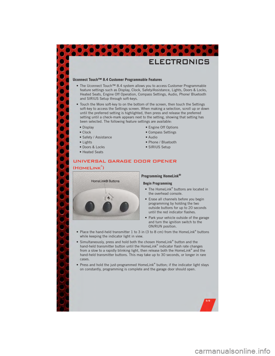
Begin Programming • The HomeLink®buttons are located in
the overhead console.
• Erase all channels before you begin programming by holding the two
outside buttons for up to 20 seconds
until the red indicator flashes.
• Park your vehicle outside of the garage and turn the ignition switch to the
ON/RUN position.
• Place the hand-held transmitter 1 to 3 in (3 to 8 cm) from the HomeLink
®buttons
while keeping the indicator light in view.
• Simultaneously, press and hold both the chosen HomeLink
®button and the
hand-held transmitter button until the HomeLink®indicator flash rate changes
from a slow to a rapidly blinking light, then release both the HomeLink®and the
hand-held transmitter buttons. This may take up to 30 seconds, or longer in rare
cases.
• Press and hold the just-programmed HomeLink
®button; if the indicator light stays
on constantly, programming is complete and the garage door should open.
ELECTRONICS
59
Page 63 of 108

POWER INVERTER
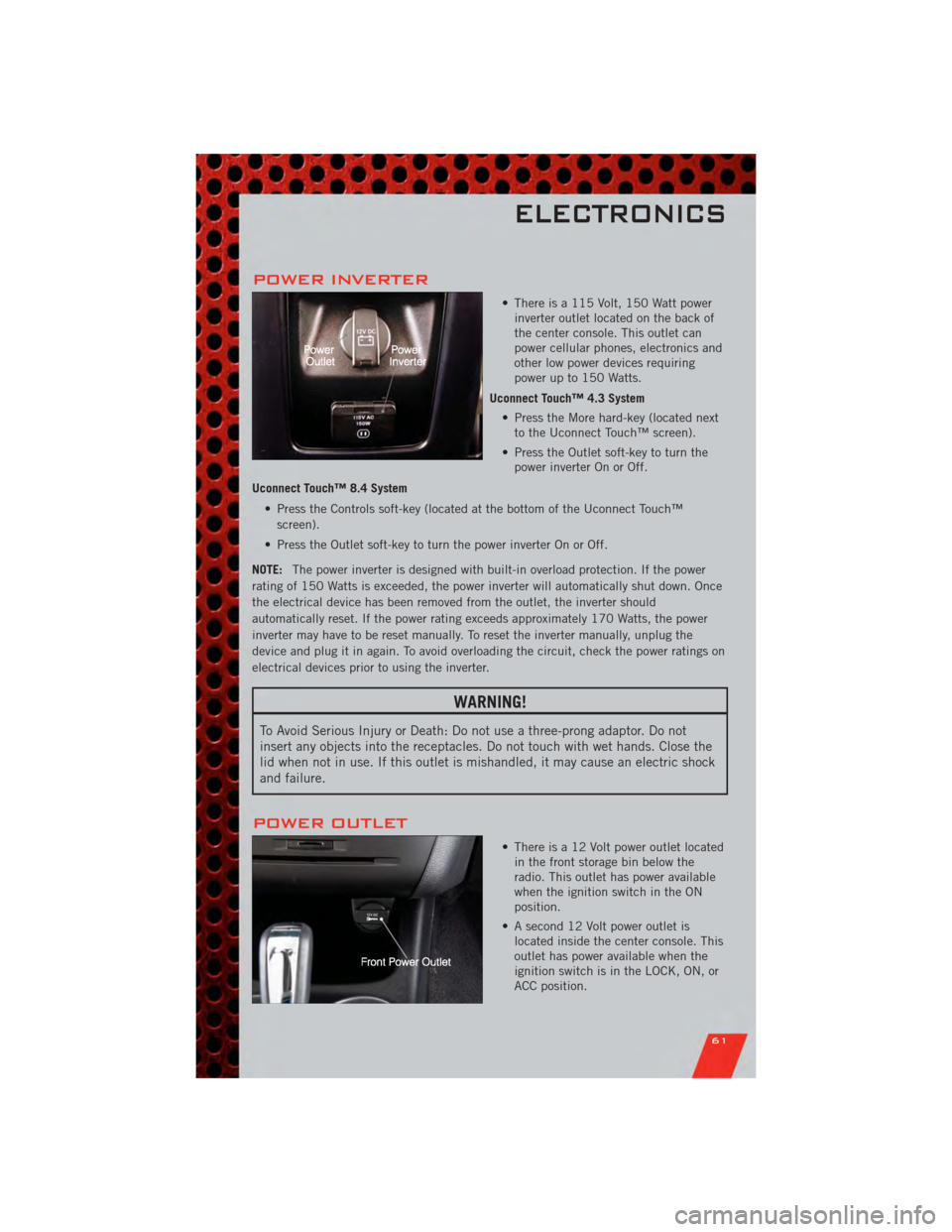
• There is a 115 Volt, 150 Watt powerinverter outlet located on the back of
the center console. This outlet can
power cellular phones, electronics and
other low power devices requiring
power up to 150 Watts.
Uconnect Touch™ 4.3 System • Press the More hard-key (located nextto the Uconnect Touch™ screen).
• Press the Outlet soft-key to turn the power inverter On or Off.
Uconnect Touch™ 8.4 System • Press the Controls soft-key (located at the bottom of the Uconnect Touch™screen).
• Press the Outlet soft-key to turn the power inverter On or Off.
NOTE: The power inverter is designed with built-in overload protection. If the power
rating of 150 Watts is exceeded, the power inverter will automatically shut down. Once
the electrical device has been removed from the outlet, the inverter should
automatically reset. If the power rating exceeds approximately 170 Watts, the power
inverter may have to be reset manually. To reset the inverter manually, unplug the
device and plug it in again. To avoid overloading the circuit, check the power ratings on
electrical devices prior to using the inverter.
WARNING!
To Avoid Serious Injury or Death: Do not use a three-prong adaptor. Do not
insert any objects into the receptacles. Do not touch with wet hands. Close the
lid when not in use. If this outlet is mishandled, it may cause an electric shock
and failure.
POWER OUTLET
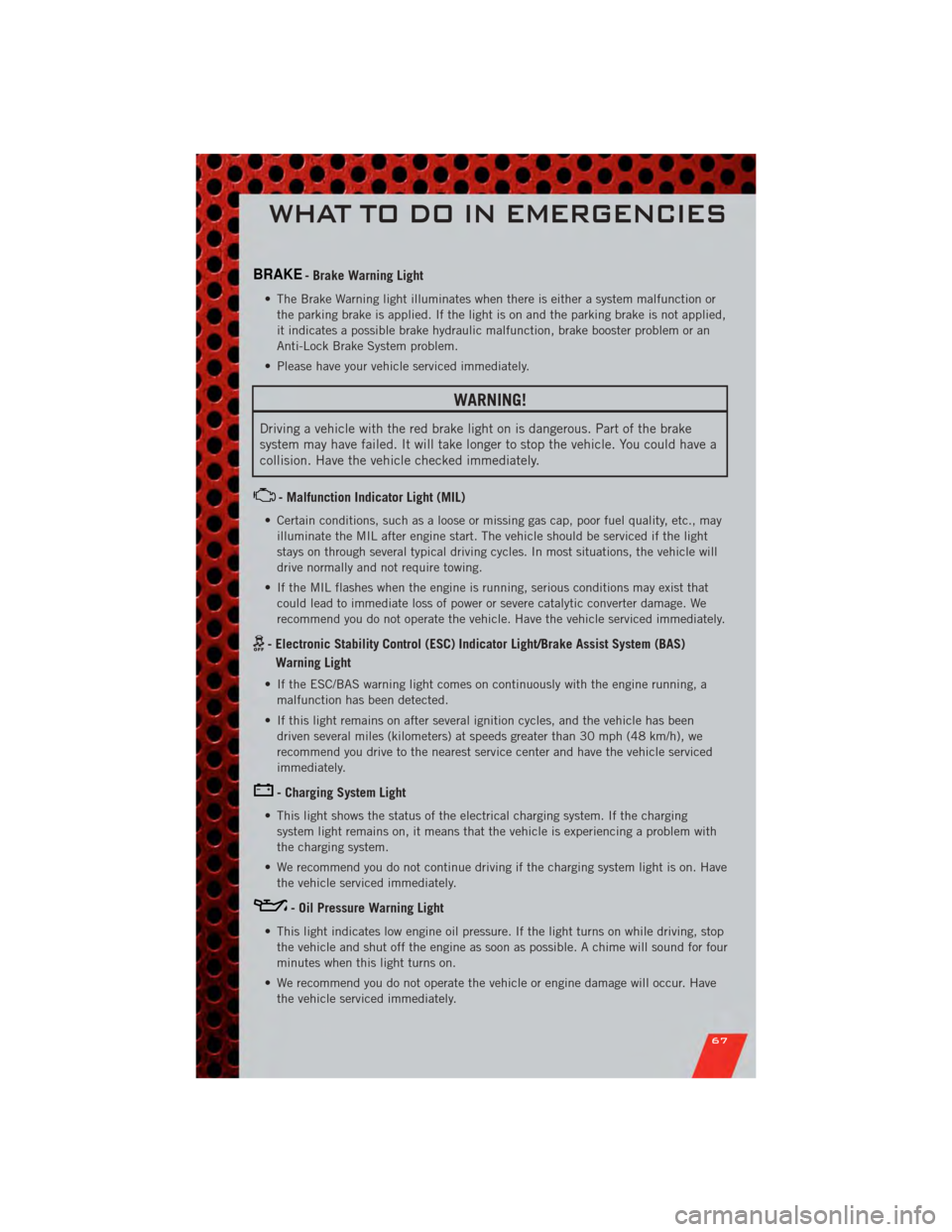
• There is a 12 Volt power outlet located in the front storage bin below the
radio. This outlet has power available
when the ignition switch in the ON
position.
• A second 12 Volt power outlet is located inside the center console. This
outlet has power available when the
ignition switch is in the LOCK, ON, or
ACC position.
ELECTRONICS
61
Page 64 of 108

• A third 12 Volt power outlet is located on the back of the center console. Thisoutlet has power available when the ignition switch is in the LOCK, ON or ACC
position.
• A fourth fused 12 Volt power outlet is located on the left quarter trim panel in the cargo area. This outlet has power available when the ignition switch is in the ON or
ACC position.
NOTE:
• Do not exceed the maximum power of 160 Watts (13 Amps) at 12 Volts. If the 160 Watt (13 Amp) power rating is exceeded, the fuse protecting the system will need to
be replaced.
• Power outlets are designed for accessory plugs only. Do not insert any other object in the power outlet as this will damage the outlet and blow the fuse. Improper use of
the power outlet can cause damage not covered by your new vehicle warranty.
ELECTRONICS
62
Page 69 of 108

BRAKE- Brake Warning Light
• The Brake Warning light illuminates when there is either a system malfunction orthe parking brake is applied. If the light is on and the parking brake is not applied,
it indicates a possible brake hydraulic malfunction, brake booster problem or an
Anti-Lock Brake System problem.
• Please have your vehicle serviced immediately.
WARNING!
Driving a vehicle with the red brake light on is dangerous. Part of the brake
system may have failed. It will take longer to stop the vehicle. You could have a
collision. Have the vehicle checked immediately.
- Malfunction Indicator Light (MIL)
• Certain conditions, such as a loose or missing gas cap, poor fuel quality, etc., may illuminate the MIL after engine start. The vehicle should be serviced if the light
stays on through several typical driving cycles. In most situations, the vehicle will
drive normally and not require towing.
• If the MIL flashes when the engine is running, serious conditions may exist that could lead to immediate loss of power or severe catalytic converter damage. We
recommend you do not operate the vehicle. Have the vehicle serviced immediately.
- Electronic Stability Control (ESC) Indicator Light/Brake Assist System (BAS)
Warning Light
• If the ESC/BAS warning light comes on continuously with the engine running, a malfunction has been detected.
• If this light remains on after several ignition cycles, and the vehicle has been driven several miles (kilometers) at speeds greater than 30 mph (48 km/h), we
recommend you drive to the nearest service center and have the vehicle serviced
immediately.
- Charging System Light
• This light shows the status of the electrical charging system. If the chargingsystem light remains on, it means that the vehicle is experiencing a problem with
the charging system.
• We recommend you do not continue driving if the charging system light is on. Have the vehicle serviced immediately.
- Oil Pressure Warning Light
• This light indicates low engine oil pressure. If the light turns on while driving, stopthe vehicle and shut off the engine as soon as possible. A chime will sound for four
minutes when this light turns on.
• We recommend you do not operate the vehicle or engine damage will occur. Have the vehicle serviced immediately.
WHAT TO DO IN EMERGENCIES
67
Page 70 of 108

- Anti-Lock Brake (ABS) Light
• This light monitors the Anti-Lock Brake System (ABS).
• If the light is not on during starting, stays on, or turns on while driving, werecommend you drive to the nearest service center and have the vehicle serviced
immediately.
- Electronic Throttle Control (ETC) Light
• This light informs you of a problem with the Electronic Throttle Control (ETC)system.
• If a problem is detected, the light will come on while the engine is running. Cycle the ignition when the vehicle has completely stopped and the shift lever is placed
in the PARK position; the light should turn off.
• If the light remains lit with the engine running, your vehicle will usually be drivable; however, see an authorized service center immediately. If the light is
flashing when the engine is running, immediate service is required and you may
experience reduced performance, an elevated/rough idle or engine stall and your
vehicle may require towing.
- Air Bag Warning Light
• If the light is not on during starting, stays on, or turns on while driving, have thevehicle serviced by an authorized service center immediately.
Fuel Cap/Loose Gas Cap Message
• If a “gas cap” message (shown as gASCAP) appears, tighten the gas cap until a“clicking” sound is heard.
• Press the odometer reset button to turn the message off.
• If the message continues to appear for more than three days after tightening the gas cap, see your authorized service center.
Oil Change Indicator
Message
• If an “oil change” message (shown as CHAngE OIL) appears and a single chime sounds, it is time for your next required oil change.
Resetting The Light After Servicing
• Turn the ignition switch to the ON/RUN position (do not start engine).
• Fully depress the accelerator pedal three times within 10 seconds.
• Turn the ignition switch to the OFF/LOCK position.
WHAT TO DO IN EMERGENCIES
68
Page 72 of 108

JACKING AND TIRE CHANGING
Jack Location
• The jack and jack-handle are stowed underneath a cover in the rear storage bin inthe cargo area.
• Remove the pouch containing the scissors jack, jack handle, and tools.
Spare Tire Stowage
NOTE: On Seven-Passenger Models, fold the third-row passenger seats flat. This will
provide more space when accessing the jacking tools and when operating the winch
mechanism.
• To remove the spare tire, remove the jack-handle components from the storage binin the cargo area and assemble them.
• Lower the spare tire by turning the spare tire drive nut, located in the jack storage area, counterclockwise with the jack-handle assembly until the spare tire is on the
ground with enough cable slack to allow you to pull the spare tire out from
underneath the vehicle.
• Raise the tire upright so the tire’s tread is on the ground and tilt the retainer at the end of the winch cable to remove it from the center of the wheel.
WHAT TO DO IN EMERGENCIES
70
Page 73 of 108

Preparations For Jacking
• Park on a firm, level surface. Avoid ice or slippery areas.
• Set the parking brake and place the shift lever into PARK.
• Turn the ignition to LOCK and turn on the Hazard Warning flasher.• Block both the front and rear of thewheel diagonally opposite of the
jacking position. For example, if
changing the right front tire, block the
left rear wheel.
NOTE: Passengers should not remain in the
vehicle when the vehicle is being jacked.
WHAT TO DO IN EMERGENCIES
71
Page 74 of 108

Jacking And Tire Changing Instructions
• Remove the spare tire, jack and tools from the stored location.
• Loosen (but do not remove) the wheel lug nuts by turning them counterclockwiseone turn while the wheel is still on the ground.
• Assemble the jack and jacking tools. Connect the jack handle driver to the extension, then to the lug wrench.
• Place the jack underneath the lift area that is closest to the flat tire. Turn the jack screw clockwise to firmly engage the jack saddle with the lift area of the sill flange.
• Raise the vehicle by turning the jackscrew clockwise. Raise the vehicle only
until the tire just clears the surface
and enough clearance is obtained to
install the spare tire.
• Remove the lug nuts, wheel cover (if equipped) and wheel.
• Position the spare wheel/tire on the vehicle and install the lug nuts with
the cone-shaped end toward the wheel.
Do NOT attempt to install a center cap
or wheel cover on the compact spare.
Lightly tighten the lug nuts clockwise.
To avoid the risk of forcing the vehicle
off the jack, do not tighten the nuts
fully until the vehicle has been
lowered.
• Lower the vehicle by turning the jack screw counterclockwise, and remove
the jack and wheel blocks.
• Finish tightening the lug nuts. Push down on the wrench while tightening
for increased leverage. Alternate nuts
until each one has been tightened
twice. The correct wheel nut tightness
is 95 ft lbs (130 N•m). If in doubt
about the correct tightness, have them
checked with a torque wrench by your
authorized dealer or at a service
station.
• Place the deflated (flat) tire and compact spare tire cover assembly in the rear cargo area. Do not stow the deflated tire in the spare tire location. Have the full-sized
tire repaired or replaced as soon as possible.
• To stow the winch cable and retainer, fit the assembled jack-handle over the winch drive nut. Rotate the jack-handle assembly clockwise until you hear the winch
mechanism click three times.
• Secure the jack and tools in their proper locations.
WHAT TO DO IN EMERGENCIES
72