Page 88 of 562

NOTE:If the speedometer, tachometer, or any engine
related gauges are not working, the Occupant Restraint
Controller (ORC) may also be disabled. The air bags may
not be ready to inflate for your protection. Promptly
check the fuse block for blown fuses. Refer to the label
located on the inside of the fuse block cover for the
proper air bag fuses. See your authorized dealer if the
fuse is good.
Event Data Recorder (EDR)
This vehicle is equipped with an event data recorder
(EDR). The main purpose of an EDR is to record, in
certain crash or near crash-like situations, such as an air
bag deployment or hitting a road obstacle, data that will
assist in understanding how a vehicle’s systems per-
formed. The EDR is designed to record data related to
vehicle dynamics and safety systems for a short period of
time, typically 30 seconds or less. The EDR in this vehicle
is designed to record such data as:
•How various systems in your vehicle were operating;
•Whether or not the driver and passenger safety belts
wer e buckled/fastened;
•How far (if at all) the driver was depressing the
accelerator and/or brake pedal; and,
•How fast the vehicle was traveling.
These data can help provide a better understanding of
the circumstances in which crashes and injuries occur.
NOTE: EDR data are recorded by your vehicle only if a
non-trivial crash situation occurs; no data are recorded by
the EDR under normal driving conditions and no per-
sonal data (e.g., name, gender, age, and crash location)
are recorded. However, other parties, such as law en-
forcement, could combine the EDR data with the type of
personally identifying data routinely acquired during a
crash investigation.
86 THINGS TO KNOW BEFORE STARTING YOUR VEHICLE
Page 212 of 562
The power outlets include tethered caps, labeled with a
key or battery symbol indicating the power source. The
power outlet, located on the lower instrument panel, is
powered directly from the battery. Items plugged into
this power outlet may discharge the battery and/or
prevent the engine from starting.
Power Outlet Fuses
1 — M7 Fuse 20 A Yellow Power Outlet Center Seat (Opt) or
with Console Rear
2 — M6 Fuse 20 A Yellow Cigar Lighter Instrument Panel or
with Console Front
3 — M36 Fuse 20 A Yellow Power Outlet Instrument Panel or
with Console Center
210 UNDERSTANDING THE FEATURES OF YOUR VEHICLE
Page 253 of 562

LoW tirE
When the appropriate condition exists, the odometer dis-
play will toggle between LoW and tirE for three cycles.
gASCAP
If the vehicle diagnostic system determines that the fuel
filler cap is loose, improperly installed, or damaged, a
“gASCAP” message will display in the odometer display
area. Tighten the fuel filler cap properly and press the
TRIP ODOMETER button to turn off the message. If the
problem continues, the message will appear the next time
the vehicle is started.
noFUSE
If the vehicle diagnostic system determines that the
Ignition Off Draw (IOD) fuse is improperly installed, or
damaged, a “noFUSE” message will display in the odom-
eter display area. For further information on fuses and
fuse locations refer to “Fuses” in “Maintaining Your
Vehicle”.CHAngE OIL
Your vehicle is equipped with an engine oil change
indicator system. The
CHAngE OILmessage will flash in
the instrument cluster odometer for approximately
12 seconds, after a single chime has sounded, to indicate
the next scheduled oil change interval. The engine oil
change indicator system is duty cycle-based, which
means the engine oil change interval may fluctuate
dependent upon your personal driving style.
Unless reset, this message will continue to display each
time you turn the ignition switch to the ON/RUN
position. To turn off the message temporarily, press and
release the Trip / Odometer Display reset button on the
instrument cluster. To reset the oil change indicator
system (after performing the scheduled maintenance),
perform the following steps.
1. Turn the ignition switch to the ON/RUN position (do
not start the engine).
4
UNDERSTANDING YOUR INSTRUMENT PANEL 251
Page 468 of 562
▫Automatic Transmission ............... 492
▫ Appearance Care And Protection From
Corrosion .......................... 494
▫ Cleaning The Instrument Panel Cupholders . . 499
� Fuses .............................. 499
▫ Totally Integrated Power Module ......... 499
� Vehicle Storage ....................... 506
� Replacement Bulbs .................... 507
� Bulb Replacement ..................... 507
▫ Headlamps ........................ 507
▫ Front Park/Turn Signal Lamps ........... 508▫
Fog Lamps ......................... 508
▫ Rear Tail, Stop, Turn Signal, Side Marker
And Backup Lamps ................... 509
▫ Center High-Mounted Stop Lamp
(CHMSL) .......................... 510
▫ License Lamp ....................... 510
� Fluid Capacities ...................... 511
� Fluids, Lubricants And Genuine Parts ....... 512
▫ Engine ............................ 512
▫ Chassis ........................... 513
466 MAINTAINING YOUR VEHICLE
Page 469 of 562
ENGINE COMPARTMENT — 3.6L
1 — Air Filter6 — Engine Coolant Reservoir
2 — Power Steering Fluid Reservoir 7 — Engine Oil Dipstick
3 — Brake Fluid Reservoir 8 — Engine Oil Fill
4 — Battery 9 — Coolant Pressure Cap
5 — Totally Integrated Power Module (Fuses) 10 — Washer Fluid Reservoir7
MAINTAINING YOUR VEHICLE 467
Page 501 of 562

Seat Belt Maintenance
Do not bleach, dye or clean the seat belts with chemical
solvents or abrasive cleaners. This will weaken the fabric.
Sun damage can also weaken the fabric.
If the seat belts need cleaning, use a mild soap solution or
lukewarm water. Do not remove the belts from the car to
wash them. Dry with a soft cloth.
Replace the seat belts if they appear frayed or worn, or if
the buckles do not work properly.
Cleaning The Instrument Panel Cupholders
Removal
Pull the flexible liner from the cupholder drawer starting
at one edge to ease removal.
Cleaning
The liner is top shelf dishwasher safe, or you may follow
the cleaning procedure below.Soak the liner in a mixture of medium hot tap water and
one teaspoon of mild liquid dish soap. Let soak for
approximately 30 minutes. After 30 minutes, pull the
liner from the water and dip it back into the water about
six times. This will loosen any remaining debris. Rinse
the liner thoroughly under warm running water. Shake
the excess water from the liner and dry the outer surfaces
with a clean soft cloth.
Installation
Place the liner into the cupholder drawer and press the
liner into place so that the retention tabs seat into the
corresponding openings in the drawer.
FUSES
Totally Integrated Power Module
The Totally Integrated Power Module is located in the
engine compartment near the battery. Refer to the appli-
cable “Engine Compartment” illustration in this section.
7
MAINTAINING YOUR VEHICLE 499
Page 502 of 562
This center contains cartridge fuses and mini-fuses. A
label that identifies each component may be printed or
embossed on the inside of the cover.CAUTION!
•When installing the Totally Integrated Power
Module cover, it is important to ensure the cover is
properly positioned and fully latched. Failure to
do so may allow water to get into the Integrated
Power Module, and possibly result in a electrical
system failure.
•When replacing a blown fuse, it is important to
use only a fuse having the correct amperage rating.
The use of a fuse with a rating other than indicated
may result in a dangerous electrical system over-
load. If a properly rated fuse continues to blow, it
indicates a problem in the circuit that must be
corrected.
Totally Integrated Power Module
500 MAINTAINING YOUR VEHICLE
Page 508 of 562

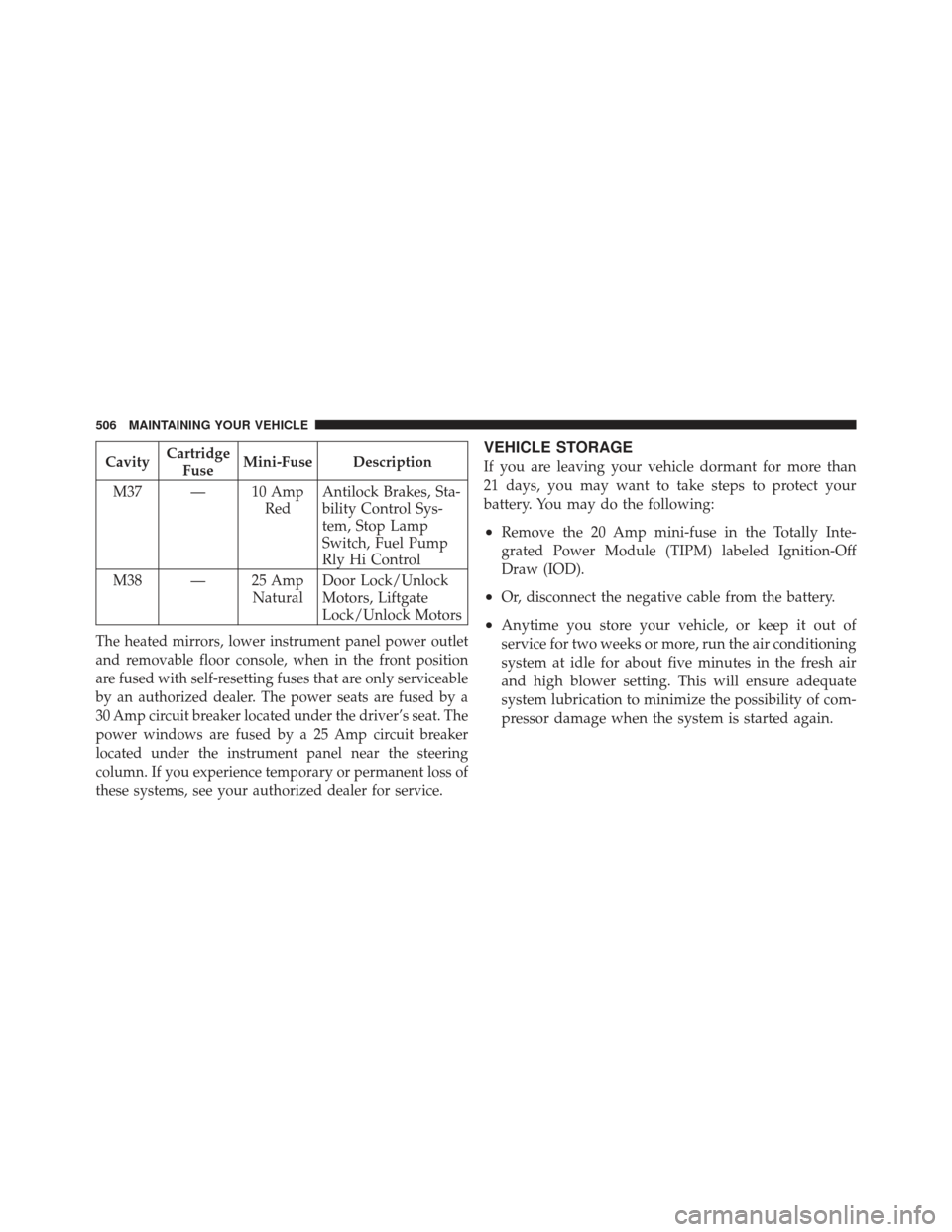
CavityCartridge
Fuse Mini-Fuse Description
M37 — 10 Amp RedAntilock Brakes, Sta-
bility Control Sys-
tem, Stop Lamp
Switch, Fuel Pump
Rly Hi Control
M38 — 25 Amp NaturalDoor Lock/Unlock
Motors, Liftgate
Lock/Unlock Motors
The heated mirrors, lower instrument panel power outlet
and removable floor console, when in the front position
are fused with self-resetting fuses that are only serviceable
by an authorized dealer. The power seats are fused by a
30 Amp circuit breaker located under the driver’s seat. The
power windows are fused by a 25 Amp circuit breaker
located under the instrument panel near the steering
column. If you experience temporary or permanent loss of
these systems, see your authorized dealer for service.
VEHICLE STORAGE
If you are leaving your vehicle dormant for more than
21 days, you may want to take steps to protect your
battery. You may do the following:
•Remove the 20 Amp mini-fuse in the Totally Inte-
grated Power Module (TIPM) labeled Ignition-Off
Draw (IOD).
•Or, disconnect the negative cable from the battery.
•Anytime you store your vehicle, or keep it out of
service for two weeks or more, run the air conditioning
system at idle for about five minutes in the fresh air
and high blower setting. This will ensure adequate
system lubrication to minimize the possibility of com-
pressor damage when the system is started again.
506 MAINTAINING YOUR VEHICLE