Page 178 of 562

wheel outward or push it inward as desired. To lock the
steering column in position, push the lever upward until
fully engaged.
WARNING!
Do not adjust the steering column while driving.
Adjusting the steering column while driving or driv-
ing with the steering column unlocked, could cause
the driver to lose control of the vehicle. Be sure the
steering column is locked before driving your ve-
hicle. Failure to follow this warning may result in
serious injury or death.
HEATED STEERING WHEEL — IF EQUIPPED
The steering wheel contains a heating element that helps
warm your hands in cold weather. The heated steering
wheel has only one temperature setting. Once the heated
steering wheel has been turned on it will operate for
approximately 58 to 70 minutes before automaticallyshutting off. The heated steering wheel can shut off early
or may not turn on when the steering wheel is already
warm.
The heated steering wheel switch is located on the switch
bank below the climate controls.
Press the switch to turn on the heated
steering wheel. The light on the switch
will illuminate to indicate the steering
wheel heater is on. Pressing the switch
a second time will turn off the heated
steering wheel and light indicator.
NOTE: The engine must be running for the heated
steering wheel to operate.
Vehicles Equipped With Remote Start
On models that are equipped with remote start, the
heated steering wheel can be programmed to come on
176 UNDERSTANDING THE FEATURES OF YOUR VEHICLE
Page 181 of 562

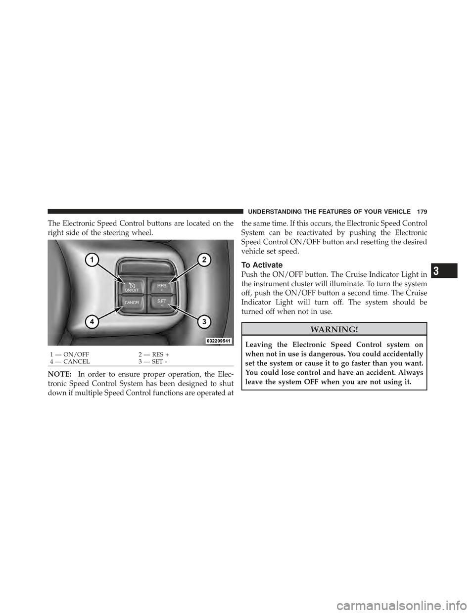
The Electronic Speed Control buttons are located on the
right side of the steering wheel.
NOTE:In order to ensure proper operation, the Elec-
tronic Speed Control System has been designed to shut
down if multiple Speed Control functions are operated at the same time. If this occurs, the Electronic Speed Control
System can be reactivated by pushing the Electronic
Speed Control ON/OFF button and resetting the desired
vehicle set speed.
To Activate
Push the ON/OFF button. The Cruise Indicator Light in
the instrument cluster will illuminate. To turn the system
off, push the ON/OFF button a second time. The Cruise
Indicator Light will turn off. The system should be
turned off when not in use.
WARNING!
Leaving the Electronic Speed Control system on
when not in use is dangerous. You could accidentally
set the system or cause it to go faster than you want.
You could lose control and have an accident. Always
leave the system OFF when you are not using it.
1 — ON/OFF
2 — RES +
4 — CANCEL 3 — SET -
3
UNDERSTANDING THE FEATURES OF YOUR VEHICLE 179
Page 183 of 562

To decrease speed while the Electronic Speed Control is
set, push the SET (-) button. If the button is continually
held in the SET (-) position, the set speed will continue to
decrease until the button is released. Release the button
when the desired speed is reached, and the new set speed
will be established.
Pressing the SET (-) button once will result ina1mph
(2 km/h) decrease in set speed. Each subsequent tap of
the button results in a decrease of 1 mph (2 km/h).
To Accelerate For Passing
Press the accelerator as you would normally. When the
pedal is released, the vehicle will return to the set speed.
Using Electronic Speed Control On Hills
The transmission may downshift on hills to maintain the
vehicle set speed.NOTE:
The Electronic Speed Control system maintains
speed up and down hills. A slight speed change on
moderate hills is normal.
On steep hills, a greater speed loss or gain may occur so
it may be preferable to drive without Electronic Speed
Control.
WARNING!
Electronic Speed Control can be dangerous where the
system cannot maintain a constant speed. Your ve-
hicle could go too fast for the conditions, and you
could lose control and have an accident. Do not use
Electronic Speed Control in heavy traffic or on roads
that are winding, icy, snow-covered or slippery.
3
UNDERSTANDING THE FEATURES OF YOUR VEHICLE 181
Page 213 of 562

WARNING!
To avoid serious injury or death:
•Only devices designed for use in this type of
outlet should be inserted into any 12 Volt outlet.
•Do not touch with wet hands.
•Close the lid when not in use and while driving
the vehicle.
•If this outlet is mishandled, it may cause an
electric shock and failure.
CAUTION!
•Many accessories that can be plugged in draw
power from the vehicle’s battery, even when not in
use (i.e., cellular phones, etc.). Eventually, if
plugged in long enough, the vehicle’s battery will
discharge sufficiently to degrade battery life
and/or prevent the engine from starting.
•Accessories that draw higher power (i.e., coolers,
vacuum cleaners, lights, etc.), will degrade the
battery even more quickly. Only use these inter-
mittently and with greater caution.
•After the use of high power draw accessories, or
long periods of the vehicle not being started (with
accessories still plugged in), the vehicle must be
driven a sufficient length of time to allow the
alternator to recharge the vehicle’s battery.(Continued)
3
UNDERSTANDING THE FEATURES OF YOUR VEHICLE 211
Page 226 of 562
Cargo Area Storage
The liftgate sill plate has a raised line with the statement
“Load To This Line”. This line indicates how far rearward
cargo can be placed without interfering with liftgate
closing.NOTE:
With all rear seats stowed or removed,4x8foot
sheets of building material will fit on the vehicle floor
with the liftgate closed. The front seats must be moved
slightly forward of the rearmost position.
CONSOLE FEATURES
There are three consoles available: Basic, Premium and
Super.
WARNING!
Do not operate this vehicle with a console compart-
ment lid in the open position. Cellular phones, music
players, and other handheld electronic devices
should be stowed while driving. Use of these devices
while driving can cause an accident due to distrac-
tion, resulting in death or injury.
Rear Cargo Area Loading Limit
224 UNDERSTANDING THE FEATURES OF YOUR VEHICLE
Page 231 of 562

To Remove The Premium Floor Console
1. Pull up on the bottom release handle in the front of the
console.
2. Lift the rear of the console up several inches/
centimeters.
3. Pull rearward to disengage from floor and remove
console.
To reinstall the console:
1. Position the console at a slight angle (rear slightly
higher than the front).
2. Slide the console forward into the floor bracket.
3. Rotate the rear of the console down until it is resting
on the floor bracket.4. Push down on the rear of the console until it is seated
in the rear floor bracket.
5. Pull up on the console to be sure it is firmly latched.
WARNING!
In an accident, serious injury could result if the
removable floor console is not properly installed.
Always be sure the removable floor console is fully
latched.
Super Console — If Equipped
The Super Console contains multiple storage areas, front
lower pass through, top forward bin, top rearward bin
and rear pull out drawer.
3
UNDERSTANDING THE FEATURES OF YOUR VEHICLE 229
Page 254 of 562

2. Fully depress the accelerator pedal, slowly, three times
within 10 seconds.
3. Turn the ignition switch to the OFF/LOCK position.
NOTE:If the indicator message illuminates when you
start the engine, the oil change indicator system did not
reset. If necessary, repeat these steps.
Compass Mini-Trip Computer (CMTC) Display — If
Equipped
On vehicles equipped with Compass Mini-Trip Com-
puter (CMTC), the display provides the outside tempera-
ture, one of eight compass headings to indicate the
direction the vehicle is facing, and the current radio
station. For further information, refer to “Compass Mini-
Trip Computer”. Electronic Vehicle Information Center (EVIC) Display
— If Equipped
The Electronic Vehicle Information Center (EVIC) fea-
tures a driver-interactive display that is located in the
instrument cluster. For further information, refer to
“Electronic Vehicle Information Center (EVIC)”.
7. Anti-Lock Brake (ABS) Light
This light monitors the Anti-Lock Brake System
(ABS). The light will turn on when the ignition
switch is turned to the ON/RUN position and
may stay on for as long as four seconds.
If the ABS light remains on or turns on while driving, it
indicates that the Anti-Lock portion of the brake system
is not functioning and that service is required. However,
the conventional brake system will continue to operate
normally if the BRAKE warning light is not on.
252 UNDERSTANDING YOUR INSTRUMENT PANEL
Page 256 of 562

Your vehicle has also been equipped with a TPMS
malfunction indicator to indicate when the system is not
operating properly. The TPMS malfunction indicator is
combined with the low tire pressure telltale. When the
system detects a malfunction, the telltale will flash for
approximately one minute and then remain continuously
illuminated. This sequence will continue upon subse-
quent vehicle start-ups as long as the malfunction exists.
When the malfunction indicator is illuminated, the sys-
tem may not be able to detect or signal low tire pressure
as intended. TPMS malfunctions may occur for a variety
of reasons, including the installation of replacement or
alternate tires or wheels on the vehicle that prevent the
TPMS from functioning properly. Always check the
TPMS malfunction telltale after replacing one or more
tires or wheels on your vehicle, to ensure that the
replacement or alternate tires and wheels allow the TPMS
to continue to function properly.CAUTION!
The TPMS has been optimized for the original
equipment tires and wheels. TPMS pressures and
warning have been established for the tire size
equipped on your vehicle. Undesirable system opera-
tion or sensor damage may result when using re-
placement equipment that is not of the same size,
type, and/or style. Aftermarket wheels can cause
sensor damage. Do not use tire sealant from a can or
balance beads if your vehicle is equipped with a
TPMS, as damage to the sensors may result.
9. Malfunction Indicator Light (MIL) The Malfunction Indicator Light (MIL) is part of
an onboard diagnostic system, called OBD, that
monitors engine and automatic transmission con-
trol systems. The light will illuminate when the key is in
the ON/RUN position, before engine start. If the bulb
254 UNDERSTANDING YOUR INSTRUMENT PANEL