Page 164 of 562

3. Press and release the memory SET (S) button located
on the driver’s door. A chime will sound signaling that
you are in the memory set mode.
4. Within five seconds, press and release MEMORY
button 1 on the driver’s door. A chime will sound
signaling to you that the driver memory has been set.
5. Within five seconds, press and release the UNLOCK
button on the RKE transmitter. A chime will sound
signaling to you that the RKE transmitter link has been
successfully disabled.
To disable another RKE transmitter linked to either
Memory Position, repeat Steps 1 to 5 for each RKE
transmitter.
NOTE:Once programmed, all RKE transmitters linked
to memory can be easily enabled or disabled at one time.
Refer to “Electronic Vehicle Information Center (EVIC)/
Customer-Programmable Features� in “Understanding
Your Instrument Panel” for further information.Easy Entry/Exit Seat (Available With Memory Seat
ONLY)
This feature provides automatic driver seat positioning to
enhance driver mobility when entering and exiting the
vehicle.
The distance the driver seat moves depends on where
you have the driver seat positioned when you remove the
key from the ignition switch.
•When you remove the key from the ignition switch, the
driver seat will move about 2.4 in (60 mm) rearward if
the driver seat position is greater than or equal to 2.7 in
(67.7 mm) forward of the rear stop. The seat will return
to its previously set position when you insert the key into
the ignition switch and turn it out of the LOCK position.
•When you remove the key from the ignition switch the
driver seat will move to a position 0.3 in (7.7 mm)
forward of the rear stop if the driver seat position is
between 0.9 – 2.7 in (22.7 – 67.7 mm) forward of the
162 UNDERSTANDING THE FEATURES OF YOUR VEHICLE
Page 169 of 562

Daytime Running Lights — If Equipped
The headlights on your vehicle will illuminate when the
engine is started and the transmission is in any gear
except PARK. This provides a constant lights on condi-
tion until the ignition is turned OFF. The lights illuminate
at less than 50% of normal intensity. If the parking brake
is applied, the Daytime Running Lights (DRL) will turn
off. Also, if a turn signal is activated, the DRL lamp on the
same side of the vehicle will turn off for the duration of
the turn signal activation. Once the turn signal is no
longer active, the DRL lamp will illuminate.
Front Fog Lights — If Equipped
To activate the front fog lights, turn on the parking
lights or the low beam headlights and push in the
headlight switch control knob. Pressing the head-
light switch control knob in a second time will turn the
front fog lights off.
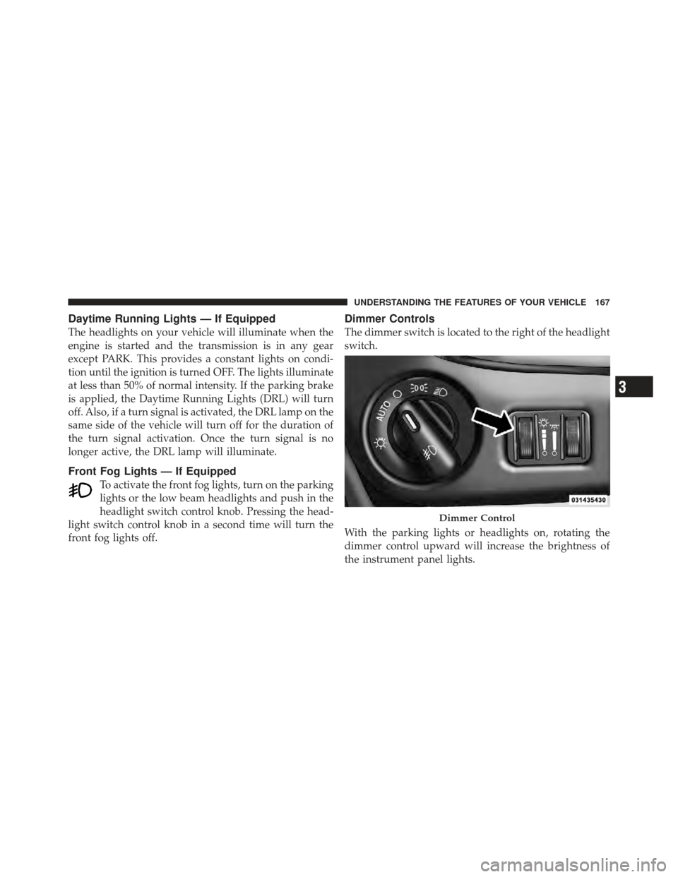
Dimmer Controls
The dimmer switch is located to the right of the headlight
switch.
With the parking lights or headlights on, rotating the
dimmer control upward will increase the brightness of
the instrument panel lights.
Dimmer Control
3
UNDERSTANDING THE FEATURES OF YOUR VEHICLE 167
Page 171 of 562
To activate the Halo lights, rotate the Halo
switch control upward or downward to in-
crease or decrease the lighting.
Multifunction Lever
The multifunction lever is located on the left side of the
steering column.
The multifunction lever controls the:
•Turn Signals
Halo Control
Multifunction Lever
3
UNDERSTANDING THE FEATURES OF YOUR VEHICLE 169
Page 172 of 562

•Headlight Beams Low/High
•Flash-To-Pass (Optical Horn)
•Front and Rear Wipers — Washer Functions
Turn Signals
Move the multifunction lever up or down and the arrows
on each side of the instrument cluster flash to show
proper operation of the front and rear turn signal lights.
NOTE:If either light remains on and does not flash, or
there is a very fast flash rate, check for a defective outside
light bulb. If an indicator fails to light when the lever is
moved, it would suggest that the indicator bulb is
defective.
Turn Signal Warning
If the vehicle electronics sense that the vehicle has
traveled at over 18 mph (29 km/h) for about 1 mile
(1.6 km) with the turn signals on, a chime will sound to
alert the driver.
Lane Change Assist
Tap the lever up or down once, without moving beyond
the detent, and the turn signal (right or left) will flash
three times then automatically turn off.
High/Low Beam Switch
When the headlights are turned on, pushing the multi-
function lever toward the instrument panel will switch
from low beams to high beams. Pulling back to the
neutral position returns the headlights to the low beam
operation.
Flash-To-Pass
You can signal another vehicle with your headlights by
lightly pulling the multifunction lever toward you. This
will cause the headlights to turn on at high beam and
remain on until the lever is released.
170 UNDERSTANDING THE FEATURES OF YOUR VEHICLE
Page 201 of 562

Programming HomeLink�
Before You Begin
If you have not trained any of the HomeLink� buttons,
erase all channels before you begin training.
To do this, press and hold the two outside buttons for up
to 20 seconds until the red indicator flashes.
It is recommended that a new battery be placed in the
handheld transmitter of the device that is being copied to
HomeLink� for more efficient training and accurate
transmission of the radio-frequency signal.
Your vehicle should be parked outside of the garage
when programming.
1. Turn the ignition switch to the ON/RUN position.
2. Hold the battery side of the handheld transmitter
away from the HomeLink� button you wish to program. Place the handheld transmitter 1 to 3 in (3 to 8 cm) away
from the HomeLink�
button you wish to program while
keeping the indicator light in view.
3. Simultaneously press and hold both the chosen
HomeLink� button and the handheld transmitter button
until the HomeLink� indicator changes from a slow to a
rapidly blinking light, then release both the HomeLink�
and handheld transmitter buttons.
Watch for the HomeLink� indicator to change flash rates.
When it changes, it is programmed. It may take up to
30 seconds or longer in rare cases. The garage door may
open and close while you train.
NOTE:
•Some gate operators and garage door openers may
require you to replace Step 3 with procedures noted in
the “Gate Operator/Canadian Programming” section.
3
UNDERSTANDING THE FEATURES OF YOUR VEHICLE 199
Page 203 of 562

6. Firmly press and release the LEARN or TRAINING
button. The name and color of the button may vary by
manufacturer.
NOTE:You have 30 seconds in which to initiate the next
step after the LEARN button has been pressed.
7. Return to the vehicle and press the programmed
HomeLink� button twice (holding the button for two
seconds each time). If the device is plugged in and
activates, programming is complete.
If the device does not activate, press the button a third
time (for two seconds) to complete the training.
If you have any problems, or require assistance, please
call toll-free 1–800–355–3515 or, on the Internet at
www.HomeLink.com for information or assistance.
To program the remaining two HomeLink� buttons,
repeat each step for each remaining button. DO NOT
erase the channels.Gate Operator/Canadian Programming
Canadian radio frequency laws require transmitter sig-
nals to time-out (or quit) after several seconds of trans-
mission – which may not be long enough for HomeLink �
to pick up the signal during programming. Similar to this
Canadian law, some U.S. gate operators are designed to
time-out in the same manner.
It may be helpful to unplug the device during the cycling
process to prevent possible overheating of the garage
door or gate motor.
If you are having difficulties programming a garage door
opener or a gate operator, replace “Programming
HomeLink�” Step 3, with the following:
3. Continue to press and hold the HomeLink �button,
while you press and release (“cycle”), your handheld trans-
mitter every two seconds until HomeLink �has success-
fully accepted the frequency signal. The indicator light will
flash slowly and then rapidly when fully trained.
3
UNDERSTANDING THE FEATURES OF YOUR VEHICLE 201
Page 251 of 562

INSTRUMENT CLUSTER DESCRIPTIONS
1. Tachometer
The red segments indicate the maximum permissible
engine revolutions per minute (RPM x 1000) for each gear
range. Before reaching the red area, ease up on the
accelerator.
2. Front Fog Light Indicator — If EquippedThis indicator will illuminate when the front fog
lights are on.
3. Park/Headlight ON Indicator — If Equipped This indicator will illuminate when the park
lights or headlights are turned on.
4. Turn Signal Indicators The arrow will flash with the exterior turn signal
when the turn signal lever is operated. If the vehicle is driven 1 mile (1.6 km) with either turn
signal on, a continuous chime will sound to alert you to
turn the signal off. If either indicator flashes at a rapid
rate, check for a defective outside light bulb.
5. High Beam Indicator
This indicator shows that the high beam head-
lights are on. Push the multifunction lever forward
to switch the headlights to high beam, and pull toward
yourself (normal position) to return to low beam.
6. Compass Mini-Trip Computer (CMTC) or Electronic
Vehicle Information Center (EVIC) Display — If
Equipped
Odometer
The odometer display shows the total distance the ve-
hicle has been driven.
4
UNDERSTANDING YOUR INSTRUMENT PANEL 249
Page 264 of 562

If a problem is detected, the light will come on while the
engine is running. Cycle the ignition key when the
vehicle has completely stopped and the shift lever is
placed in the PARK position, the light should turn off.
If the light remains lit with the engine running, your
vehicle will usually be drivable; however, see an autho-
rized dealer for service as soon as possible. If the light is
flashing when the engine is running, immediate service is
required and you may experience reduced performance,
an elevated/rough idle or engine stall and your vehicle
may require towing.
COMPASS MINI-TRIP COMPUTER (CMTC) — IF
EQUIPPED
NOTE:
•The compass on your vehicle is self-calibrating, elimi-
nating the need to manually calibrate the compass.
•If the vehicle is equipped with the manufacturers gps
(Navigation Radio), the NAV system will provide the
compass direction, and the variance and calibration
menus will be unavailable. The compass will perform
accurately, based on GPS signals instead of the Earth’s
magnetic field.
The Compass Mini-Trip Computer is located in the
instrument cluster and features a driver-interactive dis-
play (displays information on outside temperature, com-
pass direction, and trip information).
NOTE: The system will display the last known outside
temperature when starting the vehicle and may need to
be driven several minutes before the updated tempera-
ture is displayed. Engine temperature can also affect the
displayed temperature; therefore, temperature readings
are not updated when the vehicle is not moving.
262 UNDERSTANDING YOUR INSTRUMENT PANEL