2011 DODGE CHALLENGER odometer
[x] Cancel search: odometerPage 42 of 490
Wind Buffeting
Wind buffeting can be described as the perception of
pressure on the ears or a helicopter-type sound in the
ears. Your vehicle may exhibit wind buffeting with the
windows down, or the sunroof (if equipped) in certain
open or partially open positions. This is a normal occur-
rence and can be minimized. If the buffeting occurs with
one window open, then open the other window to
minimize the buffeting. If the buffeting occurs with the
sunroof open, then adjust the sunroof opening to mini-
mize the buffeting.
TRUNK LOCK AND RELEASE
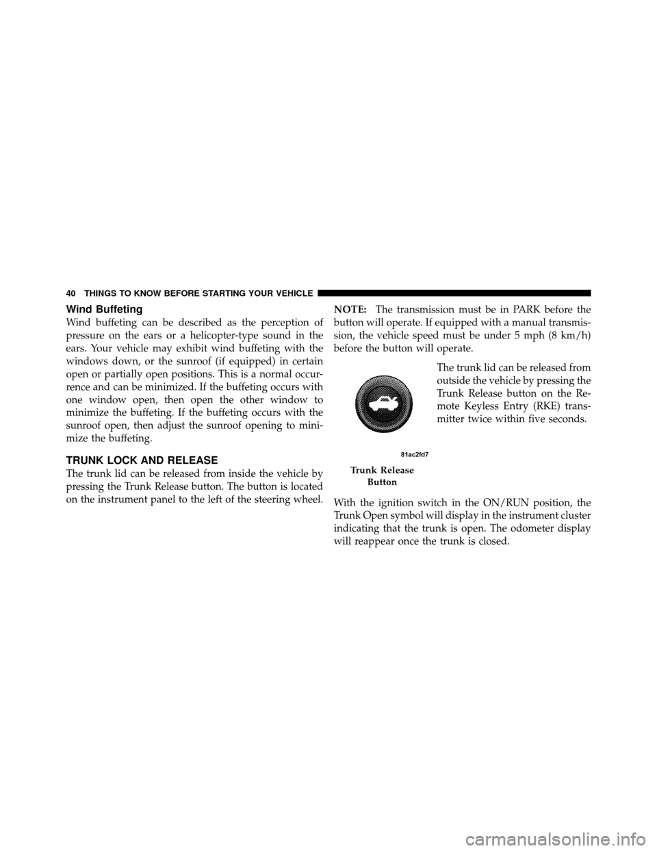
The trunk lid can be released from inside the vehicle by
pressing the Trunk Release button. The button is located
on the instrument panel to the left of the steering wheel.NOTE:
The transmission must be in PARK before the
button will operate. If equipped with a manual transmis-
sion, the vehicle speed must be under 5 mph (8 km/h)
before the button will operate.
The trunk lid can be released from
outside the vehicle by pressing the
Trunk Release button on the Re-
mote Keyless Entry (RKE) trans-
mitter twice within five seconds.
With the ignition switch in the ON/RUN position, the
Trunk Open symbol will display in the instrument cluster
indicating that the trunk is open. The odometer display
will reappear once the trunk is closed.Trunk Release Button
40 THINGS TO KNOW BEFORE STARTING YOUR VEHICLE
Page 147 of 490
Interior Lights
The interior lights come on when a door is opened.
To protect the battery, the interior lights will turn off
automatically 10 minutes after the ignition is placed in
the OFF position. This will occur if the interior lights
were switched on manually or are on because a door is
open. This includes the glove box light, but not the trunk
light. To restore interior light operation, either place the
ignition in the RUN position or cycle the light switch.
Dimmer Control
The dimmer control is located to the right of the head-
light switch. With the parking lights or headlights on,
rotating the dimmer control upward will increase the
brightness of the instrument panel lights and, if
equipped, the lighting in the door map pockets, door
handles and cupholders.
Dome Light Position
Rotate the dimmer control completely upward to the
second detent to turn on the interior lights. The interior
lights will remain on when the dimmer control is in this
position.
Interior Light Defeat (OFF)
Rotate the dimmer control to the extreme bottom off
position. The interior lights will remain off when the
doors are open.
Parade Mode (Daytime Brightness Feature)
Rotate the dimmer control upward to the first detent.
This feature brightens all text displays such as the
odometer, Electronic Vehicle Information Center (EVIC),
and radio when the parking lights or headlights are on.
3
UNDERSTANDING THE FEATURES OF YOUR VEHICLE 145
Page 178 of 490

INSTRUMENT CLUSTER DESCRIPTIONS
1. Fuel Gauge
The pointer shows the level of fuel in the fuel tank when
the ignition switch is placed in the ON/RUN position.
2. Trip Odometer Button
Press this button to change the display from odometer to
either of two trip odometer settings. The letter “A” or “B”
will appear when in the trip odometer mode. Push in and
hold the button for two seconds to reset the trip odometer
to 0 miles (km). The odometer must be in TRIP mode to
reset it.
3. Speedometer
Indicates vehicle speed.
4. Electronic Speed Control Indicator LightThis light will turn on when the electronic
speed control is on. 5. Tachometer
The red segments indicate the maximum permissible
engine revolutions per minute (RPM x 1000) for each gear
range. Ease up on the accelerator before reaching the red
area.
6. Charging System Warning Light
This light shows the status of the electrical charg-
ing system. The light should turn on when the
ignition switch is placed in the ON/RUN position and
remain on briefly as a bulb check. If the light stays on or
turns on while driving, turn off some of the vehicle’s
non-essential electrical devices (i.e., radio) or slightly
increase engine speed (if at idle). If the light remains on,
it means that the charging system is experiencing a
problem. See your local authorized dealer to obtain
service immediately.
If jump starting is required, refer to “Jump Starting
Procedures” in “What To Do In Emergencies”.
176 UNDERSTANDING YOUR INSTRUMENT PANEL
Page 183 of 490
17. Shift Lever Indicator — Automatic Transmission
Only
The Shift Lever Indicator is self-contained within the
instrument cluster. It displays the gear position of the
automatic transmission.
18. Front Fog Light Indicator — If EquippedThis indicator will illuminate when the front fog
lights are on.
19. Odometer / Electronic Vehicle Information Center
(EVIC) Display Area
The odometer display shows the total distance the ve-
hicle has been driven. The trip odometer shows indi-
vidual trip mileage. Refer to “Trip Odometer Button” for
additional information.
NOTE: U.S. Federal regulations require that upon trans-
fer of vehicle ownership, the seller certify to the pur-
chaser the correct mileage that the vehicle has been
driven. If your odometer needs to be repaired or serviced, the repair technician should leave the odometer reading
the same as it was before the repair or service. If s/he
cannot do so, then the odometer must be set at zero, and
a sticker must be placed in the door jamb stating what the
mileage was before the repair or service. It is a good idea
for you to make a record of the odometer reading before
the repair/service, so that you can be sure that it is
properly reset, or that the door jamb sticker is accurate if
the odometer must be reset at zero.
Vehicle Odometer Messages
When the appropriate conditions exist, the following
messages will display in the odometer:
ECO
...................... Fuel Saver Indicator
gASCAP ............ Loose Fuel Filler Cap Message
Lo tirE ...................... LowTirePr essure
noFUSE .......................... Fuse Fault
CHAngE OIL ............... Oil Change Required
4
UNDERSTANDING YOUR INSTRUMENT PANEL 181
Page 184 of 490
This display shows the Electronic Vehicle Information
Center (EVIC) messages when the appropriate conditions
exist. Refer to Electronic Vehicle Information Center
(EVIC) for further information.
ECO (Fuel Saver Indicator) — If Equipped
The ECO indicator will illuminate when you are driving
in a fuel efficient manner and can be used to modify
driving habits in order to increase fuel economy. The
ECO display will toggle on and off depending on driving
habits and vehicle usage.
gASCAP
If the vehicle diagnostic system determines that the fuel
filler cap is loose, improperly installed, or damaged, a
“gASCAP” message will display in the odometer display
area. Tighten the fuel filler cap properly and press the
TRIP ODOMETER button to turn off the message. If the
problem continues, the message will appear the next time
the vehicle is started.A loose, improperly installed, or damaged fuel filler cap
may also turn on the Malfunction Indicator Light (MIL).
Lo tirE
When the appropriate condition exists, the odometer
display will toggle between Lo and tirE for three cycles.
noFUSE
If the vehicle diagnostic system determines that the Igni-
tion Off Draw (IOD) fuse is improperly installed, or
damaged, a “noFUSE” message will display in the odom-
eter display area. For further information on fuses and fuse
locations refer to “Fuses” in “Maintaining Your Vehicle”.
CHAngE OIL (Base Cluster)
Your vehicle is equipped with an engine oil change
indicator system. The “CHAngE OIL” message will flash
in the instrument cluster odometer for approximately
12 seconds after a single chime has sounded to indicate
the next scheduled oil change interval. The engine oil
change indicator system is duty cycle based, which
182 UNDERSTANDING YOUR INSTRUMENT PANEL
Page 185 of 490
means the engine oil change interval may fluctuate
dependent upon your personal driving style.
Unless reset, this message will continue to display each
time you place the ignition switch in the ON/RUN
position. To turn off the message temporarily, press and
release the TRIP ODOMETER button on the instrument
cluster. To reset the oil change indicator system (after
performing the scheduled maintenance) perform the
following procedure:
1. Place the ignition switch in the ON/RUN position (do
not start the engine).
2. Fully depress the accelerator pedal, slowly, three times
within 10 seconds.
3. Turn the ignition switch to the OFF position.
NOTE:If the indicator message illuminates when you
start the engine, the oil change indicator system did not
reset. If necessary, repeat these steps. 20. Brake Warning Light
This light monitors various brake functions,
including brake fluid level and parking brake
application. If the brake light turns on it may
indicate that the parking brake is applied, that
the brake fluid level is low, or that there is a problem with
the anti-lock brake system reservoir.
If the light remains on when the parking brake has been
disengaged, and the fluid level is at the full mark on the
master cylinder reservoir, it indicates a possible brake
hydraulic system malfunction. In this case, the light will
remain on until the condition has been corrected.
The dual brake system provides a reserve braking capac-
ity in the event of a failure to a portion of the hydraulic
system. A leak in either half of the dual brake system is
indicated by the Brake Warning Light which will turn on
when the brake fluid level in the master cylinder has
dropped below a specified level.
4
UNDERSTANDING YOUR INSTRUMENT PANEL 183
Page 205 of 490
Keyless Enter-N-Go (Passive Entry)
This feature allows you to lock and unlock the vehicle’s
door(s) without having to press the RKE transmitter lock
or unlock buttons. To make your selection, press and
release the SELECT button until a check-mark appears
next to the feature showing the system has been activated
or the check-mark is removed showing the system has
been deactivated. Refer to “Keyless Enter-N-Go” in
“Things To Know Before Starting Your Vehicle”.
Display Units of Measure In
The EVIC, odometer, and Uconnect™ gps (if equipped)
can be changed between English and Metric units of
measure. To make your selection, press and release the
SELECT button until “ENGLISH” or “METRIC” appears.
MEDIA CENTER 730N/430/430N (RHR/RER/RBZ/
RHB) CD/DVD/HDD/NAV — IF EQUIPPED
NOTE:The sales code is located on the lower right side
of the unit’s faceplate.
Refer to your Uconnect™ Multimedia RHR, RER, RBZ or
RHB user’s manual for detailed operating instructions.
Operating Instructions
(Voice Command System) — If Equipped
Refer to “Voice Command” in the Uconnect™ User
Manual located on the DVD for further details.
Operating Instructions (Uconnect™ Phone) —
If Equipped
Refer to “Uconnect™ Phone” in the Uconnect™ User
Manual located on the DVD for further details.
4
UNDERSTANDING YOUR INSTRUMENT PANEL 203
Page 311 of 490

WARNING! (Continued)
•Failure to equip your vehicle with tires having
adequate speed capability can result in sudden tire
failure and loss of vehicle control.
CAUTION!
Replacing original tires with tires of a different size
may result in false speedometer and odometer read-
ings.
TIRE CHAINS
Use only compact chains or other traction aids that meet
SAE type “Class S” specifications. Chains must be the
proper size for the vehicle, as recommended by the chain
manufacturer. Only install tire chains on P235/55R18 size
tires.
NOTE:Do not use tire chains on a compact spare tire.
CAUTION!
To avoid damage to your vehicle or tires, observe the
following precautions:
•Because of restricted chain clearance between tires
and other suspension components, it is important
that only chains in good condition are used. Bro-
ken chains can cause serious damage. Stop the
vehicle immediately if noise occurs that could
indicate chain breakage. Remove the damaged
parts of the chain before further use.
•Install chains on the rear wheels as tightly as
possible and then retighten after driving about1�2
mile (0.8 km).
•Do not exceed 30 mph (48 km/h).
•Drive cautiously and avoid severe turns and large
bumps, especially with a loaded vehicle.
•Use on rear wheels only.
(Continued)
5
STARTING AND OPERATING 309