Page 155 of 486

Intermittent Wiper System
Use the intermittent wiper when weather conditions
make a single wiping cycle, with a variable pause be-
tween cycles, desirable. Select the delay interval by
turning the end of the lever. Rotate the end of the lever
upward (clockwise) to decrease the delay time and
downward (counterclockwise) to increase the delay time.
The delay can be regulated from a maximum of approxi-
mately 18 seconds between cycles, to a cycle every
second.
NOTE:The wiper delay times depend on vehicle speed.
If the vehicle is moving less than 10 mph (16 km/h),
delay times will be doubled.
Windshield Washers
To use the washer, pull the control lever toward you and
hold while spray is desired. If the lever is pulled while in
the delay range, the wiper will operate in low-speed
while the lever is pulled and for two wipe cycles after the
lever is released, and then resume the intermittent inter-
val previously selected.
If the lever is pulled while in the off position, the wipers
will operate for two wipe cycles, then turn off.
WARNING!
Sudden loss of visibility through the windshield
could lead to a collision. You might not see other
vehicles or other obstacles. To avoid sudden icing of
the windshield during freezing weather, warm the
windshield with the defroster before and during
windshield washer use.
3
UNDERSTANDING THE FEATURES OF YOUR VEHICLE 153
Page 157 of 486

Push down on the lever to unlock the column. With one
hand firmly on the steering wheel, move the steering
column up or down as desired. Push the lever up to lock
the column firmly in place.
WARNING!
Do not adjust the steering column while driving.
Adjusting the steering column while driving or driv-
ing with the steering column unlocked, could cause
the driver to lose control of the vehicle. Be sure the
steering column is locked before driving your ve-
hicle. Failure to follow this warning may result in
serious injury or death.
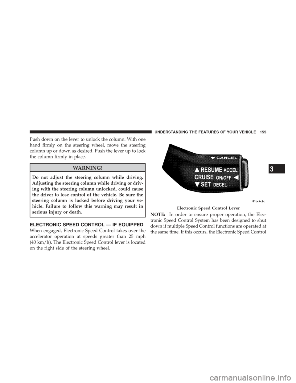
ELECTRONIC SPEED CONTROL — IF EQUIPPED
When engaged, Electronic Speed Control takes over the
accelerator operation at speeds greater than 25 mph
(40 km/h). The Electronic Speed Control lever is located
on the right side of the steering wheel.NOTE:
In order to ensure proper operation, the Elec-
tronic Speed Control System has been designed to shut
down if multiple Speed Control functions are operated at
the same time. If this occurs, the Electronic Speed Control
Electronic Speed Control Lever
3
UNDERSTANDING THE FEATURES OF YOUR VEHICLE 155
Page 165 of 486

If you unplugged the device for training, plug it back in
at this time.
Then proceed with Step 4 under “Programming
HomeLink�” earlier in this section.
Using HomeLink�
To operate, press and release the programmed
HomeLink�button. Activation will now occur for the
trained device (i.e., garage door opener, gate operator,
Security system, entry door lock, home/office lighting,
etc.,). The handheld transmitter of the device may also be
used at any time.
Reprogramming A Single HomeLink �Button
To reprogram a channel that has been previously trained,
follow these steps:
1. Turn the ignition switch to the ON/RUN position. 2. Press and hold the desired HomeLink�
button until
the indicator light begins to flash after 20 seconds. Do not
release the button.
3. Without releasing the button, proceed with Program-
ming HomeLink� Step 2 and follow all remaining steps.
Security
It is advised to erase all channels before you sell or turn
in your vehicle.
To do this, press and hold the two outside buttons for
20 seconds until the red indicator flashes. Note that all
channels will be erased. Individual channels cannot be
erased.
The HomeLink�Universal Transceiver is disabled when
the Vehicle Security Alarm is active.
3
UNDERSTANDING THE FEATURES OF YOUR VEHICLE 163
Page 170 of 486
Ignition Off Operation
For vehicles not equipped with the Electronic Vehicle
Information Center (EVIC), the power sunroof switch
will remain active for 45 seconds after the ignition switch
is turned to the LOCK position. Opening either front
door will cancel this feature.
For vehicles equipped with the EVIC, the power sunroof
switch will remain active for up to approximately ten
minutes after the ignition switch is turned to the LOCK
position. Opening either front door will cancel this
feature. The time is programmable. Refer to “Electronic
Vehicle Information Center (EVIC)/Personal Settings
(Customer-Programmable Features)” in “Understanding
Your Instrument Panel” for further information.
ELECTRICAL POWER OUTLETS
There is a standard 12 Volt (13 Amp) power outlet located
in the instrument panel for added convenience. This
power outlet can power cellular phones, electronics and
other low power devices.
12 Volt Power Outlet
168 UNDERSTANDING THE FEATURES OF YOUR VEHICLE
Page 196 of 486

Further overheating will cause the temperature gauge to
passH, the indicator will continuously flash and a
continuous chime will occur until the engine is allowed
to cool.
If the light turns on while driving, safely pull over and
stop the vehicle. If the A/C system is on, turn it off. Also,
shift the transmission into NEUTRAL and idle the ve-
hicle. If the temperature reading does not return to
normal, turn the engine off immediately and call for
service. Refer to “If Your Engine Overheats” in “What To
Do In Emergencies” for further information.
11. Brake Warning Light This light monitors various brake functions,
including brake fluid level and parking brake
application. If the brake light turns on it may
indicate that the parking brake is applied, that
the brake fluid level is low, or that there is a problem with
the anti-lock brake system reservoir. If the light remains on when the parking brake has been
disengaged, and the fluid level is at the full mark on the
master cylinder reservoir, it indicates a possible brake
hydraulic system malfunction or that a problem with the
Brake Booster has been detected by the Anti-Lock Brake
System (ABS) / Electronic Stability Control (ESC) system.
In this case, the light will remain on until the condition
has been corrected. If the problem is related to the brake
booster, the ABS pump will run when applying the brake
and a brake pedal pulsation may be felt during each stop.
The dual brake system provides a reserve braking capac-
ity in the event of a failure to a portion of the hydraulic
system. A leak in either half of the dual brake system is
indicated by the Brake Warning Light, which will turn on
when the brake fluid level in the master cylinder has
dropped below a specified level.
The light will remain on until the cause is corrected.
194 UNDERSTANDING YOUR INSTRUMENT PANEL
Page 197 of 486

NOTE:The light may flash momentarily during sharp
cornering maneuvers, which change fluid level condi-
tions. The vehicle should have service performed, and
the brake fluid level checked.
If brake failure is indicated, immediate repair is neces-
sary.
WARNING!
Driving a vehicle with the red brake light on is
dangerous. Part of the brake system may have failed.
It will take longer to stop the vehicle. You could have
a collision. Have the vehicle checked immediately.
Vehicles equipped with the Anti-Lock Brake System
(ABS), are also equipped with Electronic Brake Force
Distribution (EBD). In the event of an EBD failure, the
Brake Warning Light will turn on along with the ABS
Light. Immediate repair to the ABS system is required. Operation of the Brake Warning Light can be checked by
turning the ignition switch from the OFF position to the
ON/RUN position. The light should illuminate for ap-
proximately two seconds. The light should then turn off
unless the parking brake is applied or a brake fault is
detected. If the light does not illuminate, have the light
inspected by an authorized dealer.
The light also will turn on when the parking brake is
applied with the ignition switch in the ON/RUN posi-
tion.
NOTE:
This light shows only that the parking brake is
applied. It does not show the degree of brake application.
12. Tachometer
The white area of the scale shows the permissible engine
revolutions-per-minute (RPM x 1000) for each gear range.
Before reaching the red area, ease up on the accelerator to
prevent engine damage.
4
UNDERSTANDING YOUR INSTRUMENT PANEL 195
Page 200 of 486

five seconds after a single chime has sounded to indicate
the next scheduled oil change interval. The engine oil
change indicator system is duty cycle based, which
means the engine oil change interval may fluctuate
dependent upon your personal driving style.
Unless reset, this message will continue to display each
time you turn the ignition switch to the ON/RUN
position. To turn off the message temporarily, press and
release the Trip Odometer button on the instrument
cluster. To reset the oil change indicator system (after
performing the scheduled maintenance), refer to the
following procedure:1. Turn the ignition switch to the ON/RUN position.
Do not start the engine.
2. Fully depress the accelerator pedal slowly three
times within 10 seconds.
3. Turn the ignition switch to the OFF/LOCK position. NOTE:
If the indicator message illuminates when you
start the vehicle, the oil change indicator system did not
reset. If necessary, repeat this procedure.
15. Cruise Indicator — If Equipped This indicator shows that the Speed Control
system is ON.
16. Trip/Odometer Display Reset Button
Press this button to change the display from odometer to
either of the two trip odometer settings. Trip A or Trip B
will appear when in the trip odometer mode. Push in and
hold the button for two seconds to reset the trip odometer
to 0 miles (0 km). The odometer must be in Trip mode to
reset.
17. Electronic Throttle Control (ETC) Light This light informs you of a problem with the
Electronic Throttle Control (ETC) system. If a
problem is detected, the light will come on
while the engine is running. Cycle the ignition
198 UNDERSTANDING YOUR INSTRUMENT PANEL
Page 205 of 486

CAUTION!
Prolonged driving with the MIL on could cause
damage to the engine control system. It also could
affect fuel economy and drivability. If the MIL is
flashing, severe catalytic converter damage and
power loss will soon occur. Immediate service is
required.
WARNING!
A malfunctioning catalytic converter, as referenced
above, can reach higher temperatures than in normal
operating conditions. This can cause a fire if you
drive slowly or park over flammable substances such
as dry plants, wood, cardboard, etc. This could result
in death or serious injury to the driver, occupants or
others.26. Anti-Lock Brake (ABS) Light
This light monitors the Anti-Lock Brake System
(ABS). The light will turn on when the ignition
switch is turned to the ON/RUN position and
may stay on for as long as four seconds.
If the ABS light remains on or turns on while driving, it
indicates that the Anti-Lock portion of the brake system
is not functioning and that service is required. However,
the conventional brake system will continue to operate
normally if the BRAKE warning light is not on.
If the ABS light is on, the brake system should be serviced
as soon as possible to restore the benefits of Anti-Lock
brakes. If the ABS light does not turn on when the
ignition switch is turned to the ON/RUN position, have
the light inspected by an authorized dealer.
4
UNDERSTANDING YOUR INSTRUMENT PANEL 203